
Turning the Commodore 64 off and on every time it needs to be reset, may eventually cause the power switch to malfunction or even put unnecessary stress on the fragile chips. Because of this, people have been installing reset switches for years using a momentary contact that grounds the input of specific chips (e.g. the board side of resistor R50 in older versions of the Commodore 64 and the anode side of diode CR5 on the short boards). This little trick will do a so-called Warm Reset which clears any BASIC program stored in memory and resets the computer back to the opening blue screen. However, if a machine language program is running from disk, a simple Warm Reset will cause the screen to freeze, lock up the computer and the program will not be removed from memory. To circumvent this problem, a Cold Reset is needed which clears the machine language program and resets the computer back to the opening blue screen. Thus, a Cold Reset works almost like flipping the power switch off and on.
The Hardware Solution by Ray Carlsen
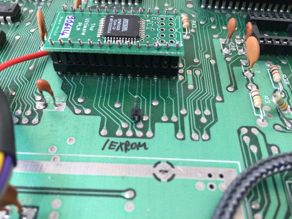
To do a Cold Reset, Ray Carlsen (of CARLSEN ELECTRONICS… a leader in trailing-edge technology) (link) discovered that if the /EXROM line of the PLA chip is held LOW (0V) for a little longer at reset time, the machine language program screen will clear and the computer will return to the blue start screen. The machine code program will still be in memory, but it can be overwritten with new data. Ray has implemented a Cold Reset switch using a hardware based solution using a resistor, a diode, a capacitor and a transistor. The circuit is then connected to the /EXROM line and controlled by an external switch drilled into the case.
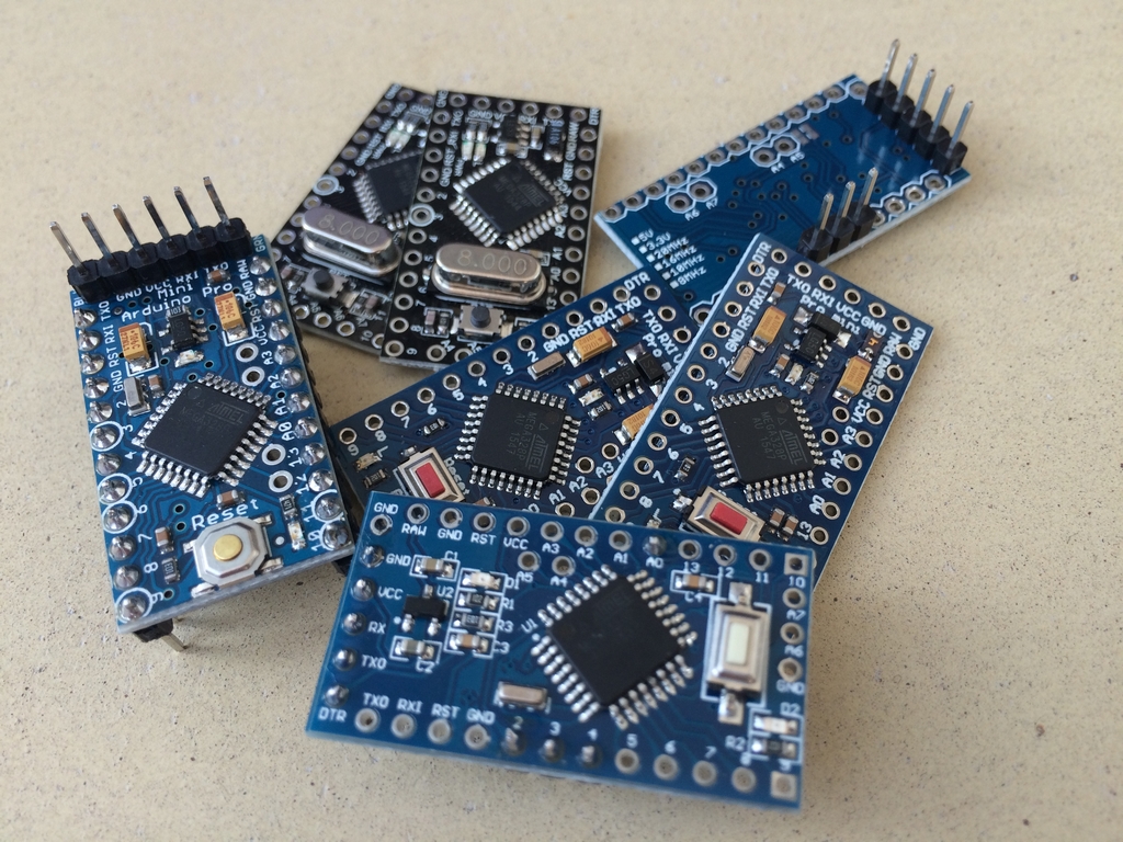
Ray’s reset circuit is a very nice solution, but I was thinking that maybe it could be over-engineered a little… like with an ATmega 328 processor running at 16MHz! Well, lo and behold, this is exactly what can be achieved with an Arduino Pro Mini.
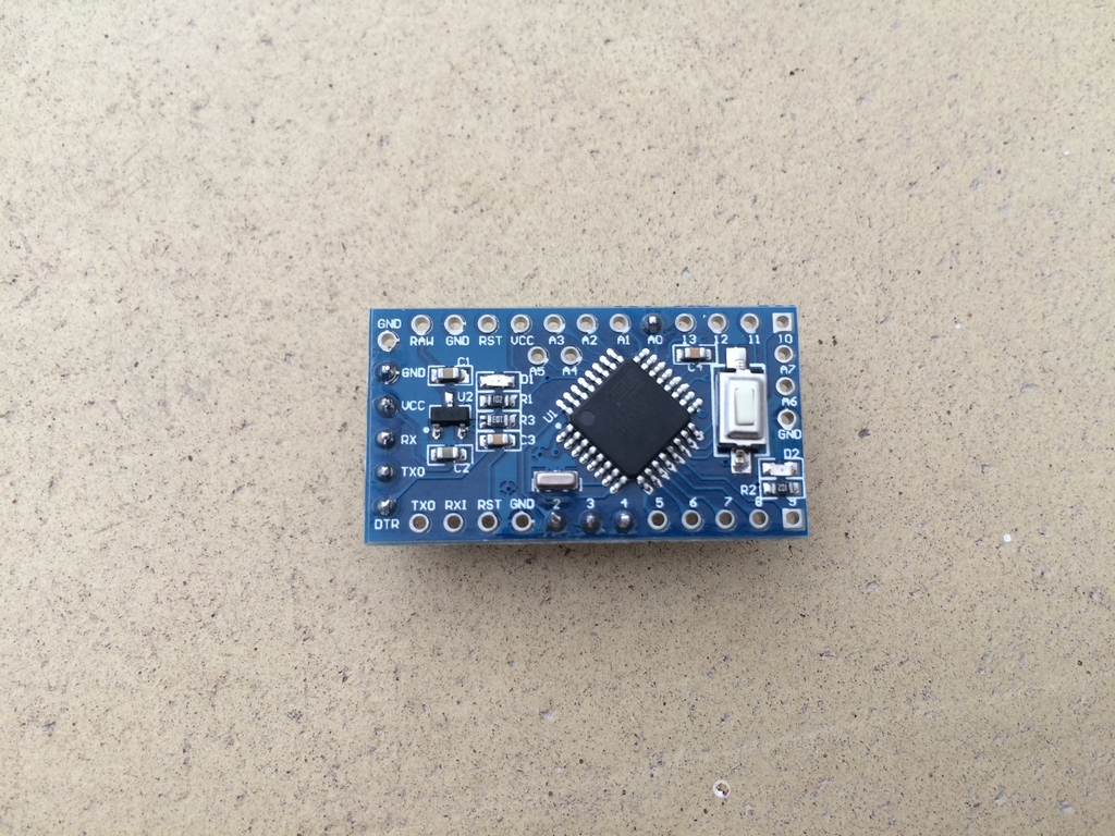
The device costs around 2-3 US$ (including shipping from China!) and has a size of only 33 x 18 mm. It has numerous digital and analog connections which can be programmed as inputs or outputs. In other words, it is perfect for making a Switchless Warm or Cold Reset solution for the Commodore 64.
Using the device for doing a Warm Reset is not new and has been described by vimfuego on Lemon64 (link) who also used it as a KERNAL selector. However, using it to do either a Warm or a Cold Reset, depending on the duration of a RESTORE key press, is not something I have seen before. So I had to make one for my ZIF modded C64C short board (link)!
Functionality of the Switchless Reset Switch
The reset function should be activated by pressing the RESTORE switch, hereby making it switchless as no holes need to be drilled into the case of the machine! If the RESTORE button is held for 2-4 seconds, the machine will do a Warm Reset. If the RESTORE button is held for 4-10 seconds, it will do a Cold Reset. If the button is held for less than 2 seconds or longer than 10 seconds, nothing will happen.
Implementation
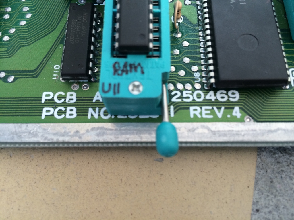
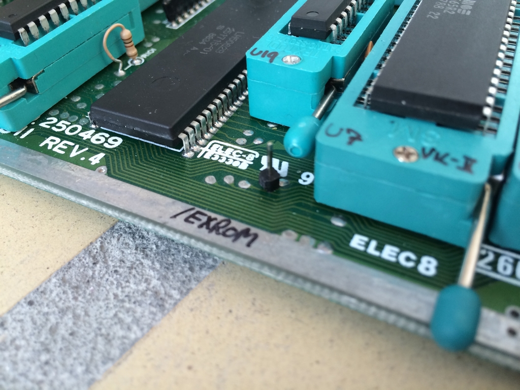
The Switchless Warm/Cold Reset device was first implemented in a Commodore 64C (Assy 250469 Rev. 4).
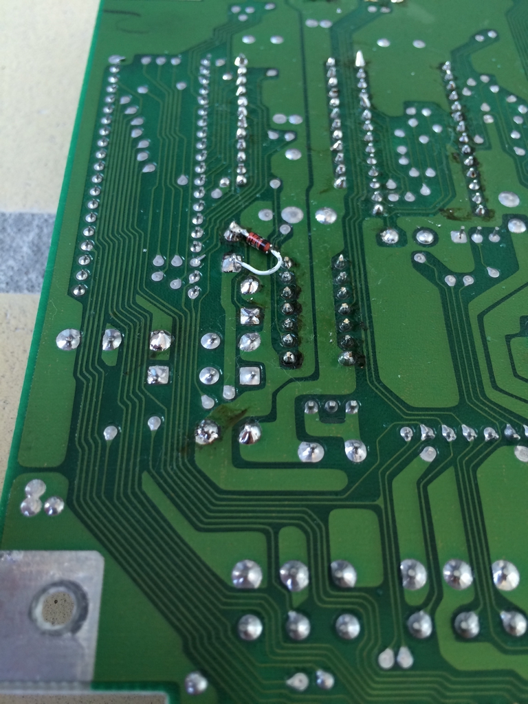
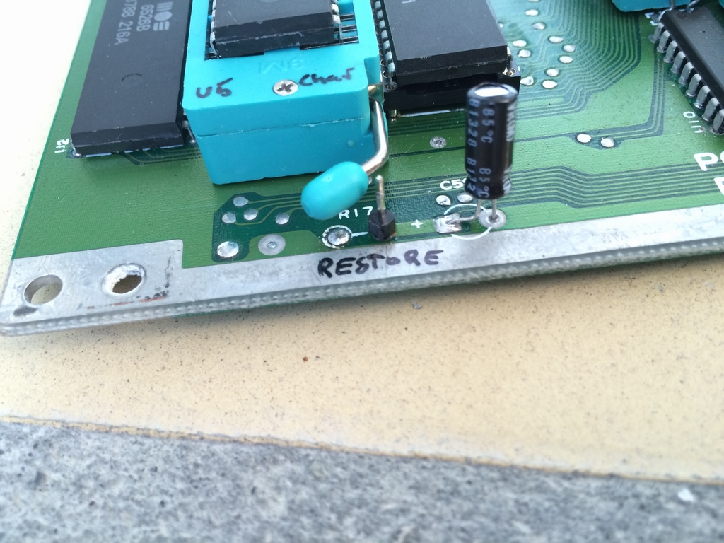
The location of the RESET line is a bit different on the newer short boards compared to the older breadbox versions. So care must be taken if a similar solution is implemented on one of these boards (now you’ve officially been warned!). In the C64C, a small pin was soldered to the anode of diode CR5 (RESET line). In order to do that, the diode had to be removed to the back side of the board.
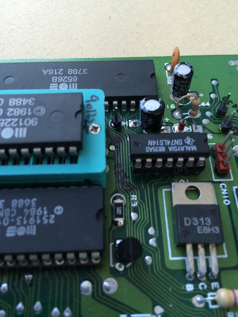
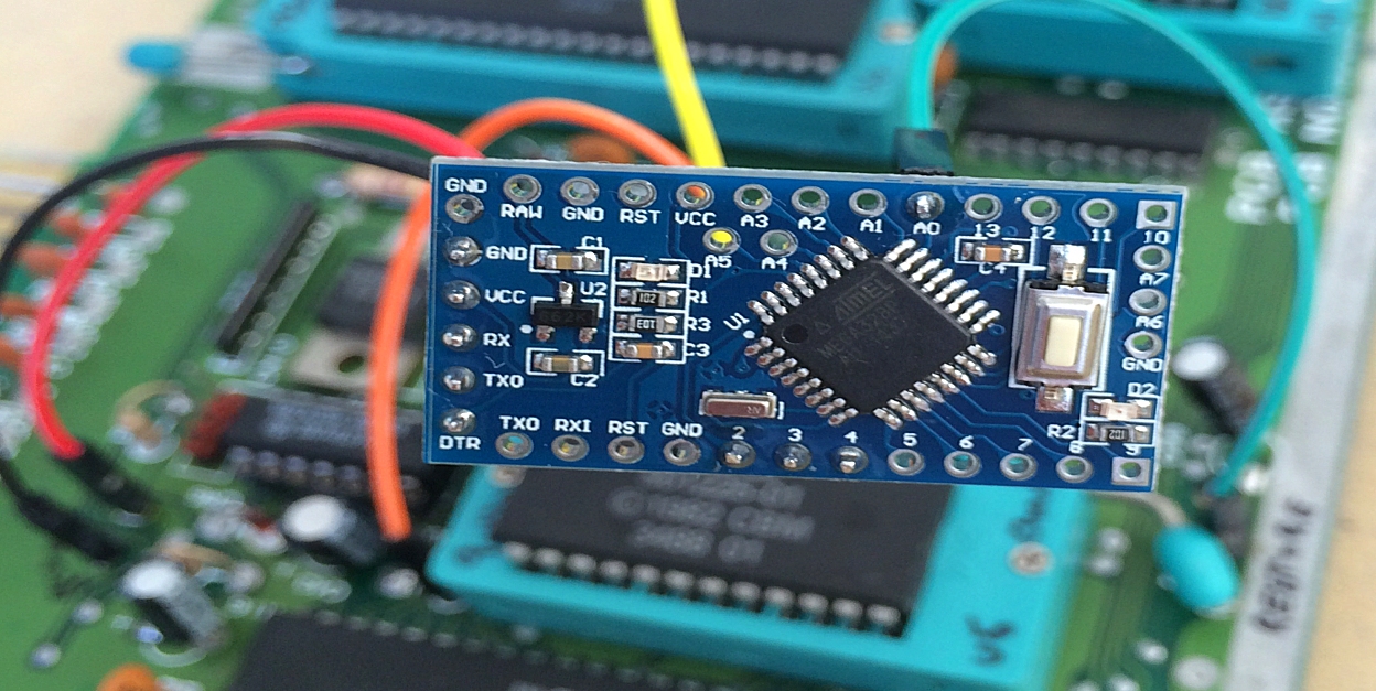
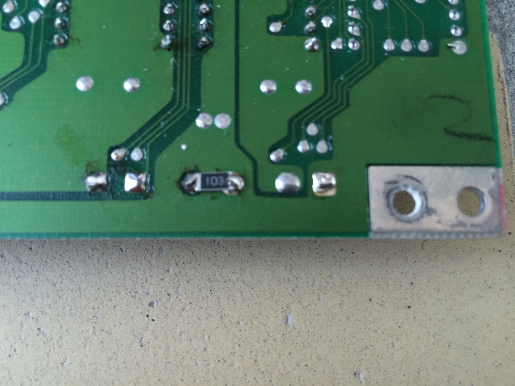
A second pin was soldered to the /EXROM line from the PLA which is the largest chip on the board. Two pins were soldered to Ground and 5V and used for powering the Arduino. Finally, a pin was soldered to the RESTORE signal coming from the keyboard. It’s the only button that has its own direct connection as the rest of the keyboard is configured as a matrix. In order to make the pin fit, a small SMD resistor was placed on the back side of the board as a replacement for resistor R17.
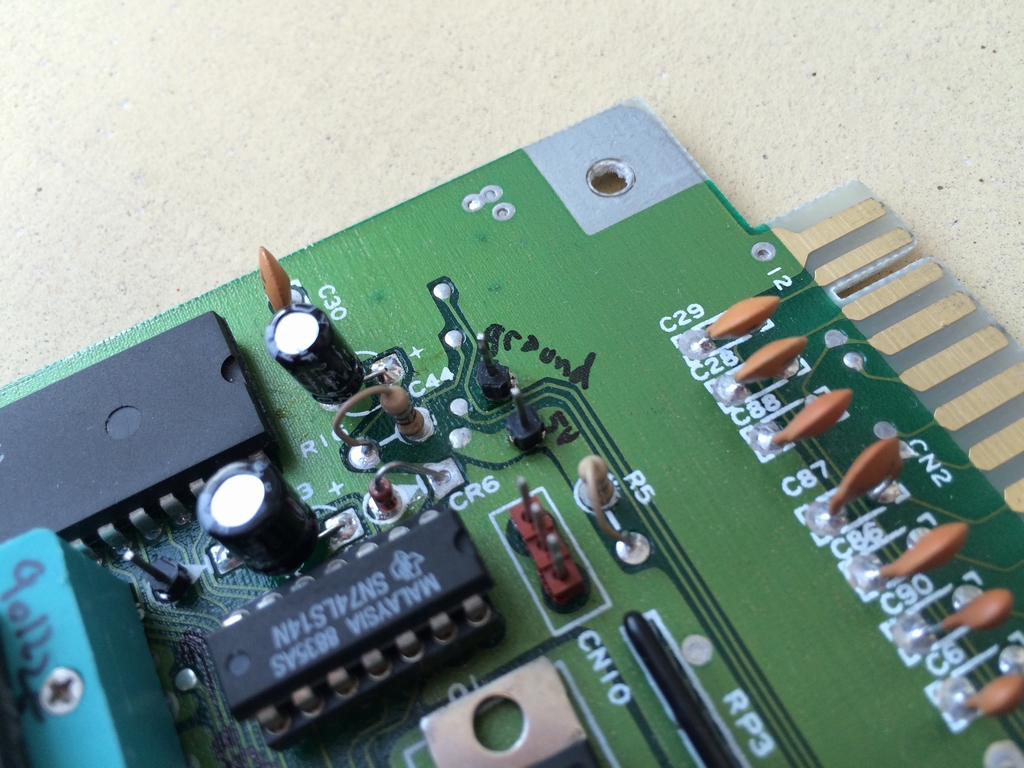
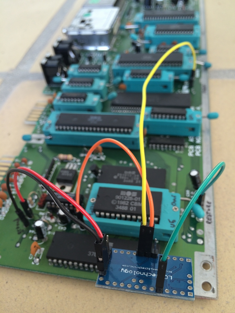
All five connections were then wired to pins on the Arduino. The RESET (orange) and /EXROM (yellow) wires were connected to two digital pins (Pin 3 and 4), the Ground (black) wire was connected to ground and the 5V (red) wire went to the Vcc pin. Finally, the RESTORE (green) wire was connected to an analog pin (Pin A0).
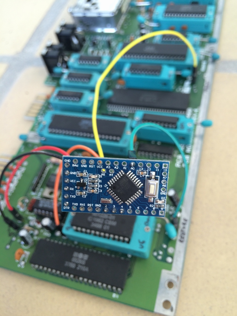
The RESTORE line usually has an ‘idle’ voltage of approximately 5V (HIGH) and drops to a few millivolts (LOW) when the key is held down. Thus, all the Arduino should do is monitor when the RESTORE line goes from HIGH to LOW, measure the time it is held low (due to a key press) and stop the timing when it goes HIGH again (the key has been released). The duration of the key press will then initiate either a Warm Reset, a Cold Reset or do nothing.
Well, no one said it should be that easy, right? For some unknown reason, the C64C motherboard I was using yielded some strange voltage measurements on the RESTORE line (which I discovered way way later…). I kept getting 1.2V without the switch being pressed which would be a LOW if a digital input was used on the Arduino Pro mini board. I therefore had to use an analog input (Pin A0) to accommodate the lower idle RESTORE line voltage on the C64C motherboard. The analog input of the Arduino simply converts the input voltage to an integer value between 0 and 1023. As long as the RESTORE line idle voltage is above approximately 0.5V, the functionality of the device is the same and only a few more lines of code were added to handle the analog input.
The Arduino code is pretty much straight forward. A small debounce function was included to filter the initial transitions/noise of the analog reading when the RESTORE key is being pressed. If the device is doing a Warm Reset, the RESET line of the motherboard is kept LOW for 200ms before going back to HIGH. If a Cold Reset is being performed, the RESET and /EXROM lines are both pulled LOW simultaneously. Both lines are then kept LOW for 200ms before the RESET line is set back to HIGH. To wipe the machine language program screen the /EXROM line is kept LOW for another 300ms before going back to HIGH and the computer resets just like Ray Carlsen promised! Easy peasy!
The code for the Arduino Pro Mini based Switchless Warm/Cold Reset solution for the Commodore 64 can be found here (link). Feel free to use the code for making your own switchless reset device and remember to use at your own risk!
Testing it
I did Warm and Cold Resets of a bunch of games. It turned out that especially three games (Commando, Creatures 2 and Montezuma’s Revenge) could not be reset using Warm Resets. Commando would just give me a black screen while the music would keep playing. Creatures 2 would fill the screen with rubbish characters and Montezuma’s Revenge would simply reload and nothing else would happen. Doing Cold Resets, all three games were cleared and the machine returned to the blue startup screen. Complete success!!
This is a small video of the reset switch in action:
Known Issues
During testing, no issues arose while using JiffyDOS, Commodore 1541 Diskette drives or SD2IEC devices. However, after implementing the Switchless Warm/Cold Reset Mod, a few issues did surface. Game carts (EasyFlash games and some game carts) would not load. Using a 1541 Ultimate II would exhibit strange behavior with the Arduino installed. However, this particular cartridge has its own reset switch so there is no real need for an extra reset option.
Programming the Arduino Pro Mini
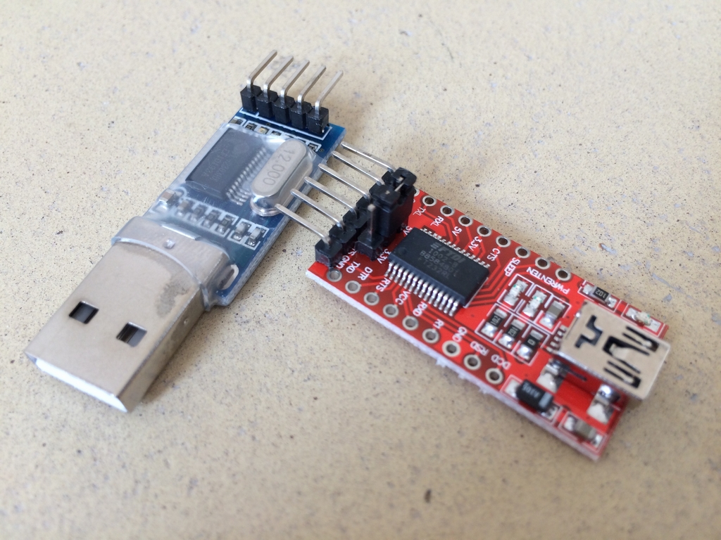
The Arduino programming software can be found here (link). Programming the Arduino Pro Mini can be done using a FTDI cable (USB to TTL Serial Adapter like the PL2303HX or FT232RL as shown below). Some of the Arduino Pro Mini’s come without a bootloader installed. Especially the ones from China may come without it. When trying to upload code to one of these, the Arduino gives you an error. This can be circumvented by pressing and holding the little reset switch on the Arduino while pressing the upload sketch button in the programming software. Whenever, the code is compiled (after a few seconds), the programming software starts uploading and the reset button must be released. The code takes a few more seconds to upload and that is it!
Making your Own
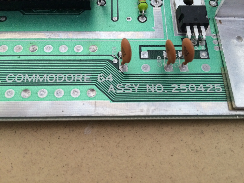
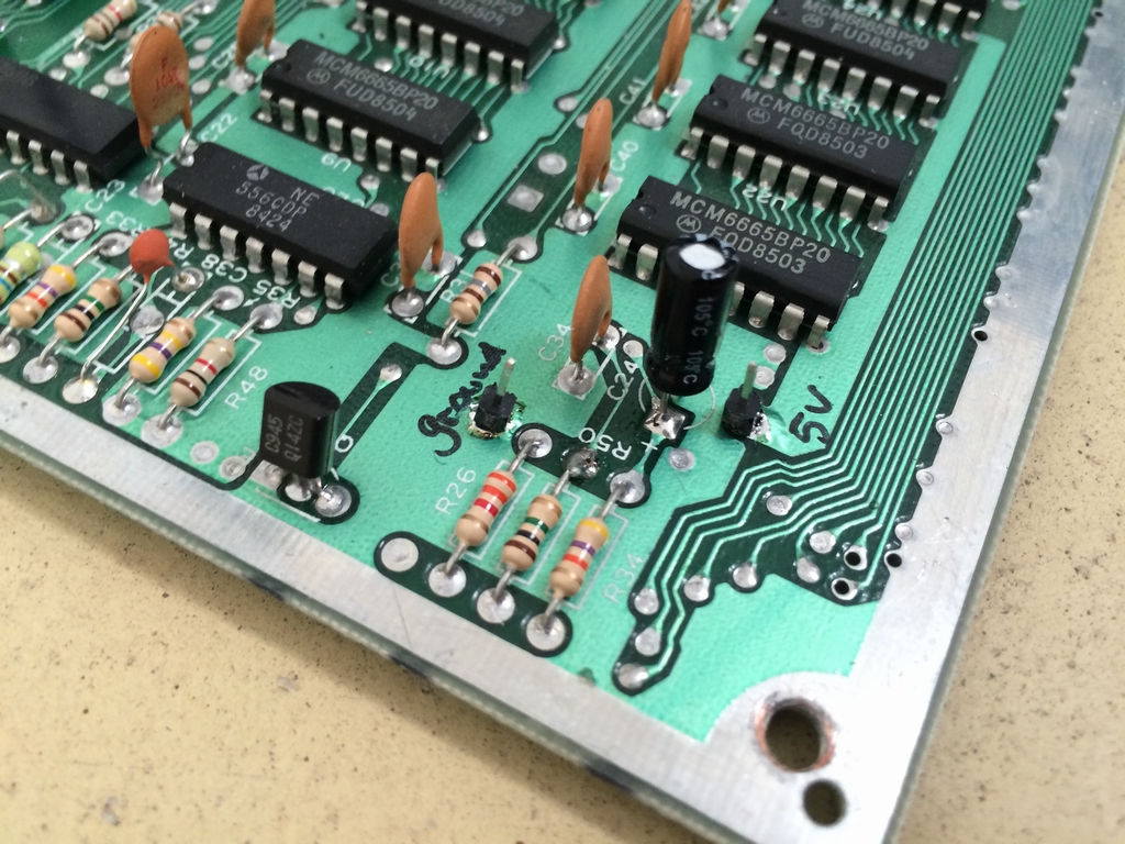
The reset solution is based on a 16MHz 5V Arduino Pro Mini and was tested on two Assy 250469 and two 250425 motherboards. The source code can be here (link). It should also work on all other C64 versions as long as the wires are connected to the correct spots (RESTORE, RESET, /EXROM, Ground & 5V) which differs among board versions. In this context, Ray Carlsen uses the RESET line of the inside leg of resistor R50 on all long boards (250407, 250425 & 250466). However, using that RESET line on 250425 boards (and presumably all other long boards) with the Arduino reset switch, only Warm Resets will be possible! To also enable Cold Resets, I discovered that the RESET line of the User Port (pin 3) must be used (which took me quite a while to figure out by the way!…).
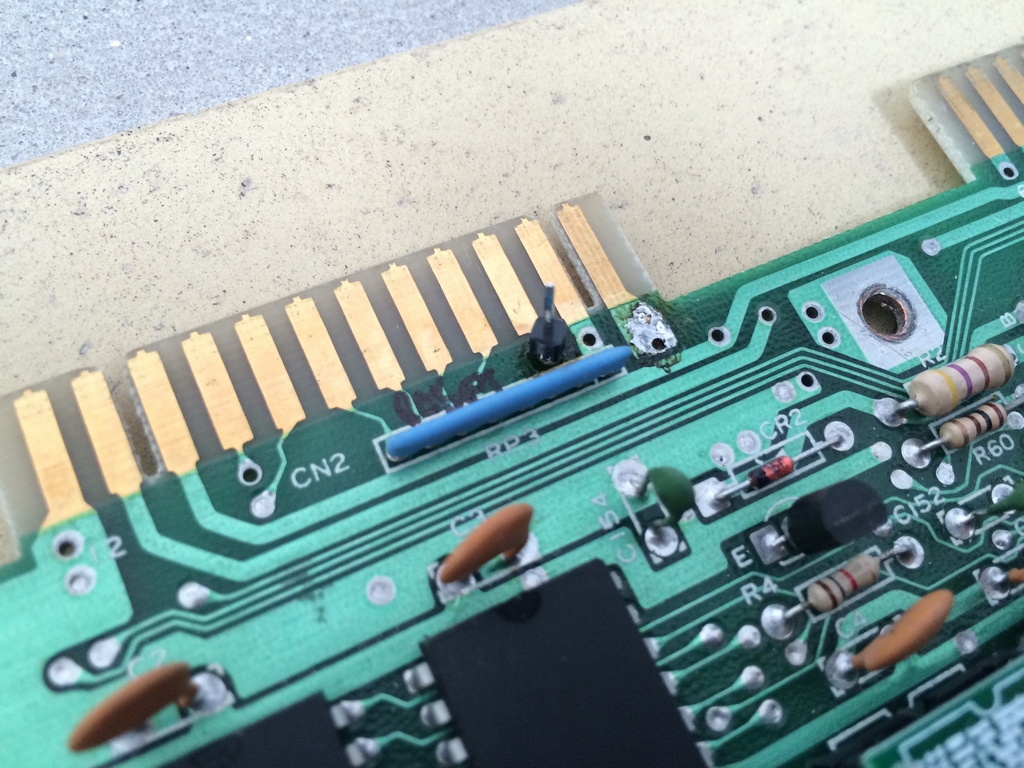
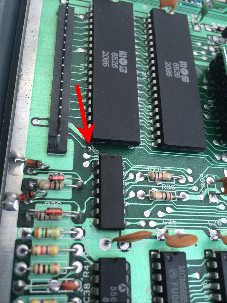
RESTORE line indicated by the red arrow.
Resetting an old 326298 board is a little more complicated and I really don’t recommend fiddling with these rare boards.
The source code for the Arduino Pro mini based Switchless Reset Mod can be found on the next page…
Regarding the 1.2V read on the RESTORE line. The RESTORE line is pulled up by 1 mega ohm, so you have to make sure that the arduina/atmega’s input impedance is high enough to not cause a voltage division there. I think you solved it, but if you can’t, then amplify it with a bc547 or a 2n7000 (nmos).
In the code I can’t see that the pinmode for reset is put back into INPUT mode. In other words, the arduino is constantly driving the reset line. The C64 is the one who pulls up the reset to 5V via a 1k resistor. After your code has pulled down the reset, put the pinmode back into input mode such that other devices who issue ressets (like cartridges etc) don’t send large currents from its driver into the driver inside the arduino.
Other than that, fascinating project !!
Hi there and thanks for the comments! The 1.2V on the RESTORE line is still a mystery. I’ve only seen it on that particular board and not on any other of my machines. Changing the input pin to analog was the simplest fix I could come up with 🙂
You are absolutely right about the pinmode of the Reset pin! I was not aware of this – my bad 🙁 I’ve updated the code so the pinmode is set as INPUT by default. Whenever the Arduino is requested to pull the Reset line to LOW (for Warm or Cold resets), the pinmode is changed to OUTPUT. After the reset, the pinmode is set back to INPUT again. Good point!
I like the analog input solution. It works reliably in my machines. As for the cartridge compatibility, I had some issues with the code when used with Final Cartridge III. Solved it by putting the /EXROM line in input mode during normal operations and flipping it to output mode just before resetting the same way as the RESET line is handled. Now it works like a charm with every cartridge I tested it against. Also I’ve put in a rom selector in my version as well. Thx for a nice and useful article.
Hi Gohanks. Thanks for your comment! I never tested the Switchless Reset Switch with a cartridge inserted. I’ve updated the code according to your directions so it should work with carts as well – thanks! Sounds very nice that you’ve also added a ROM selector option using the Arduino 🙂
Hey, I’ve added this mod to my C64C 250469 rev. B but only warm reset is working. Cold reset does nothing else than warm one do (the screen doesn’t go black, only results similar to SYS 64738). I’ve double checked connections with multimeter, between pin 46 of U8 (PLA’s /EXROM) and pin 4 of Arduino. My C64 had capacitors replaced, can it be the cause ? I’m not using any cart.
Hi r1me, I don’t think the capacitors have anything to with your machine doesn’t do cold resets. I sounds more like the /EXROM line is not being pulled LOW for some reason as the warm reset works (RESET line goes LOW). I used this soldering point (link) on an Assy 250469 short board for the /EXROM line. Is this point connected to pin 4 on your Arduino?