
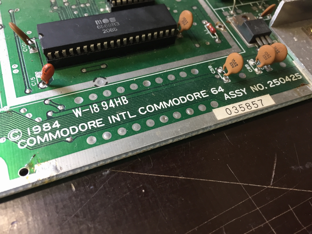
This machine is an Assy No. 250425 long board. At startup it had a black screen.
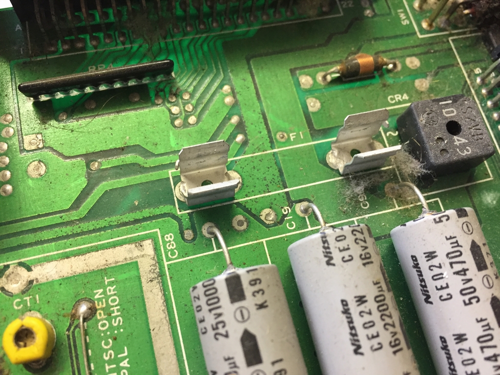
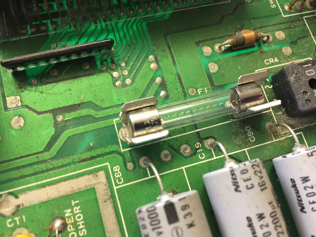
First I did a visual inspection of the board and immediately spotted the missing fuse. Adding a fuse did not fix the black screen.
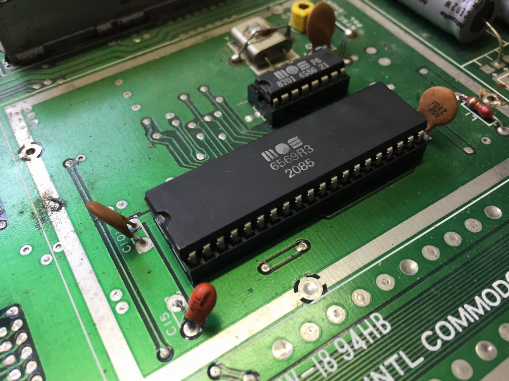
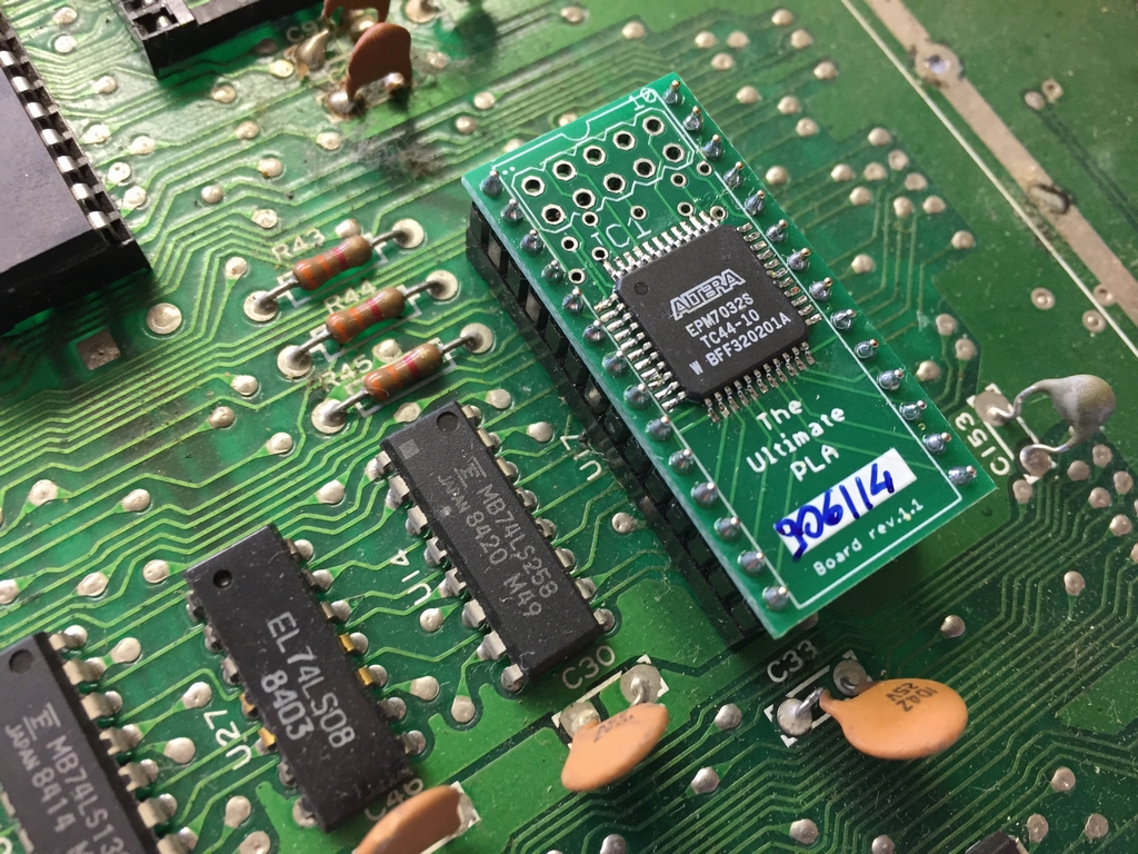
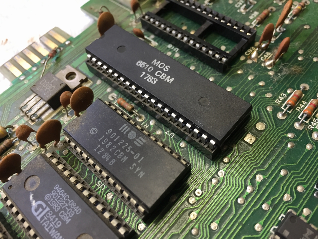
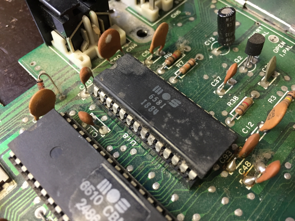
On this particular board, a lot of the large chips are socketed and I therefor replaced them with known working ones. This included the VIC-II, the PLA, the CIA’s and the MPU. I also removed the SID as this is not needed for faultfinding of a black screen.
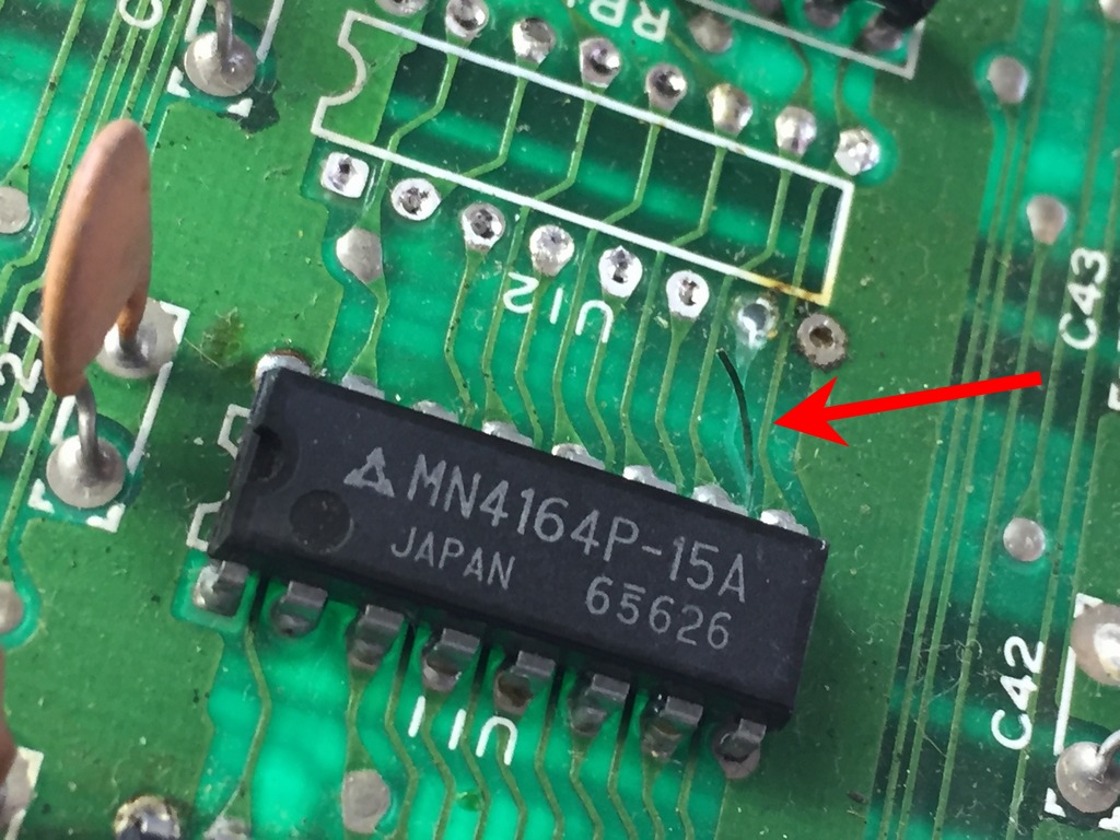
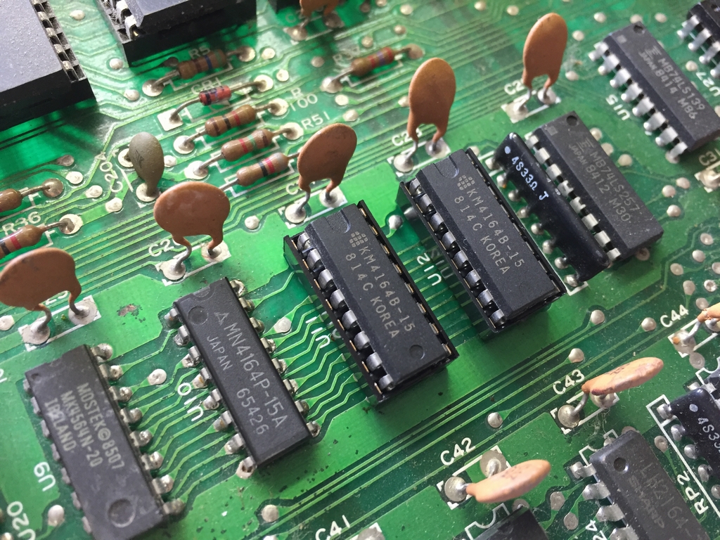
The black screen persisted. I then ran my Dead Test Cartridge which indicated a fault in the RAM chip at U12.
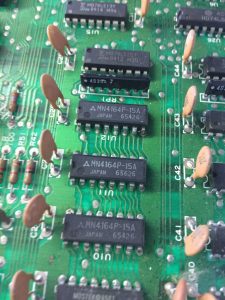
Unfortunately, a trace was released from the board when removing U12. The memory chip at U11 was therefore also removed. Red arrows show the broken trace.
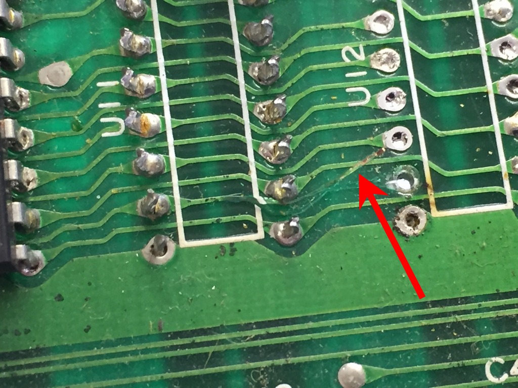
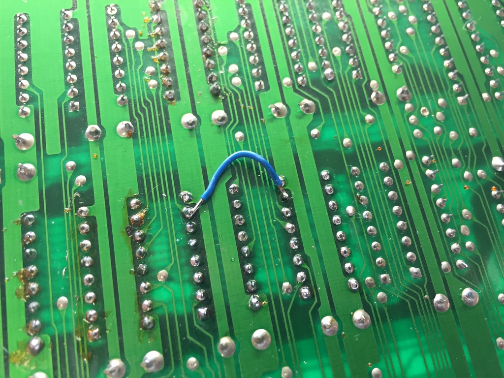
Two sockets were inserted and the broken trace was repaired using a piece of blue wire on the backside of the board.
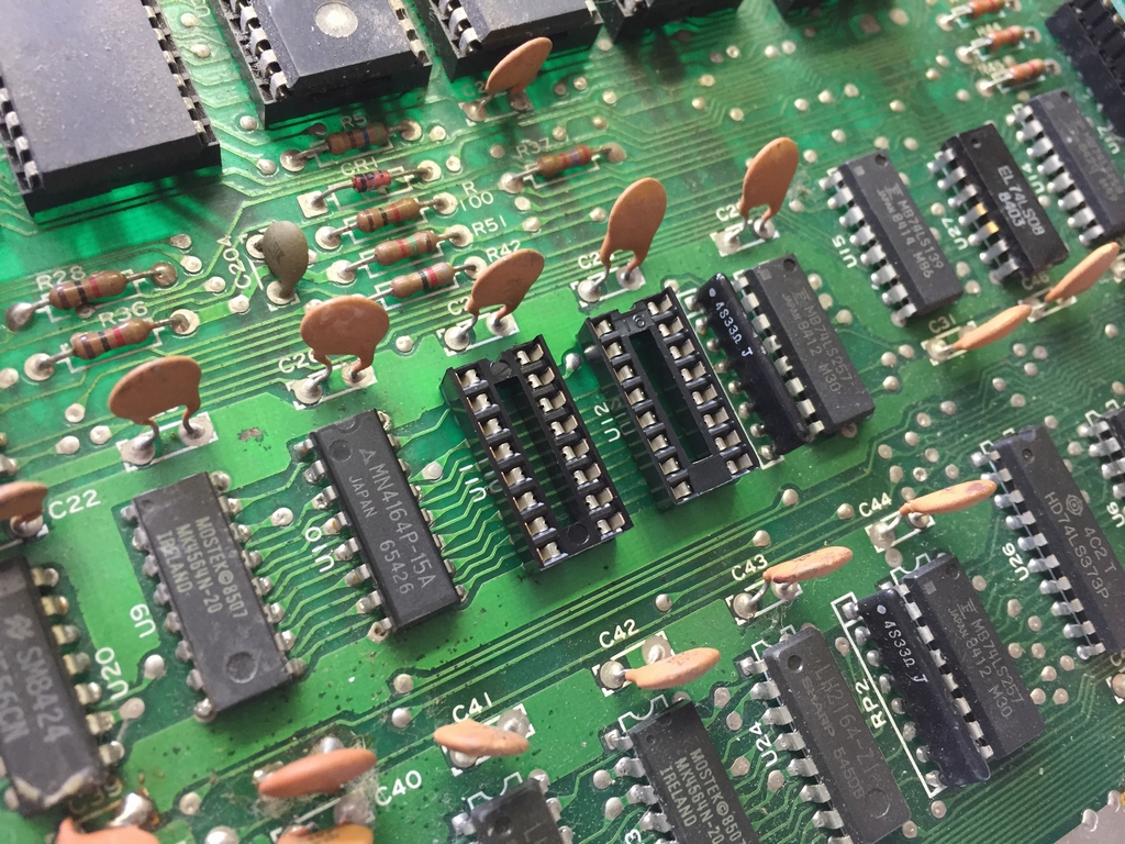
…and two fresh new RAM chips were inserted.
Nevertheless, the Dead Test Cart kept givning me a memory fault. After powering up the machine, the RAM chip at U9 would get really hot, so I also replaced this chip.
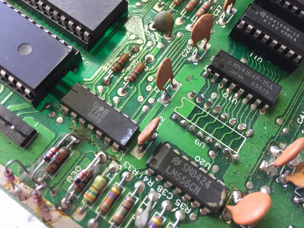
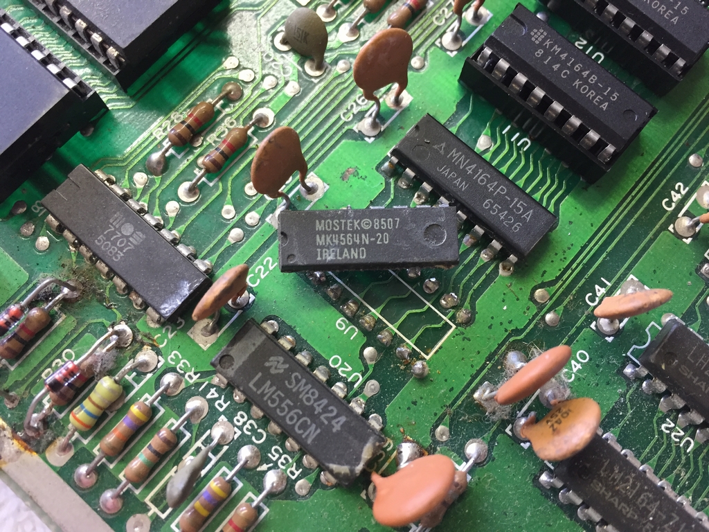
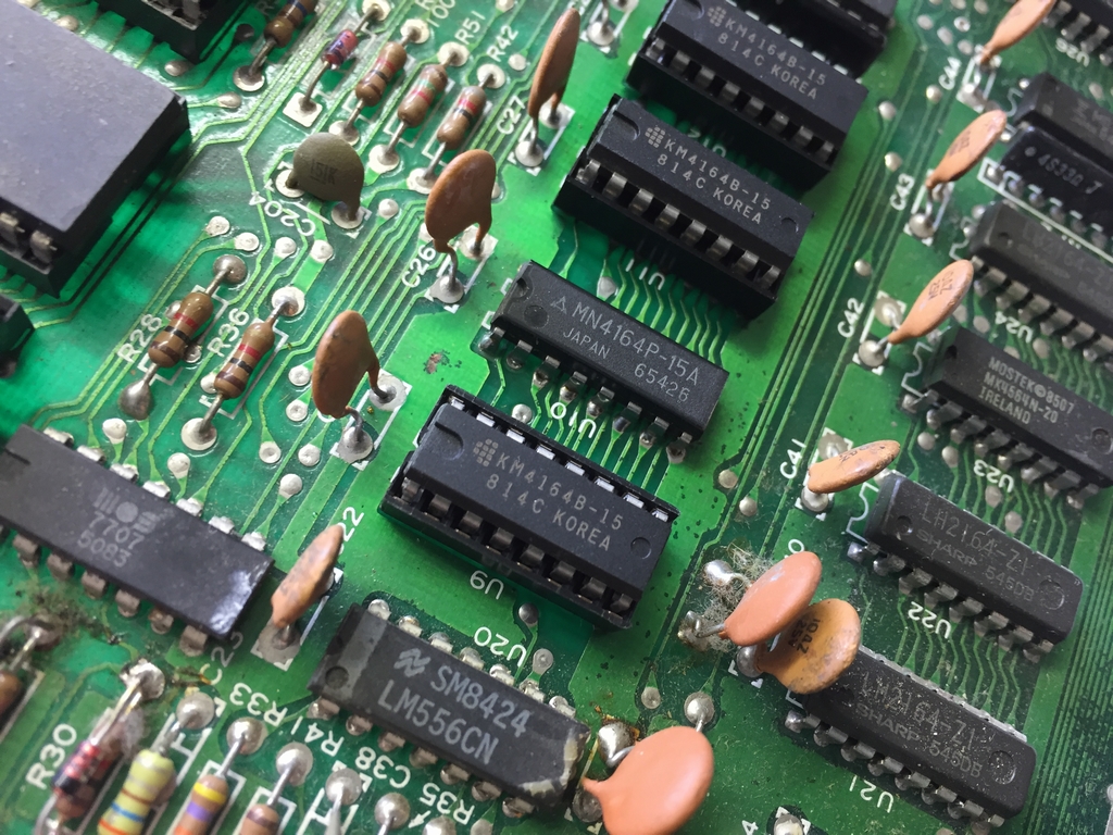
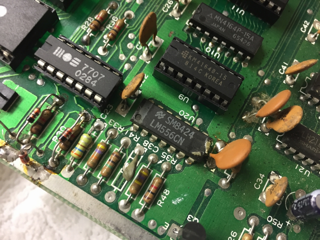
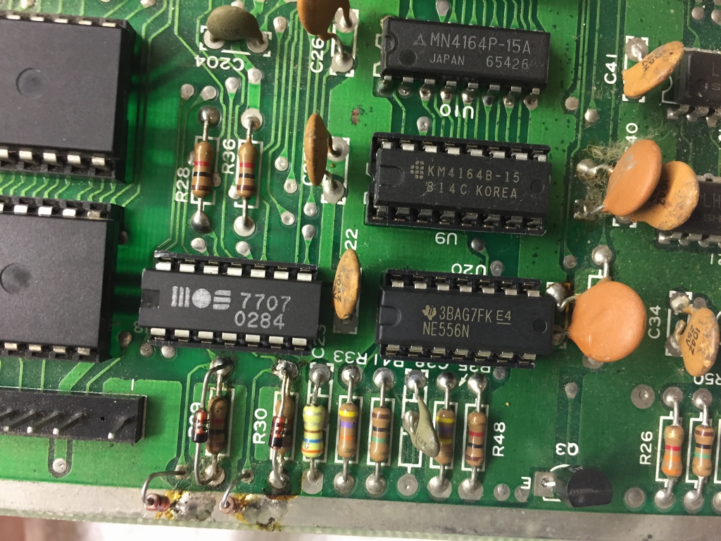
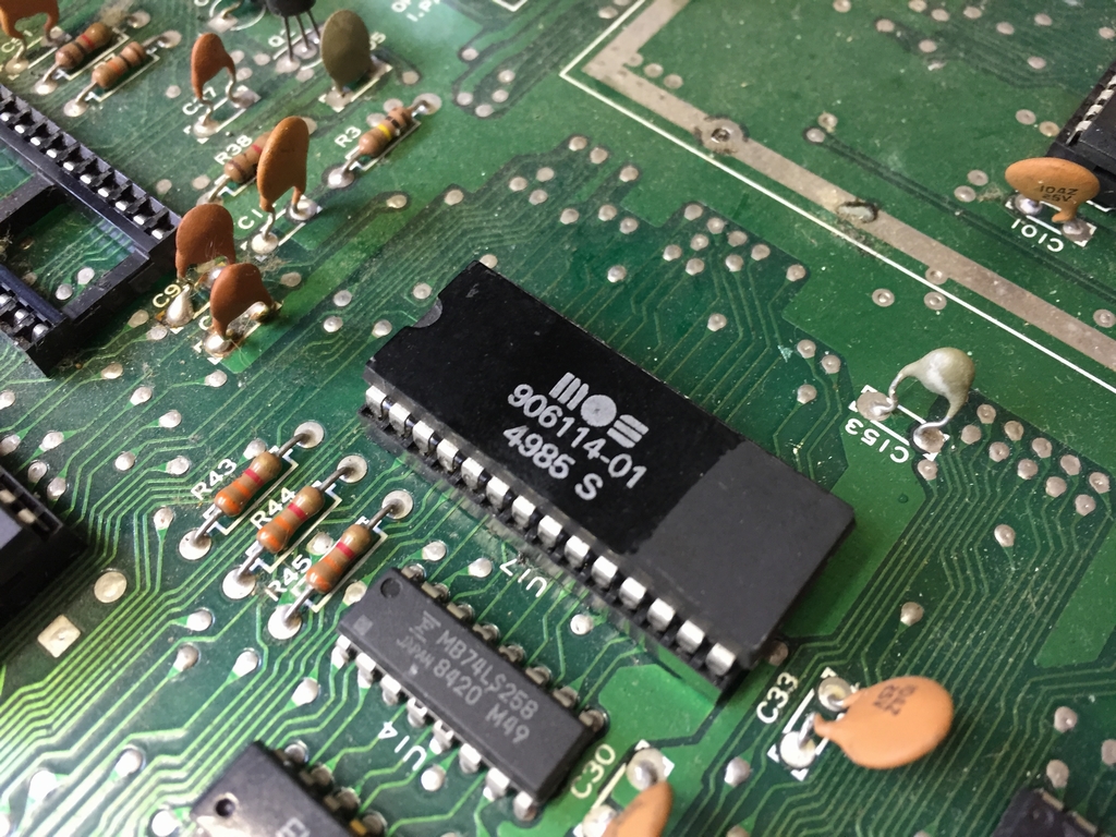
This removed the memory fault indications by the Dead Test Cart, but the black screen remained. I left the board powered on and started touching all the chips and noticed that the 7406 logic chip at U8 also got very warm. According to Ray Carlsen (link), the 7406 logic chip at U8 may also cause a blank screen. I therefore replaced the chip at U8 – this chip is called a MOS 7707 on this particular board and is known to have a high failure rate.

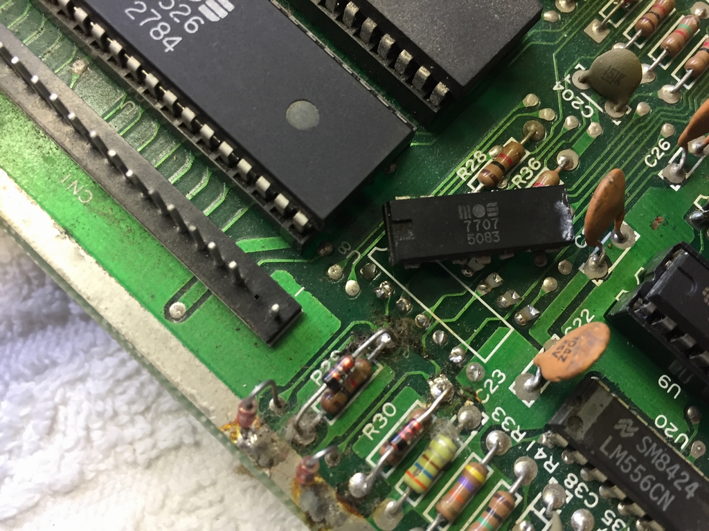
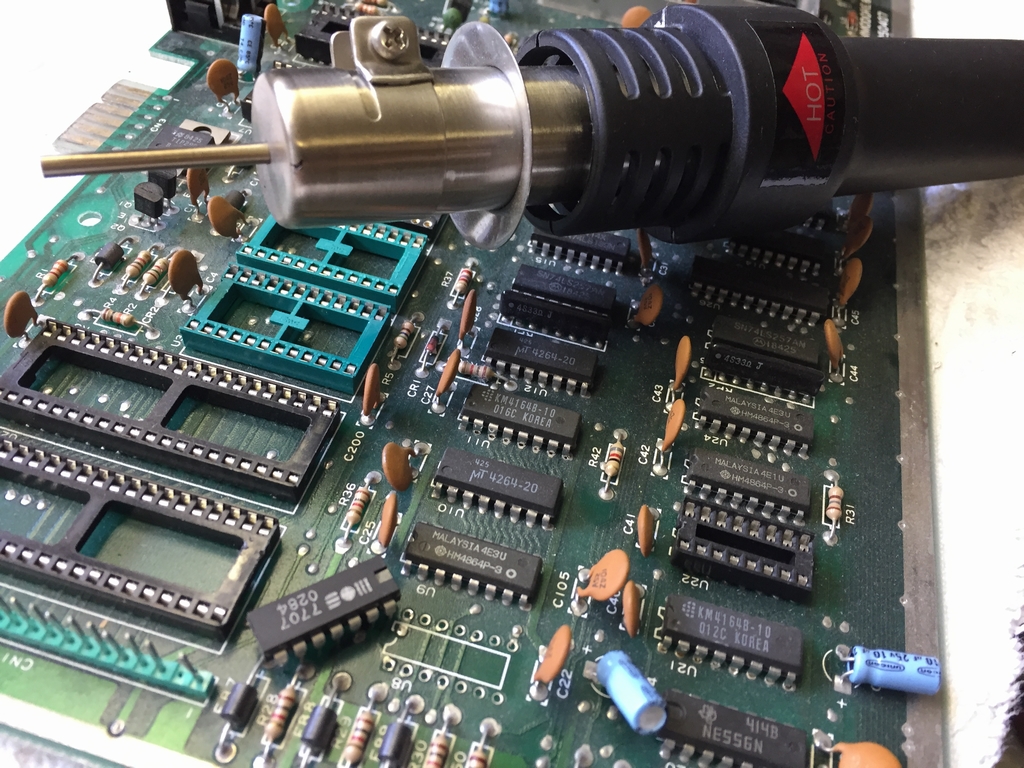
This chip is not a standard part of my spare parts, so I harvested one from a spare Assy 250425 board that I only use for parts. Using a air gun made it quite easy to remove the chip without bending any of its legs.
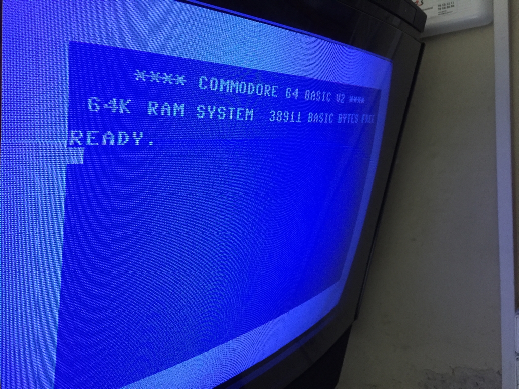
…and finally the sweet blue screen! However, the feeling of self-success only lasted a short while.
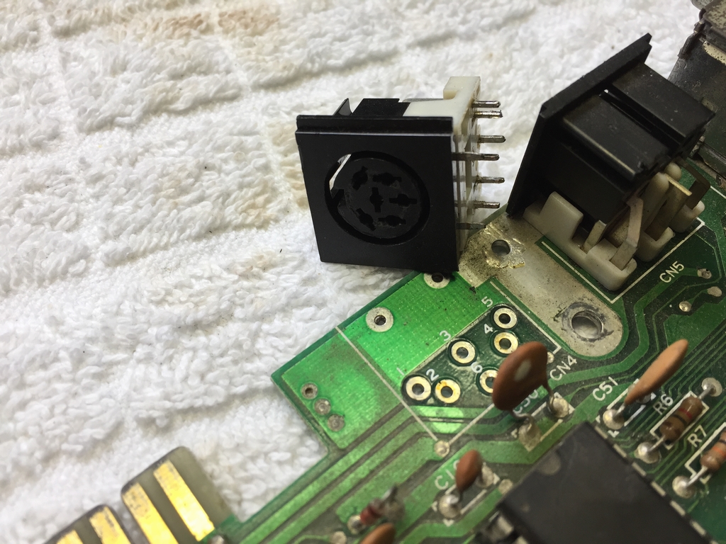
At first everything seemed to work perfectly until I mounted the serial plug tester that came with my 64 Doctor cartridge. This would make the freshly installed U8 7406 chip get extremely hot after just a few seconds. This chip is closely related to the serial port which is used for connecting the diskette drive. This is an image of the 64 Doctor serial port test plug.
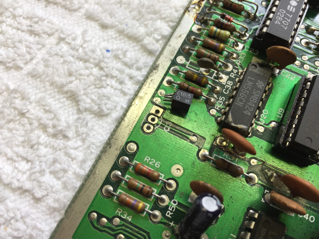
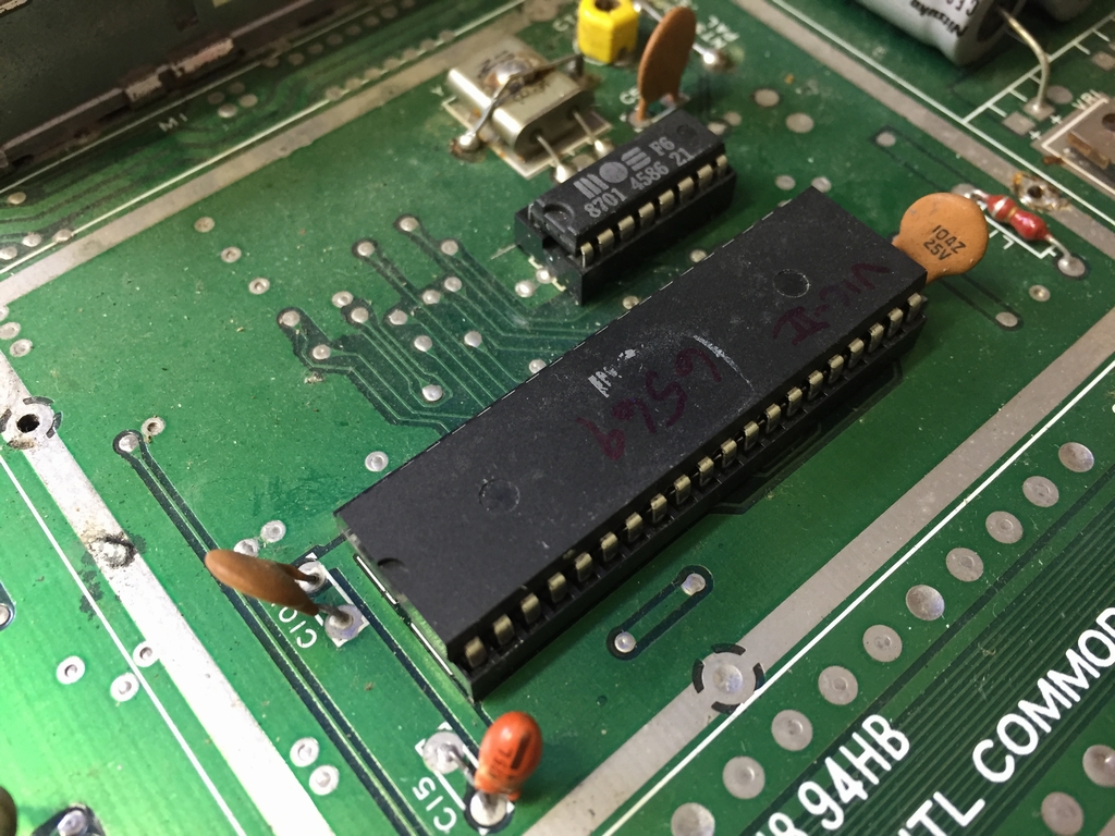
At this point I felt I was running out of options and basically started replacing chips ‘Kamikaze style’. I basically started swapping chips that may or may not be directly connected to the serial port. In this context, the 556 logic timer at U20 generates drive resets at powerup and was therefore also swapped with a fresh new one.
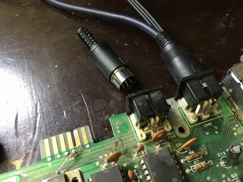
The 7406 chip was still burning hot. I therefore suspected that there was a fault in the female plug and exchanged it with one from a spare board I use for parts. This did not help either.
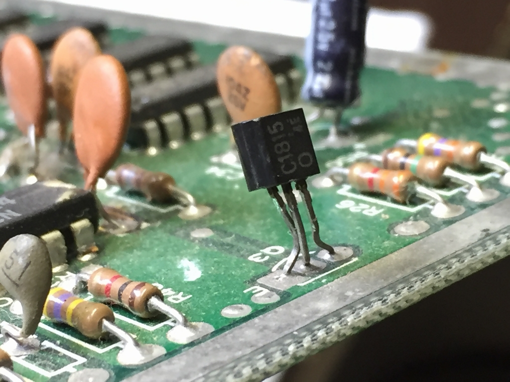
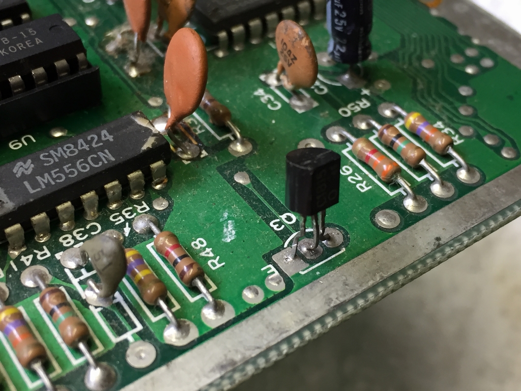
The transistor at Q3 may also affect the serial port if it is shorted. A closer inspection showed that transistor Q3 was indeed shorted! In with a new one from the spare board.
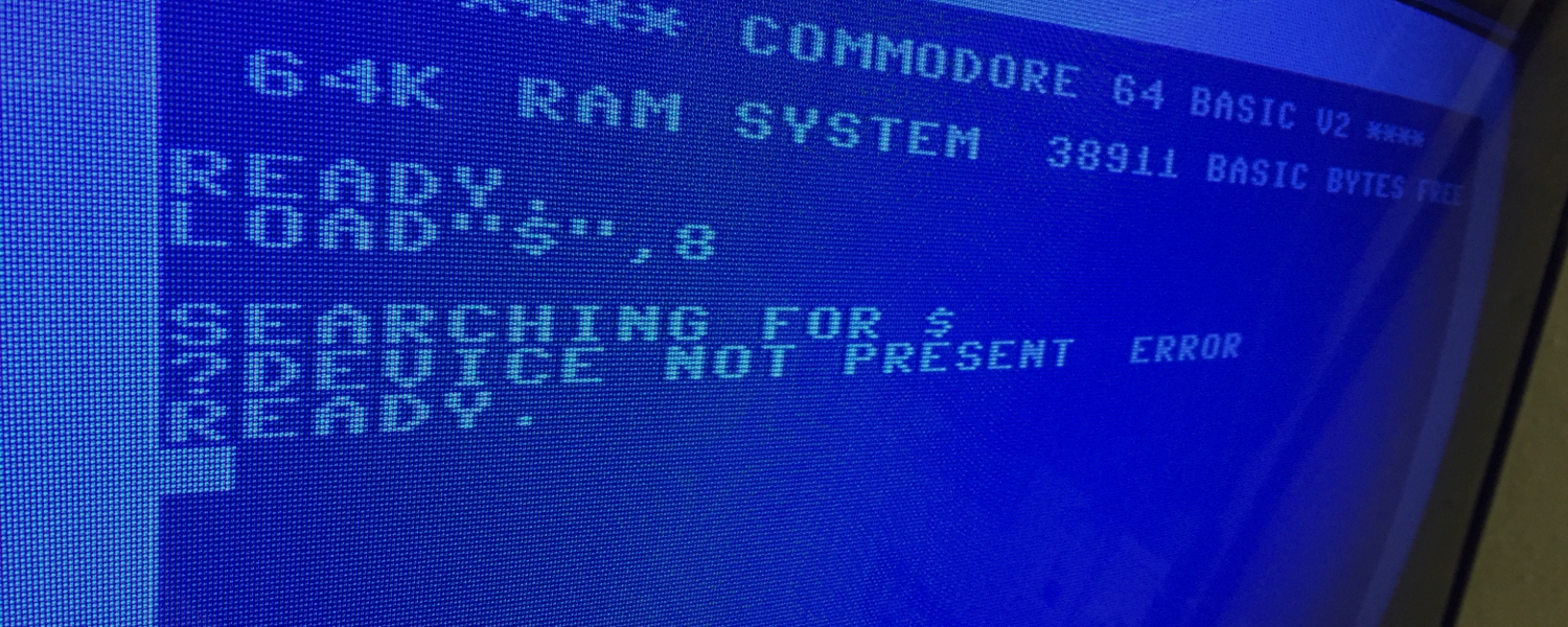
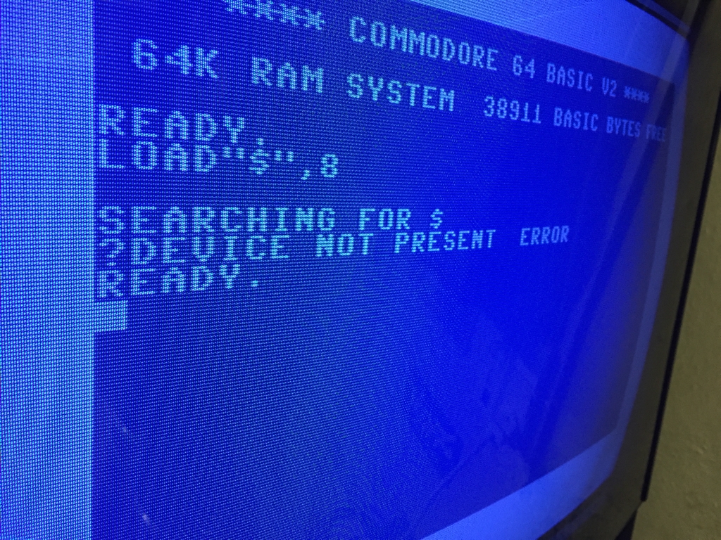
Still a hot 7406 chip at U8. After some serious neck scratching, I unplugged the 64 Doctor serial port tester and inserted my original Commodore 1541 diskette drive to the serial port to see if this would change anything. Trying to access the disk drive yielded a ‘DEVICE NOT PRESENT ERROR‘.
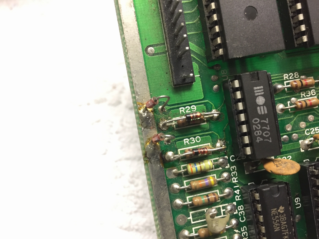
Now I was getting somewhere! I found the schematics of the serial port. Besides it’s close connection with the CIA chip at U2 and the 7406 chip at U8 it also contains 9 diodes that serves as a protection circuit of the serial bus. If the 7406 chip is broken, it may be caused by a broken protection circuit (more information can be found here). I knew the CIA chip was not faulty (nor the power plug that I’d also swapped), I therefore started measuring the diodes with the voltmeter of my multimeter. As the diodes are placed on the PCB, the values cannot be used for much more than faultfinding. However, I was looking for some kind of outlier in my measements and guess what? The diode above resistor R29 (CR100) was almost zero volts compared to the rest of the diodes (they had values of 1.2-0.5 V). Before starting up my soldering iron, I double checked the voltage of the same CR100 diode on another Assy 250245 board that I knew was working – and the diode seemed to be shorted! I therefore exchanged it with one from the spare board I only use for parts. The shorted diode (1N4148 or IN914) was soldered on top of resistor R29.
…and finally, everything was working again! I had access to the serial port (the diskette could be reached with a simple ‘LOAD”$”,8’ command) and the 7406 chip at U8 did not get burning hot anymore! I then put back the MPU, the SID, the PLA and the VIC-II one by one to see if they were faulty and they were all working.
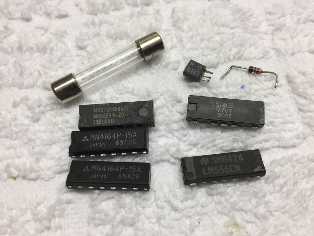
The repair included three RAM chips, a fuse, a 556 logic timer, a transister, a 7406 output driver and a diode.
© breadbox64.com 2017
Hey, I’m hunting down the infamous “?Device not present error”. Would you guess that it is caused by the diodes alone?
I’m buying 1n4148 diodes from elfa. Does it matter if they are specified to handle 100v or 75v?
Would you give me some details about that other diode type ‘cr-100’ and where on the board does it sit and would you send a link to new ones or a datasheet?
I kinda knew about the diodes, but I never saw what type pople are referring to (the 1n4148).
Thanks for this gold mine web site
//Ola
The ‘?Device Not Present Error’ fault can be caused by numerous things. You can find a nice overview here (link).
Diodes CR9, CR12-16 and CR100-105 are all of the same type – 1N4148 or 1N914. Either of the voltages you refer to should be fine as this is well above what they will ever be exposed to 😉 The schematics can be found here (link).
The CR100 sits above resistor R29 as seen in this image (link).
Good luck fixing the ‘?Device Not Present Error’ 🙂
I wonder what the function of the 1N4148 Diodes are on the left side of the board and on the top just above Q1 and a bit to the right of that, those diodes do not appear in the schematics from the repair manual.
Or does someone have schematics of this assy?
Hi Marco, the diodes are a protection circuit for the serial bus. You can find more information on the matter here: link
Hello, thank you for posting these very informative blogs. I wanted to quickly ask whether the rectangular trace around that surrounds the vic II chip and clock circuit impact the operation of the C64. I know in the older revisions the RF cage use to sit on top, but in the later models with no RF cage, I’m not sure if the trace has a purpose. Similar to your picture 4, my trace has corrosion, and one section has completely lifted and broken continuity. It does not appear to impact operation, but I wanted to check with you to whether I should try to repair the trace. Thank you.
Hi Diego, thank you for your kind words. I believe that the metal cage is primarily for cooling the VIC-II chip and not so much for RF shielding. The rectangular trace is connected to ground, so as long as the metal cage is still soldered somewhere to the trace, I’m sure your machine will be fine 🙂