
This is the source code used for the Switchless Reset Mod. Double click to enable plain text view of the code.
/*
Version 1.01 (updated October 18th 2017)
Purpose:
Switchless warm/cold reset system for the Commodore 64
Warm reset:
Clears any BASIC program stored in memory and resets the computer back to the opening blue screen
Cold reset:
If an extended pulse is applied to the /EXROM line at reset time, any machine language program will
clear and resets the computer back to the opening blue screen.
Function:
If RESTORE button is pressed for 2-4 seconds -> RESET line LOW (Warm Reset)
If RESTORE button is pressed for 4-10 seconds -> RESET line LOW & /EXROM line LOW for 300ms extra (Cold Reset)
If RESTORE button is pressed for >10 seconds -> nothing happens
Hardware:
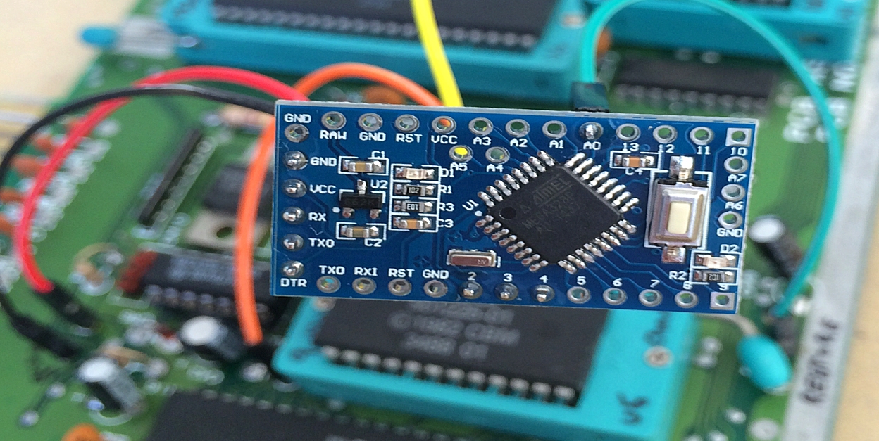
Arduino Pro Mini, ATmega328 (5V, 16MHz)
Disclamier:
Tested on short boards (Assy 250469) & long boards (Assy 250425)
Assumed to work across all motherboard versions
Use at your own risk!
Updates / credits:
Pinmode of RESET line is held as INPUT until requested to pull it LOW during Reset. This is to keep the Arduino
from constantly driving the reset line (thanks bwack)
Pinmode of /EXROM line is held as INPUT until requested to pull it LOW during Reset. This is to support cartridges
like the Final Cartridge III (thanks Gohanks)
By MtnBuffalo/breadbox64.com 2017
*/
// Constants
const int RESTORE_button = A0; // pin A0 is connected to the RESTORE button (analog input pin)
const int RESET_line = 3; // pin 3 is connected to the RESET line (digital output pin)
const int EXROM_line = 4; // pin 4 is connected to the /EXROM line of the PLA (digital output pin)
const int press_time_warm = 2000; // time in milliseconds before a warm reset is initiated
const int press_time_cold = 4000; // time in milliseconds before a cold reset is initiated
const int voltageValue = 100; // ADC value that will trigger the timer (voltages less than 0.5V) -> RESTORE pushed
// Variables
unsigned long RESTORE_press_time = 0; // the time the RESTORE button is being pressed in milliseconds
unsigned long StartTime = 0; // first time stamp for calculating RESTORE_press_time
int firstpress = 1; // test if the RESTORE button has been pressed
int analogValue; // ADC value (0-1023) read from the RESTORE button
// Functions
int debounce(); // debounce function to get ADC value (analogValue)
void setup()
{
//initialize digital pins
pinMode(RESET_line, INPUT); // digital pin 3 on the Arduino Pro Mini - Set as OUTPUT before warm/cold reset
pinMode(EXROM_line, INPUT); // digital pin 4 on the Arduino Pro Mini - set as OUTPUT before cold reset
digitalWrite(RESET_line, HIGH); // initial RESET_line state
digitalWrite(EXROM_line, HIGH); // initial EXROM_line state
pinMode(RESTORE_button, INPUT); // analog pin A0 on the Arduino Pro Mini
analogReference(DEFAULT); // setting the analog reference to 5V
}
void loop()
{
analogValue = debounce(); // call debounce function to get average ADC value
if(analogValue < voltageValue) // checks if the RESTORE button has been pressed
{
// initiate RESTORE push timer
if(firstpress == 1)
{
firstpress = 0;
StartTime = millis(); // first time stamp
delay(2); // make sure that RESTORE_press_time will become > 0 milliseconds
}
RESTORE_press_time = millis() - StartTime; // variable holds total time RESTORE is pressed
}
else if(firstpress == 0) firstpress = 1; // RESTORE button has been released
// Warm reset
if (firstpress == 1 && RESTORE_press_time > press_time_warm && RESTORE_press_time < press_time_cold)
{
pinMode(RESET_line, OUTPUT); // set as output to pull down the reset line
digitalWrite(RESET_line, LOW); // anode side of CR5 diode (Assy 250469) or pin 3 of User Port (Assy 250425) LOW
delay(200);
digitalWrite(RESET_line, HIGH); // reset RESET_line
RESTORE_press_time = 0; // reset timer
pinMode(RESET_line, INPUT); // reset the RESET line
}
// Cold reset
else if (firstpress == 1 && RESTORE_press_time > press_time_cold && RESTORE_press_time < 10000) //cancel reset if RESTORE is pushed > 10 seconds
{
pinMode(RESET_line, OUTPUT); // set as OUTPUT to pull down the reset line
pinMode(EXROM_line, OUTPUT); // set as OUTPUT to pull down the /EXROM line
digitalWrite(RESET_line, LOW); // anode side of CR5 diode (Assy 250469) or pin 3 of User Port (Assy 250425) LOW
digitalWrite(EXROM_line, LOW); // /EXROM line of the PLA LOW
delay(200);
digitalWrite(RESET_line, HIGH); // reset RESET_line
delay(300);
digitalWrite(EXROM_line, HIGH); // reset EXROM_line
RESTORE_press_time = 0; // reset timer
pinMode(RESET_line, INPUT); // reset the RESET line
pinMode(EXROM_line, INPUT); // reset the /EXROM line
}
}
// Debounce function to filter transistions/noise of the analog reading
int debounce()
{
int x, meanADC, sum = 0;
for (int i = 0; i < 5; i++){ // reads ADC value from pin A0 5 times
delay(5); // debounce for 25 ms total
sum += analogRead(RESTORE_button);
}
x = sum / 5; // mean ADC value
(x < voltageValue) ? (meanADC = x) : (meanADC = 1023); // if/else check - has RESTORE been pushed?
return meanADC; // return mean ADC value to main loop
}
NOTE: This article has also been been published in Europe’s #1 C64 scene disk magazine – Attitude #17 by TRIAD (link).
© breadbox64.com 2016
Regarding the 1.2V read on the RESTORE line. The RESTORE line is pulled up by 1 mega ohm, so you have to make sure that the arduina/atmega’s input impedance is high enough to not cause a voltage division there. I think you solved it, but if you can’t, then amplify it with a bc547 or a 2n7000 (nmos).
In the code I can’t see that the pinmode for reset is put back into INPUT mode. In other words, the arduino is constantly driving the reset line. The C64 is the one who pulls up the reset to 5V via a 1k resistor. After your code has pulled down the reset, put the pinmode back into input mode such that other devices who issue ressets (like cartridges etc) don’t send large currents from its driver into the driver inside the arduino.
Other than that, fascinating project !!
Hi there and thanks for the comments! The 1.2V on the RESTORE line is still a mystery. I’ve only seen it on that particular board and not on any other of my machines. Changing the input pin to analog was the simplest fix I could come up with 🙂
You are absolutely right about the pinmode of the Reset pin! I was not aware of this – my bad 🙁 I’ve updated the code so the pinmode is set as INPUT by default. Whenever the Arduino is requested to pull the Reset line to LOW (for Warm or Cold resets), the pinmode is changed to OUTPUT. After the reset, the pinmode is set back to INPUT again. Good point!
I like the analog input solution. It works reliably in my machines. As for the cartridge compatibility, I had some issues with the code when used with Final Cartridge III. Solved it by putting the /EXROM line in input mode during normal operations and flipping it to output mode just before resetting the same way as the RESET line is handled. Now it works like a charm with every cartridge I tested it against. Also I’ve put in a rom selector in my version as well. Thx for a nice and useful article.
Hi Gohanks. Thanks for your comment! I never tested the Switchless Reset Switch with a cartridge inserted. I’ve updated the code according to your directions so it should work with carts as well – thanks! Sounds very nice that you’ve also added a ROM selector option using the Arduino 🙂
Hey, I’ve added this mod to my C64C 250469 rev. B but only warm reset is working. Cold reset does nothing else than warm one do (the screen doesn’t go black, only results similar to SYS 64738). I’ve double checked connections with multimeter, between pin 46 of U8 (PLA’s /EXROM) and pin 4 of Arduino. My C64 had capacitors replaced, can it be the cause ? I’m not using any cart.
Hi r1me, I don’t think the capacitors have anything to with your machine doesn’t do cold resets. I sounds more like the /EXROM line is not being pulled LOW for some reason as the warm reset works (RESET line goes LOW). I used this soldering point (link) on an Assy 250469 short board for the /EXROM line. Is this point connected to pin 4 on your Arduino?