
It has been a while since I last worked on my mechanical keyboard project, the MechBoard64 (link). I have been wanting to add some lights to the keyboard for quite some time, but never got around to it. How cool would an illuminated MechBoard64 look inside a transparent C64C slim case (link) with some some new transparent keycaps on top (link)? Well, pretty cool I guess!!! I therefore decided to do something about it and added some light underneath each keycap. After a few late nights, I was finally ready to send off the updated printed circuit board (PCB) to production…
Below are the results of my efforts and how the The MechBoard64 Light Mod was created.
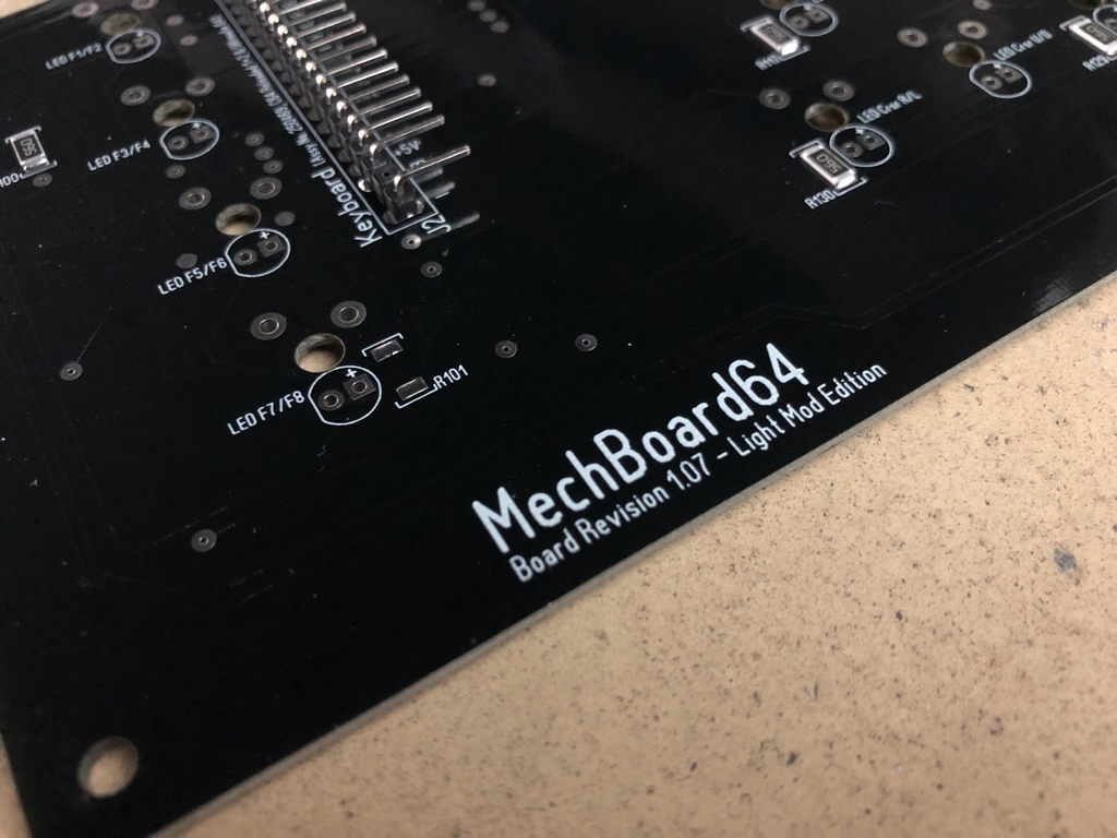
Updated PCB
I wanted to keep the functionality of the original MechBoard64 intact regardless of whether the LEDs are installed or not. Thus, the keyboard should function just fine without the added lights. As the Commodore 64 motherboard provides 5VDC to the keyboard, I simply added a 2 x 33 array for the 66 LEDs. Thus, the LED circuit does not have some fancy RGB circuit for controlling the LED colors or anything. It is just an array of LEDs in a serial/parallel configuration to control the voltage and power draw. Furthermore, each LED has to be soldered directly into the PCB. So it is as basic as it can be.
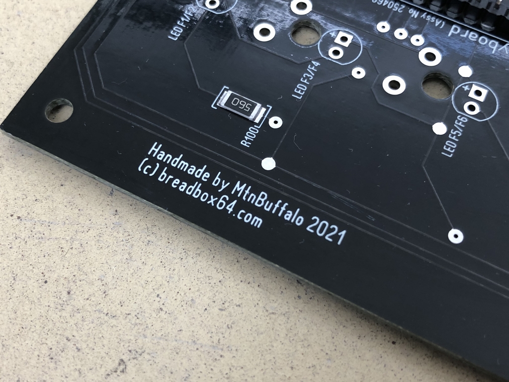
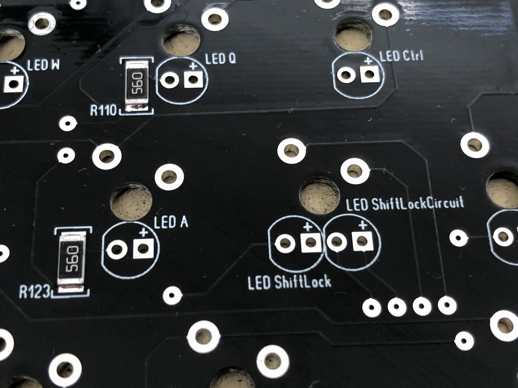
I aimed for a forward voltage of 2.0VDC to support most 3mm LEDs regardless of color. This is the same voltage that the ShiftLock circuit LED gets. In this context, e.g. blue and green LEDs usually support a forward voltage of about 3.0VDC while red colored LEDs only need around 2.0VDC. To keep things simple, I simply went with the lower voltage using 56Ω resistors. This way pretty much any LED, regardless of color, can be installed without worrying too much about LED specs. This will obviously reduce the amount of dissipated light from LEDs which can handle a higher voltage. But the goal had never been to get as much light as possible. I just wanted enough light to see the keycaps in the dark. It should be noted, that if e.g. 0Ω ‘resistors’ are used instead of 56Ω resistors, the forward voltage will increase to about 2.5V and hence increase the strength of the illumination. This will only work if the LEDs are rated at at least 2.5VDC.
I also did some power calculations of the array of LEDs along with the power loss across the resistors. To the best of my ability, I believe that that LED system draws roughly 3.38 W (1/4W resistors = 739mW & diodes = 2640mW). The circuit draws 660mW from the source (this will also be the case if using 0Ω resistors). Thus, the original C64 PSU cannot be used anymore! Very importnat to notice!! The original C64 power supplies only provide about 7.5-8.5W (1.5-1.7A@5VDC) and will most likely make the system unstable (link) if used! However, a modern-day PSU, like the one’s from Electroware yield 3-4A@5VDC depending on which model is chosen (link). So that type of PSU should work without any stability issues.
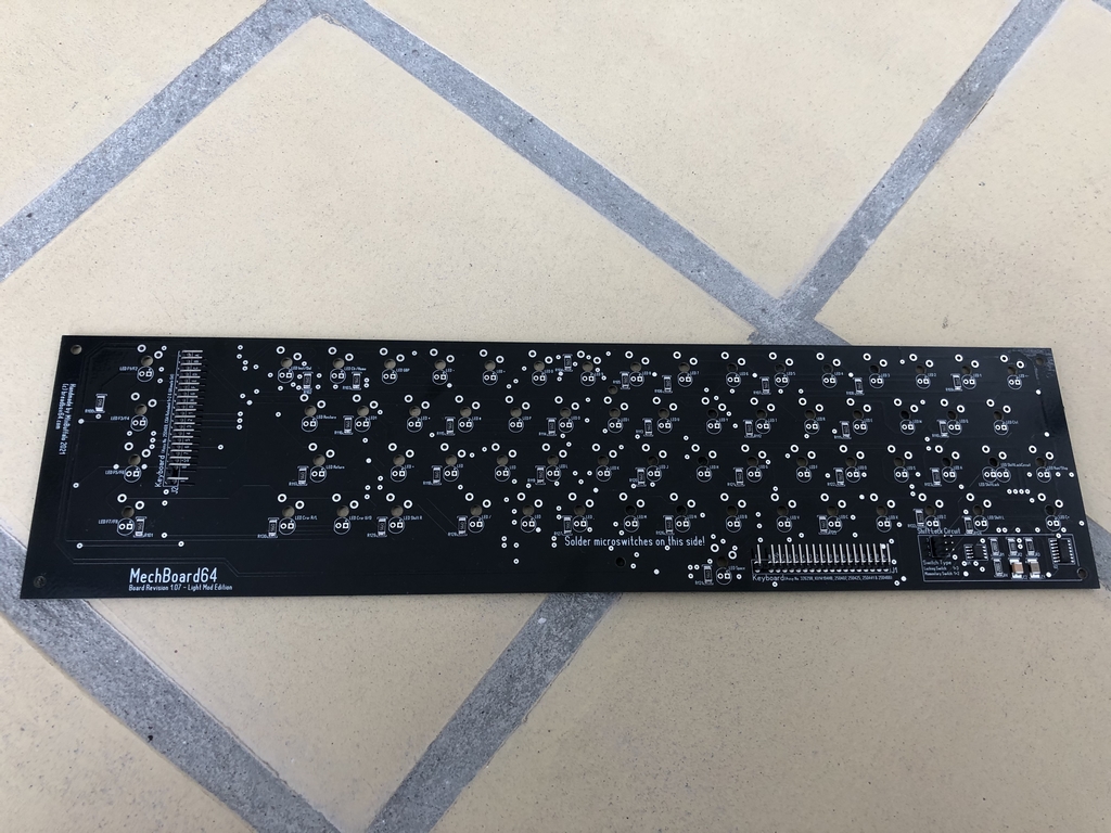
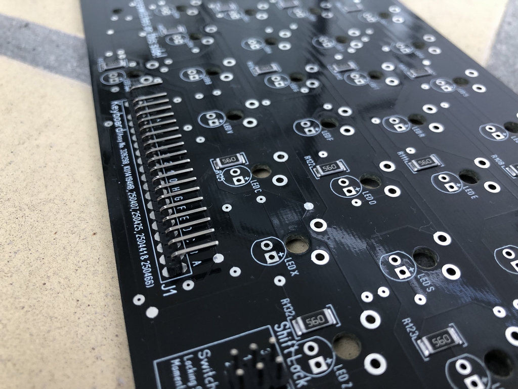
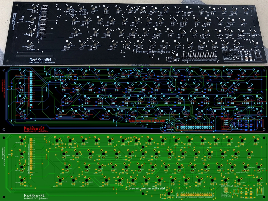
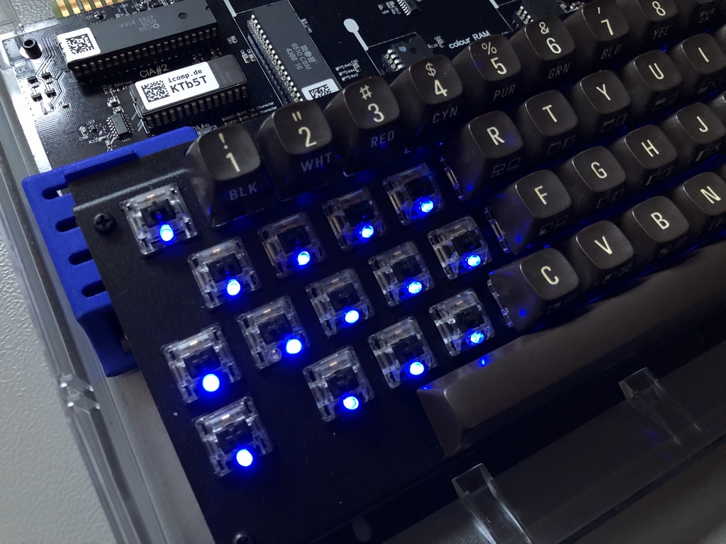
This is the finished PCB.
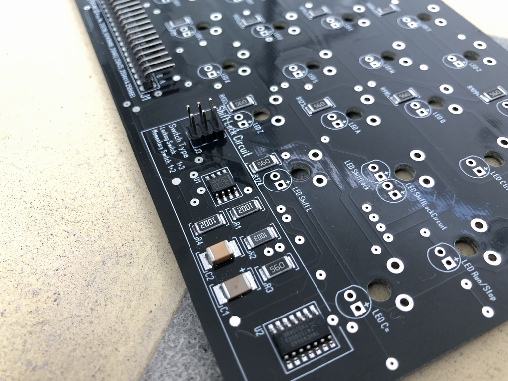
Updated ShiftLock Area
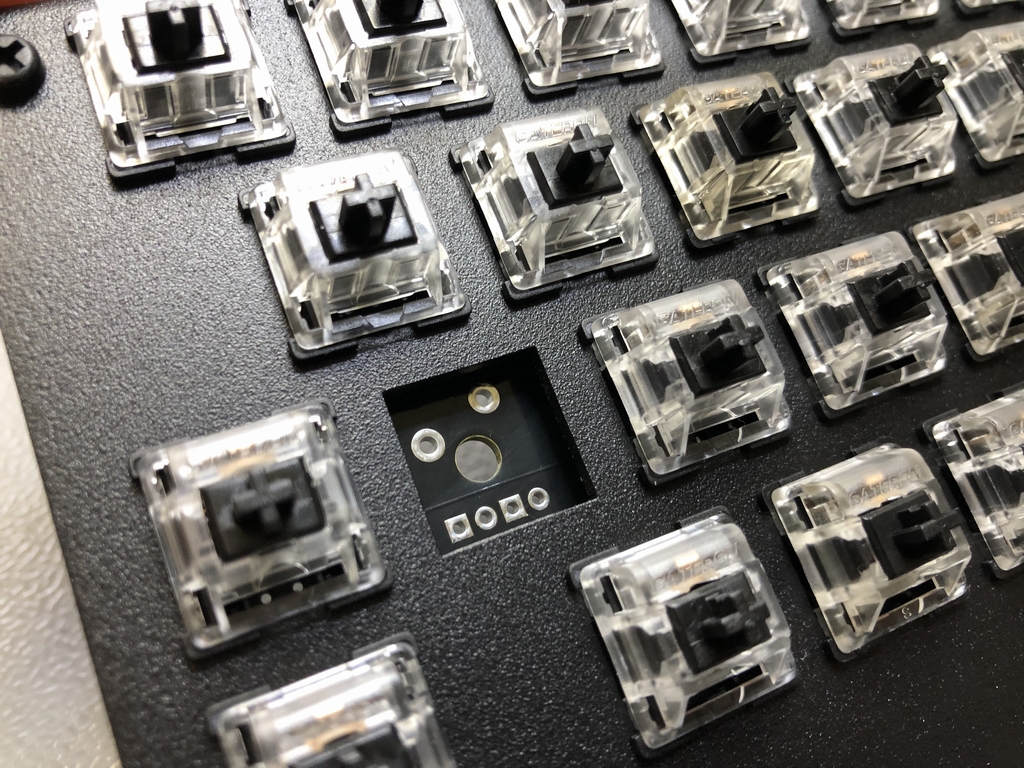
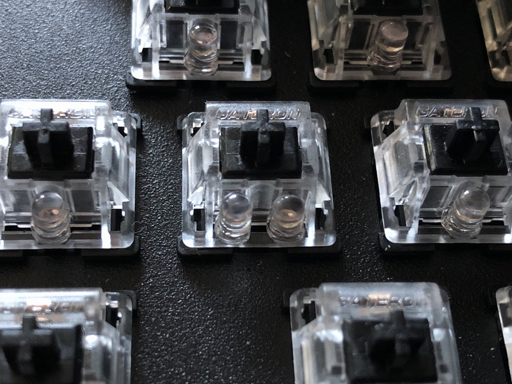
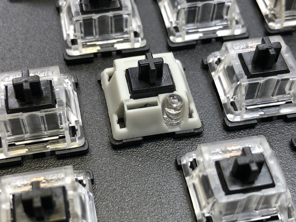
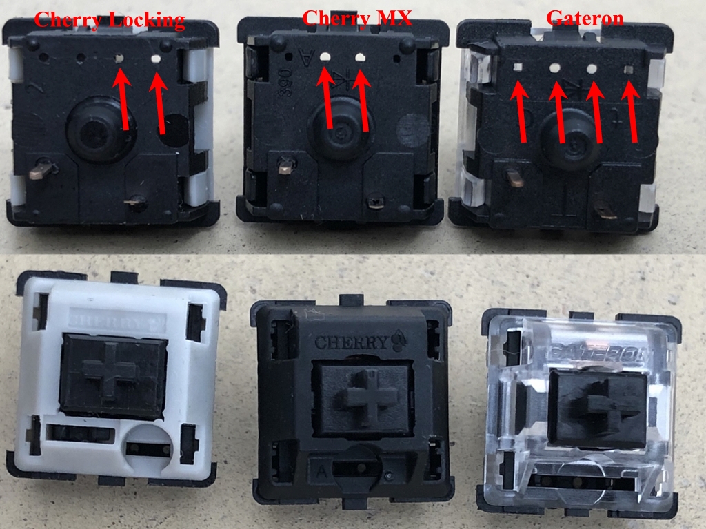
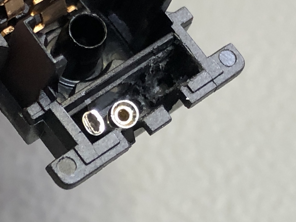
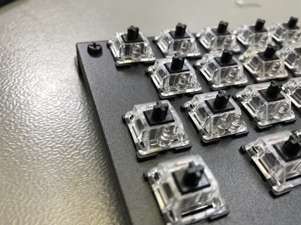
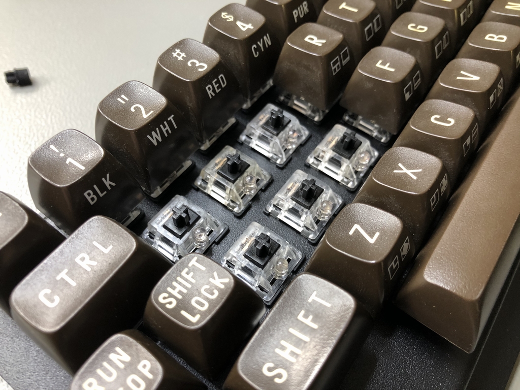
The PCB obviously had to be updated to accommodate an LED inside each microswitch. Furthermore, the ShiftLock area also had to be updated to contain sockets for an extra LED. One for the ‘permanent’ LED as the rest of the keyboard and one for the ShiftLock circuit (push on – push off circuit). In this context, Gateron switches already have four holes in the base for two LEDs. Cherry mx switches does not but can probably be made manually (I have not tested this!). But what about support for a Cherry Locking switch (link) if I want to keep things old school? In this context, Cherry Locking switches are latching switchces with identical functionality of the orignal Commodore 64 ShiftLock key. It turns out that these switches have a groove for an LED on their right side. I therefore placed the two sockets in a way that a Cherry Locking switch can be used with an LED to shine along with the rest of the keyboard.
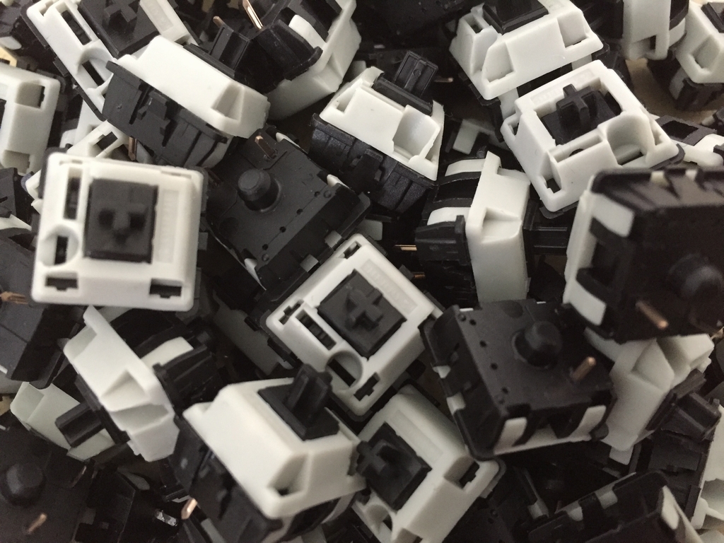
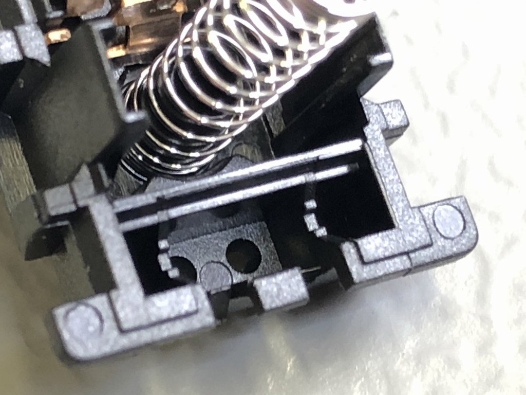
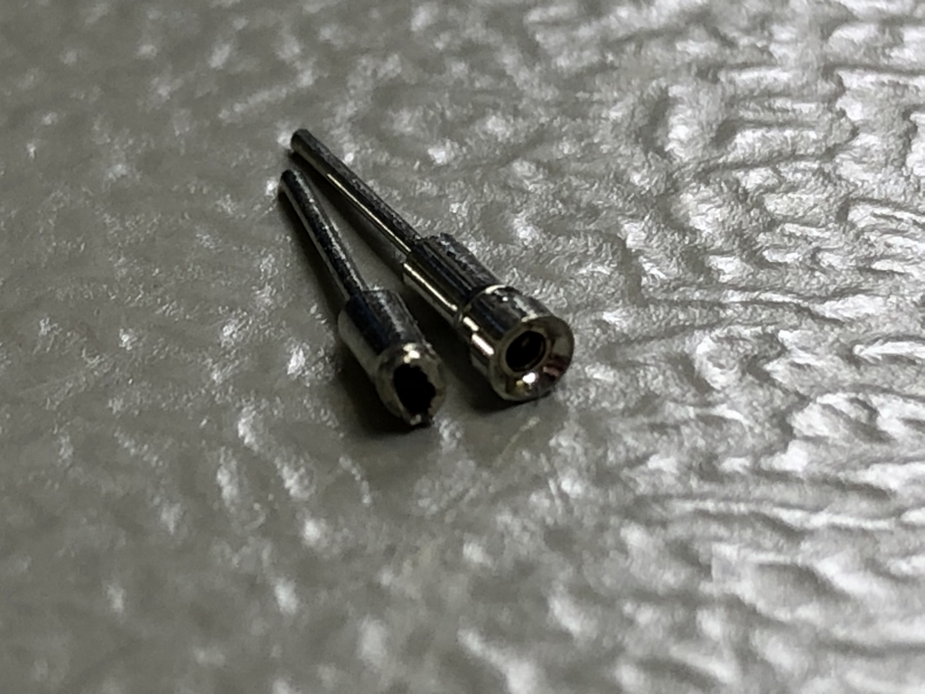
In my original MechBoard64’s (link) I have installed two SIP sockets inside the Gateron microswitch for the ShiftLock key. This way it is really easy to change the LED color as no soldering is needed. However, as seen below the Gateron switches have two ‘falanges’ on each side of the internal ‘LED area’. I have tried cutting them off and trimming down one of the SIP sockets to make them fit. However, the result was not great and the ShiftLock circuit LED would flash and be quite unstable. I therefore decided to simply not install the SIP sockets. The ratioale being that how often do I really want to swap color of the ShiftLock? I guess that would be like – never 🙂
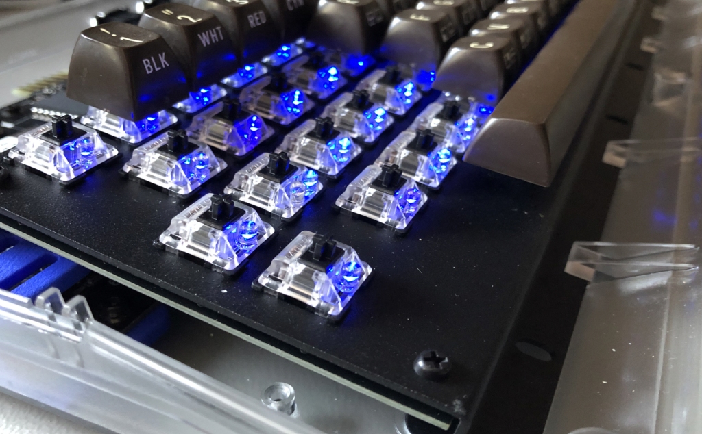
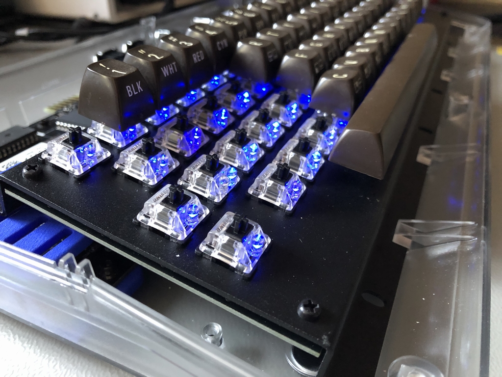
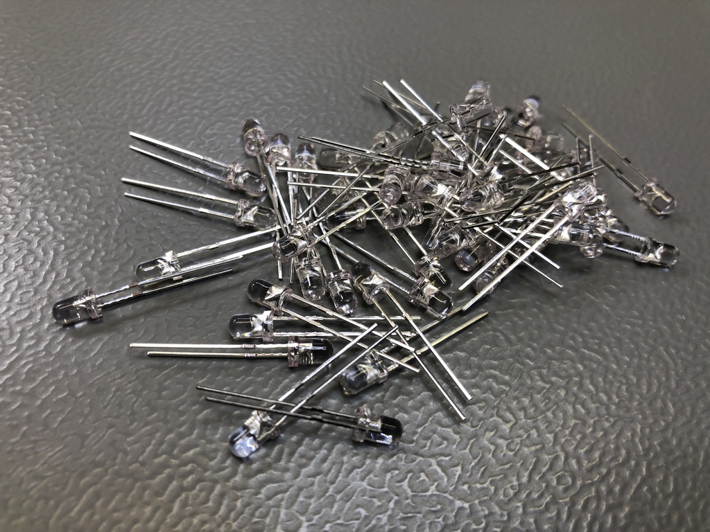
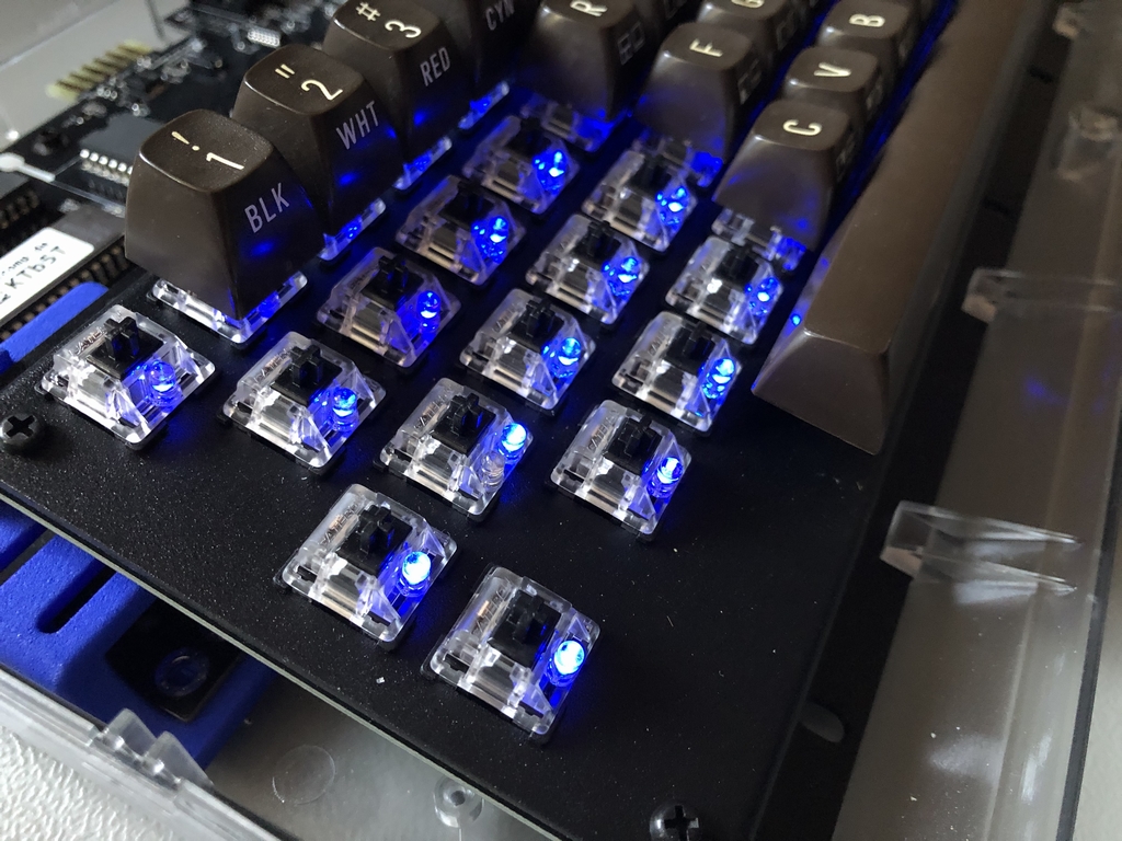
Mounting the LEDs
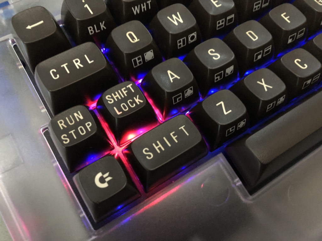
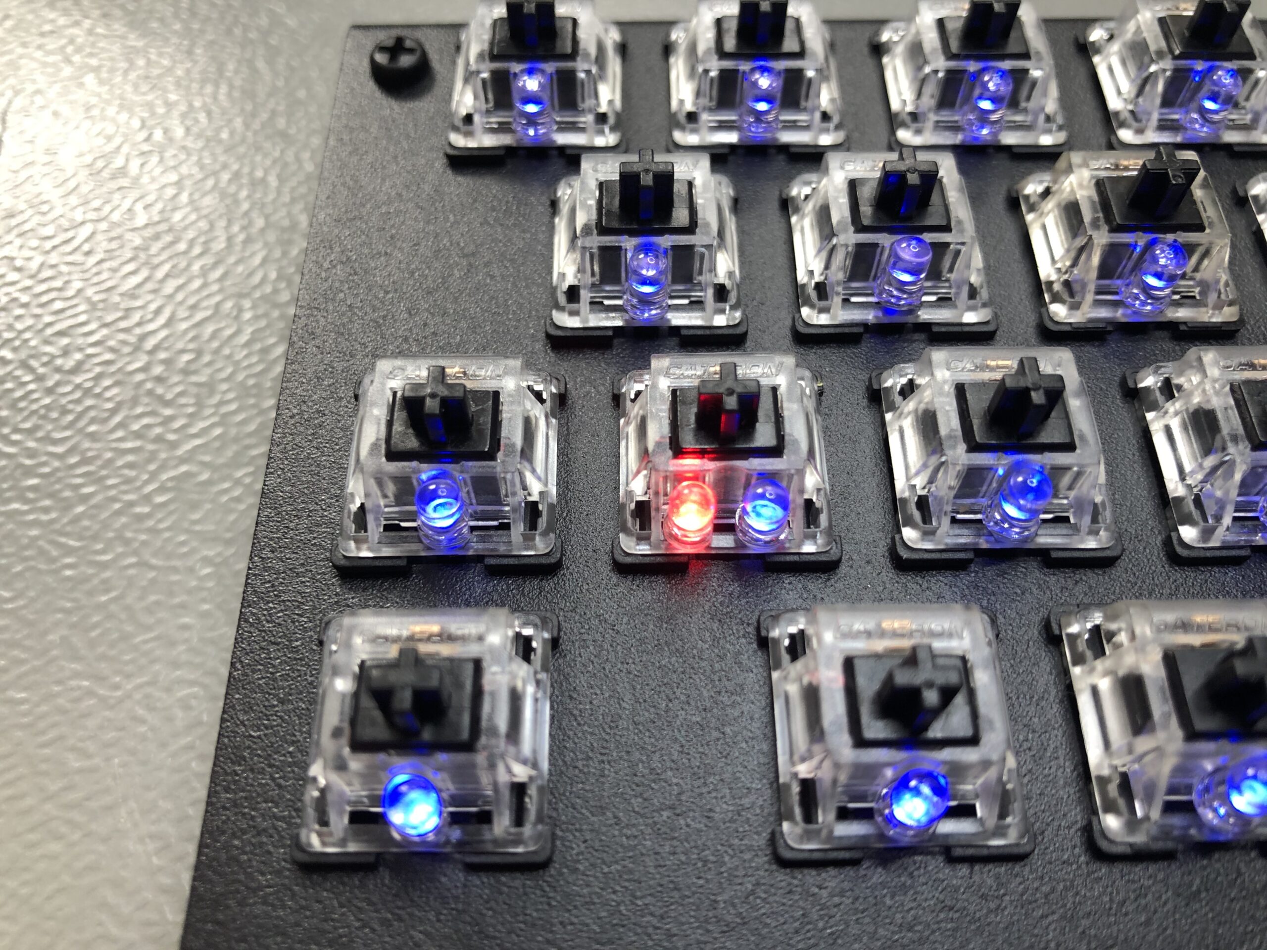
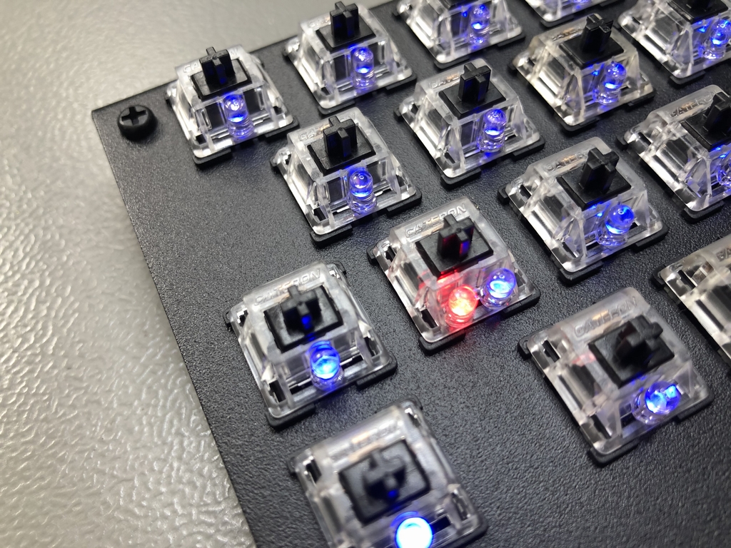
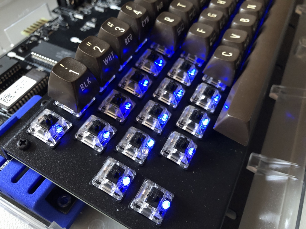
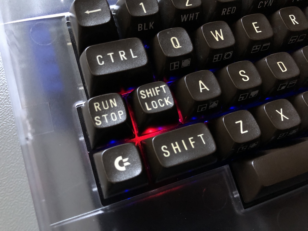
Next up was mounting the LEDs. I went with some blue LED as I really like that color. The ShiftLock circuit has a red LED installed. We want to be able to see when it is activated, right?
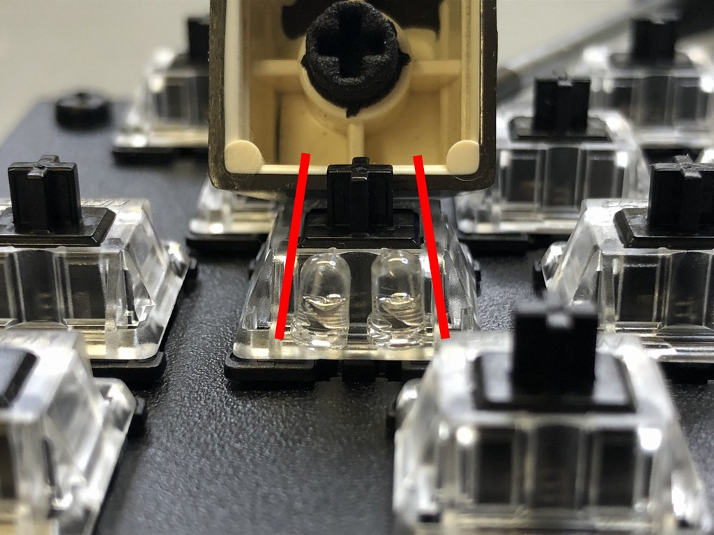
Fitting two LEDs underneath the SiftLock key turned out to be a really tight fit. The trick is to make them tilt slightly towards the center axis of the microswitch as shown below (red arrows). This way the ShiftLock key doesn’t get stuck unintentionally…
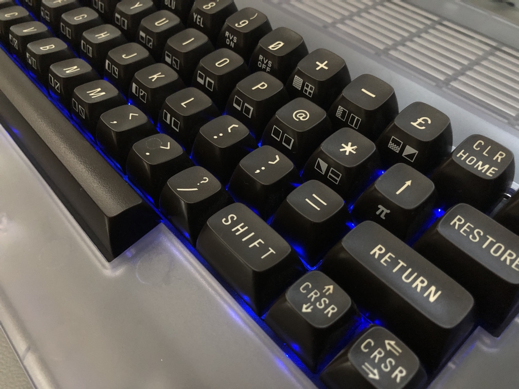
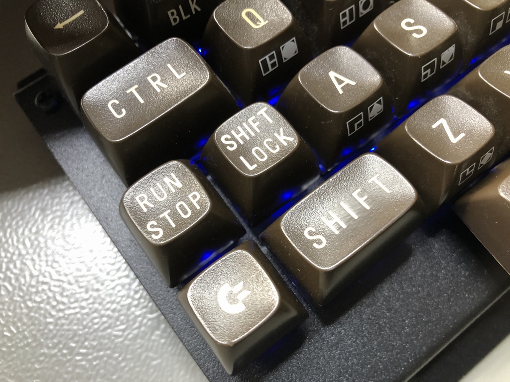
Adding Keycaps
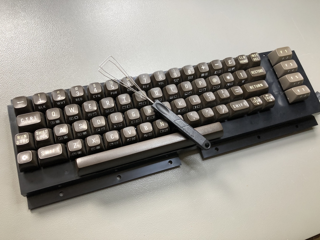
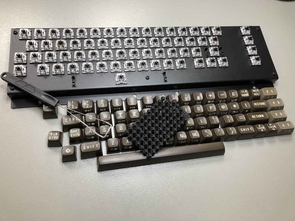
It was now time to add the last parts to finish off the keyboard. I had a donor C64 keyboard that I used. With the aid of a keycap puller and some 3D printed keycap adapters, the keyboard was finally ready for some testing…
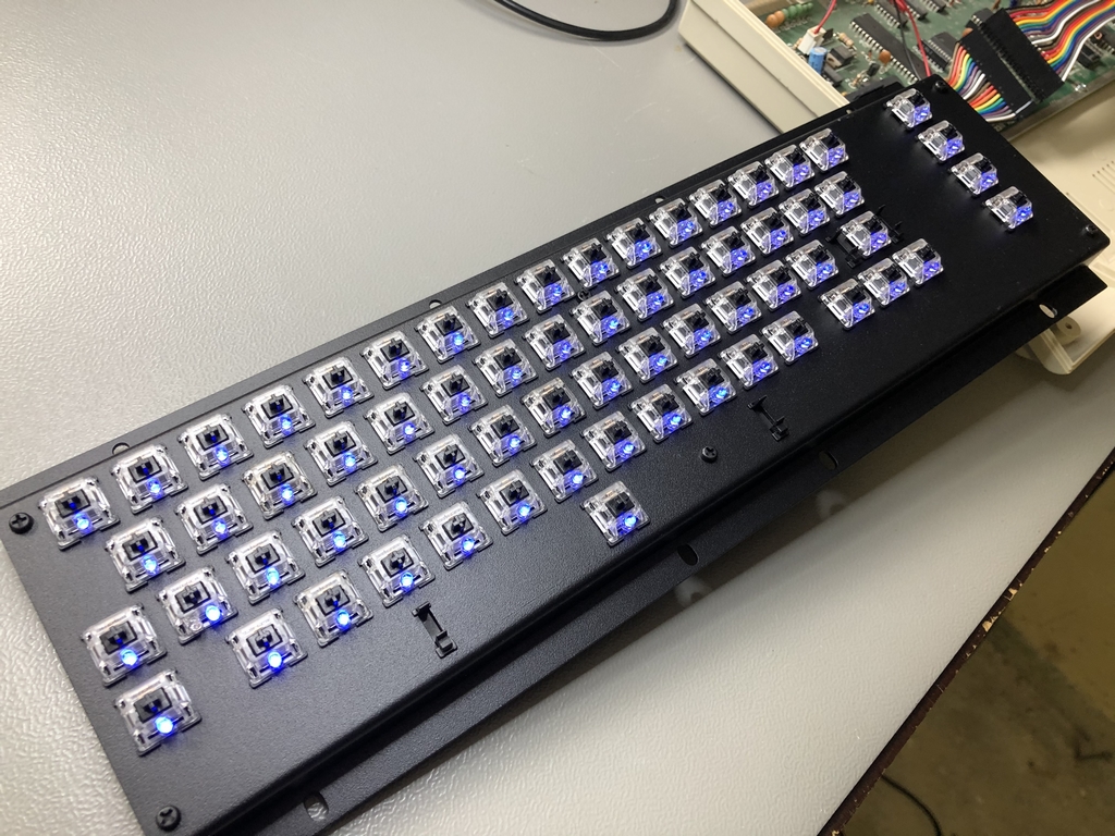
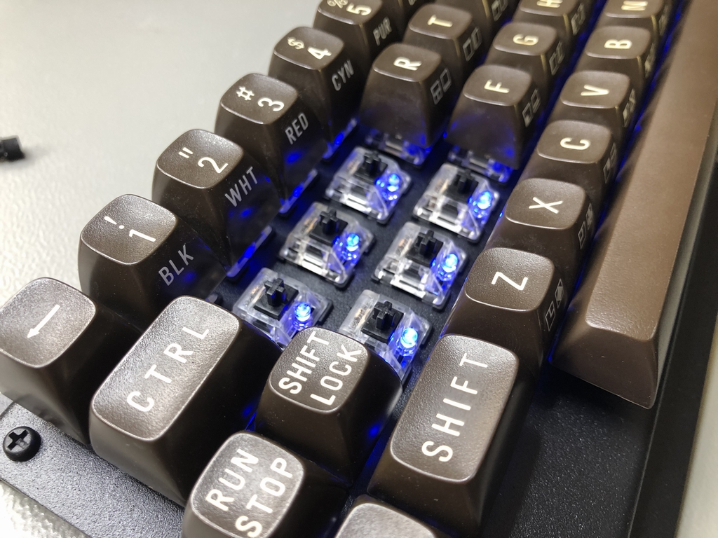
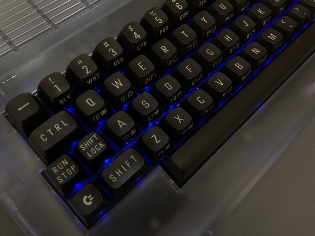
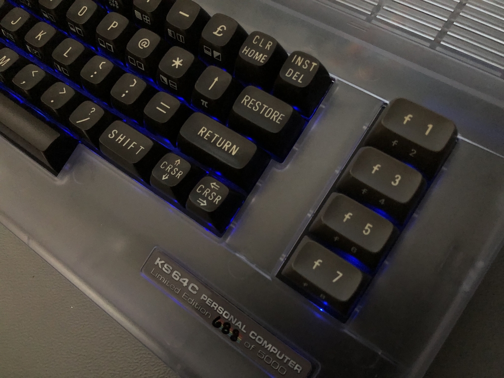
Finished Keyboard
And there was light! Well, I had four LEDs on the top corner that did not work right away… Pheeew, sweaty palms!! Luckily, it turned out that I simply forgot to solder them – shame on me! After re-checking everything, the new keyboard worked as is was supposed to. Nothing beats self-success, right? The LEDs turn on when the computer is turned on and the keyboard functions as it always has.

I plan to use the keyboard in my C64 Reloaded mk1 machines (link). Whenever I receive the new transparent keycaps from Jim Drew’s Indiegogo campaign (link) I will finally have a brand spanking new Commodore 64! Fingers crossed it will happen soon…
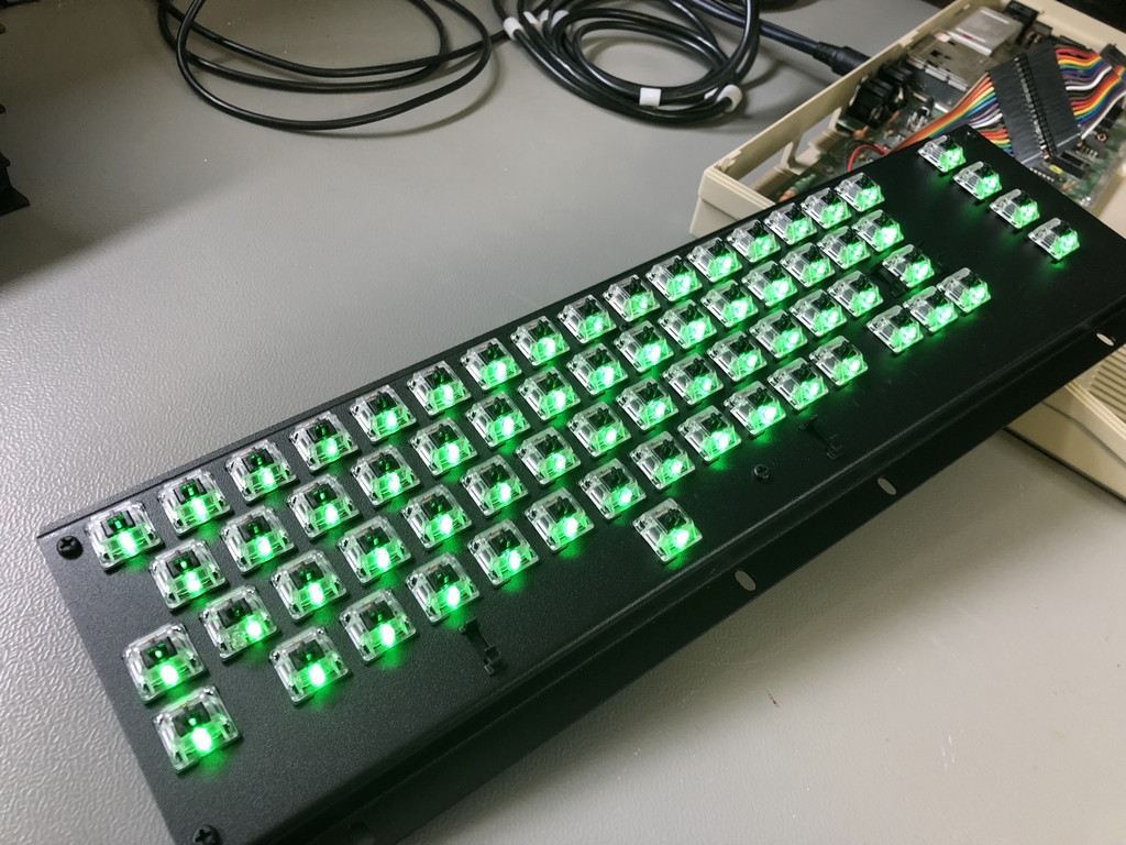
Other LED colors
UPDATE: if using LEDs with other colors and/or specifications, the brightness will obviously change. Here is an example of a MechBoard64 with green LEDs installed. They are really bright in comparison to the blue LEDs!!

Want to Make Your Own MechBoard64 Light Mod Edition?
More information and instructions can be found here (link).
© breadbox64.com 2021
Is it possible to use smooth light intensity control for all keys simultaneously?
It is not possible to use e.g. a potentiometer to increase/decrease the forward voltage of the LEDs. When installed, the LED circuit turns on when the computer is powered on. So there is no fancy light control or something like that. It is as simple as it can be 🙂
Yes, yes, but is it possible to use such a dimmer? For example something like that: link
I cannot see how it will work out of the box with just the extra hardware (Keymouse main PCB module). My guess is that the MechBoard64 would need to be wired differently to make it work. It also seems like a lot of work for adjusting the light intensity of the LEDs. But certainly possible. I wouldn’t personally want the solution to due to the extra hardware required. I like to keep things as simple as possible 🙂
If you want, you are more than welcome to modify the PCB. You can find the Gerbers here: link