
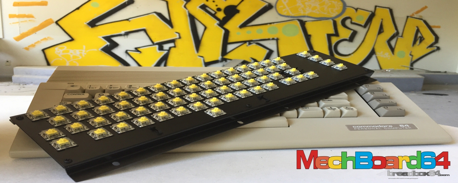
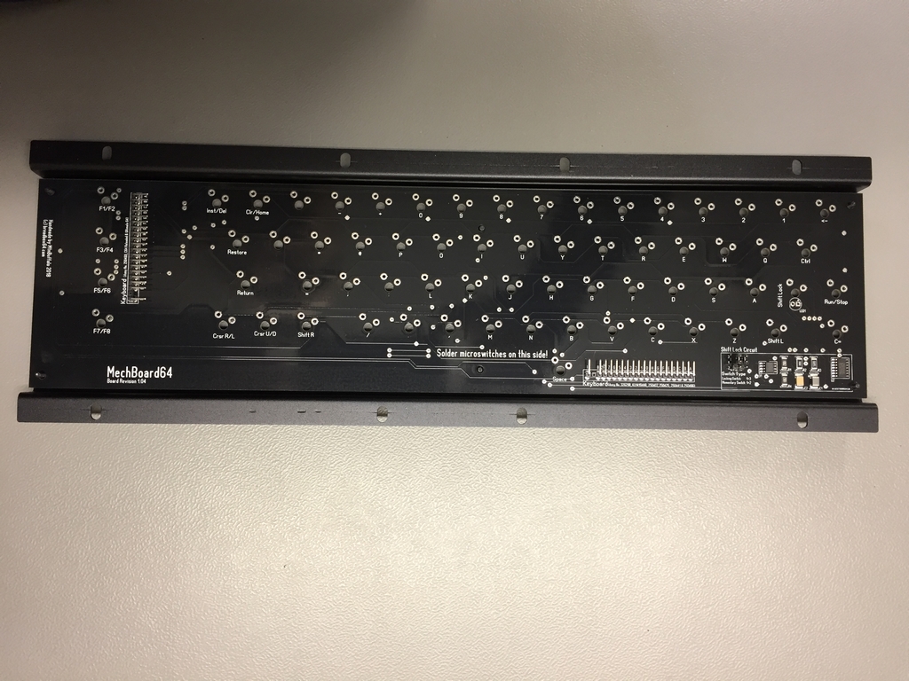
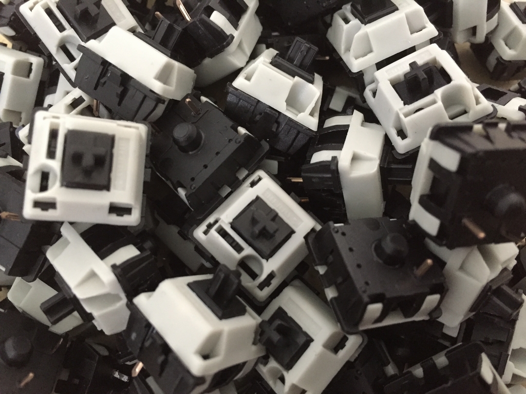
The MechBoard64 is a drop-in replacement for the original Commodore 64 keyboard. It should work in concordance with all the different C64 versions of motherboards available, including the new motherboards (C64 Reloaded mk I+II and the Ultimate64). The MechBoard64 consists of Cherry mx type microswitches, an aluminum bracket, a printed circuit board (PCB) and a multicolored ribbon cable for connecting the keyboard to the C64 hardware. The MechBoard64 also has a small electrical circuit that will add the functionality of the Shift Lock key but without the need for a latching microswitch like the Cherry Locking switch. Whenever the Shift Lock key is pressed, a bright LED will light up underneath the keycap to indicate its current state (on or off). Further details and heaps of images can be found here (link).
Keyboard Assembly
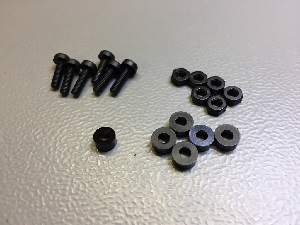
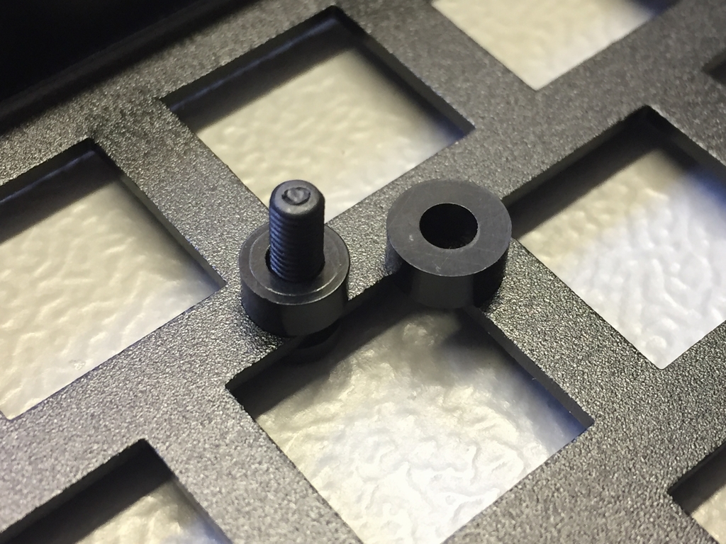
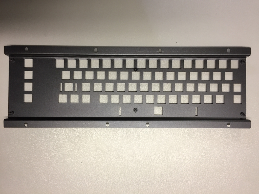
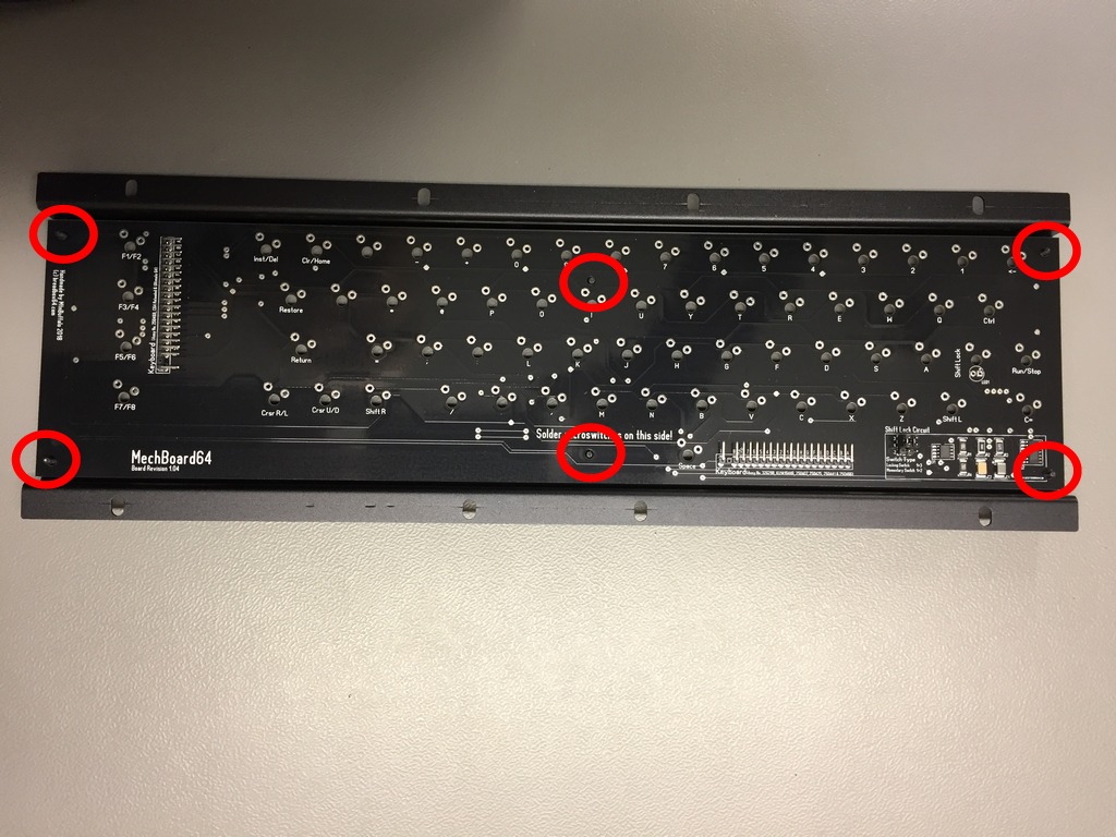
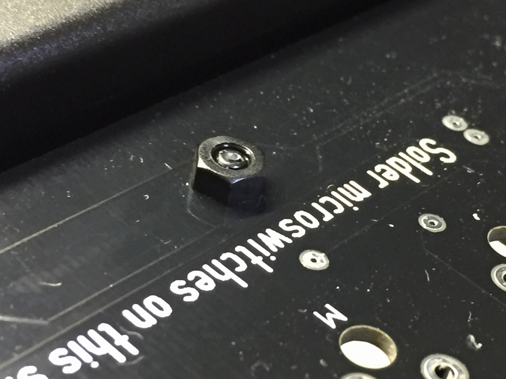
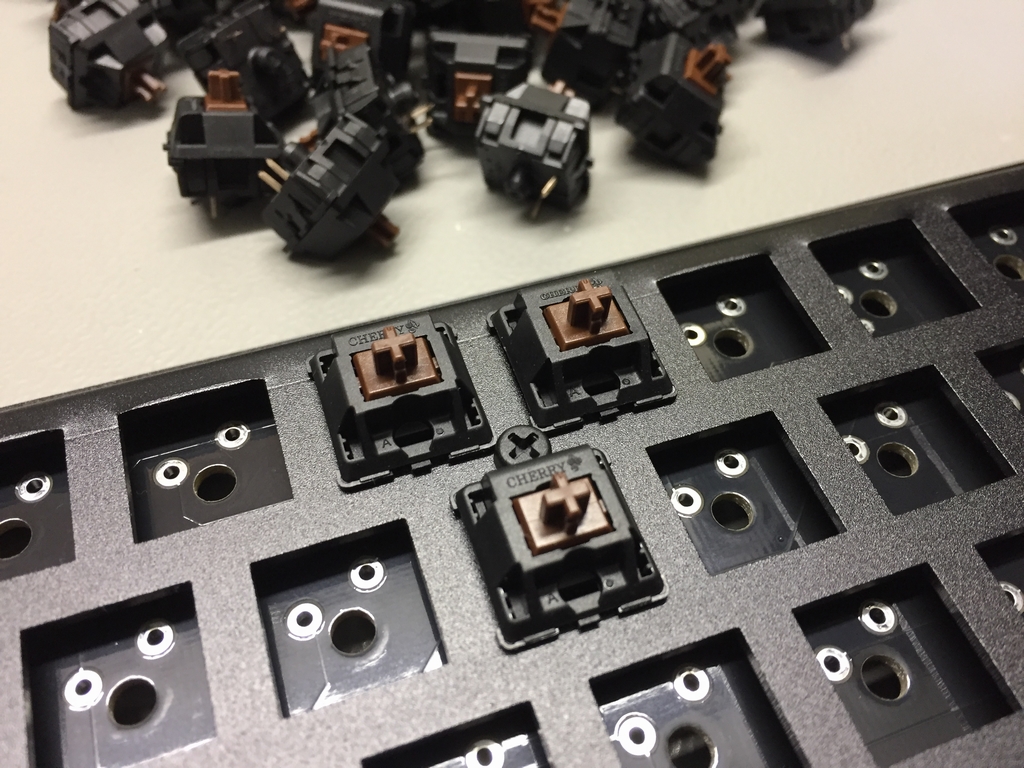
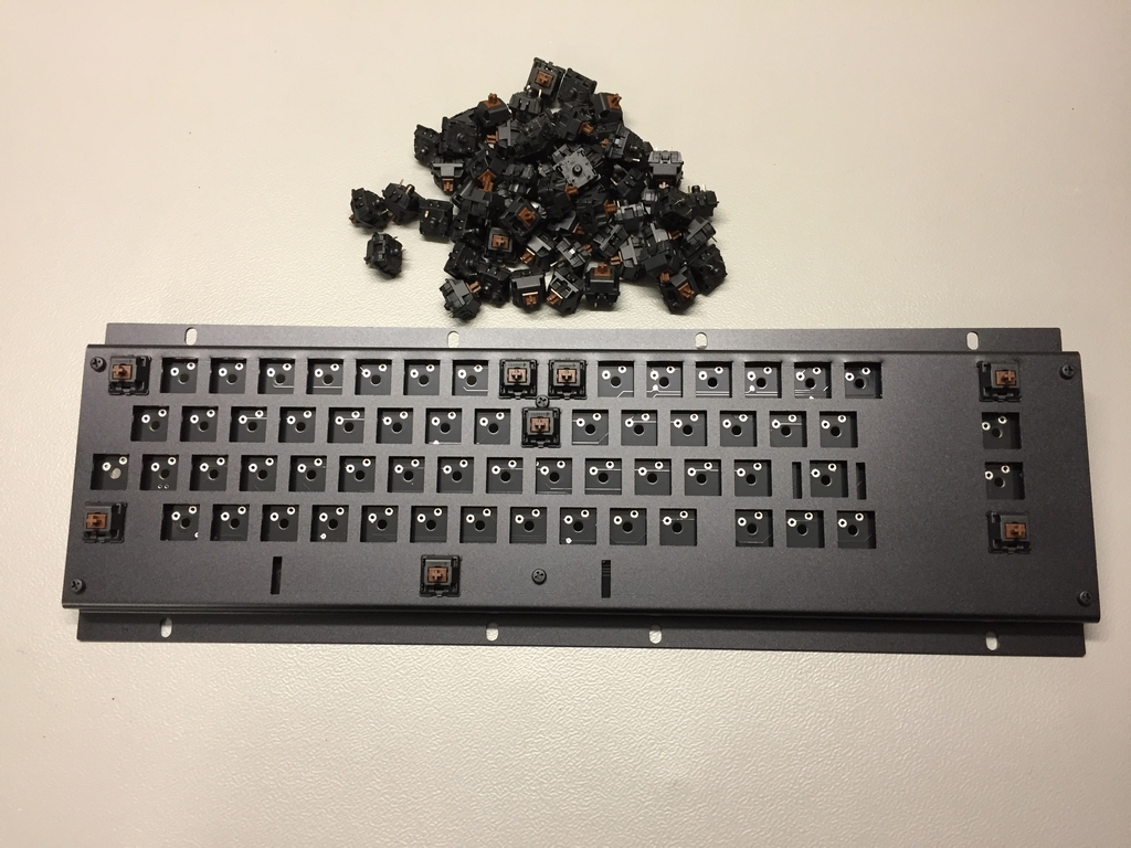
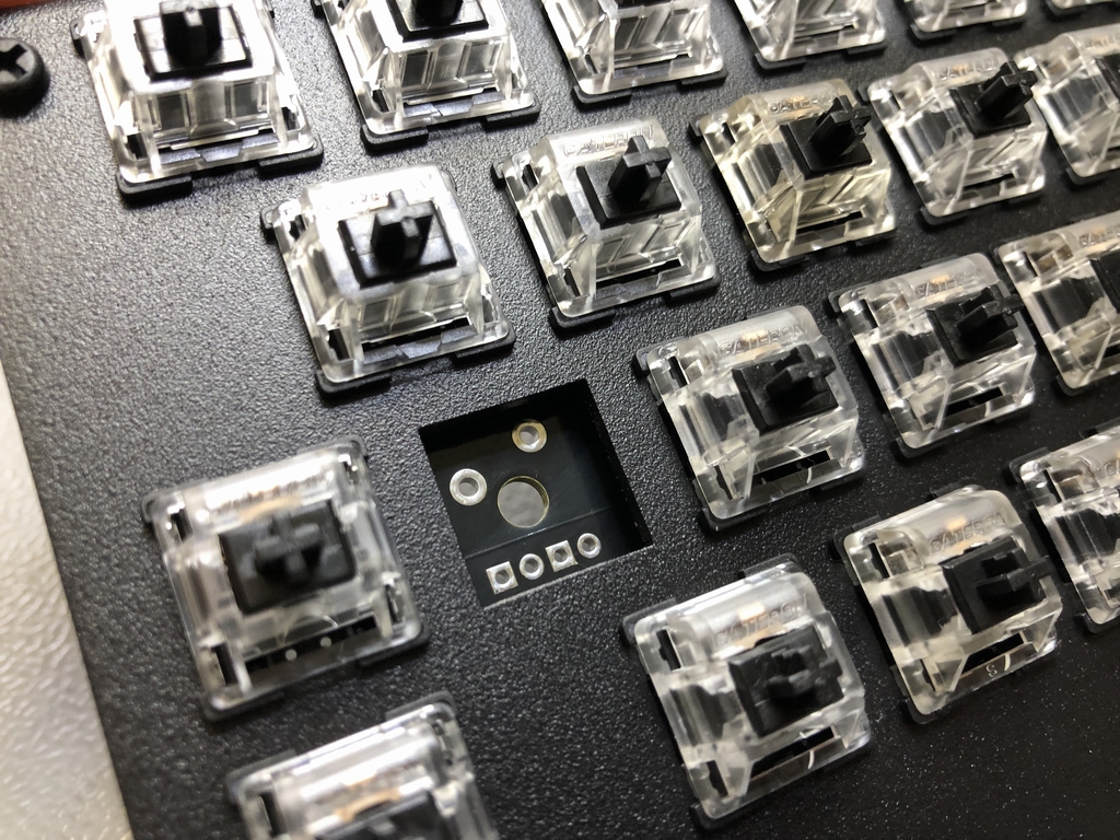
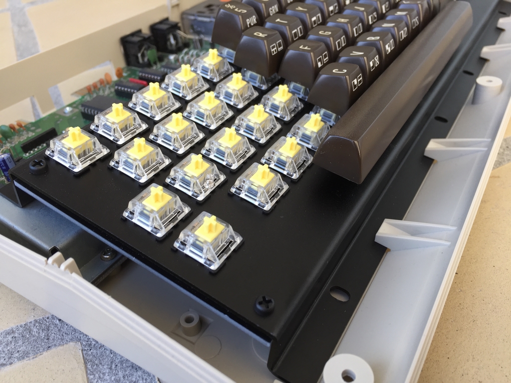
The PCB is attached to the aluminum bracket using six plastic M3 x 10 mm screws, six plastic M3 bolts and six plastic M3 x 3mm spacers (ø=6-7 mm). The spacer placed at the center of the top row must have a smaller outer diameter (ø=6 mm) in relation to the other five spacers (7 mm). This is because of the tighter space surrounding the spacer with microswitches. Start by loosening all six screws to make the PCB sit loosely in the frame. Insert the three microswitches surrounding the 6mm spacer and lightly tighten the screw. Then place microswitches in all corners of the aluminum bracket and lightly tighten all the screws. No need to use any force as they they are only used to guide the PCB. Insert the remaining microswitches and solder everything.
MechBoard64 Light Mod Edition
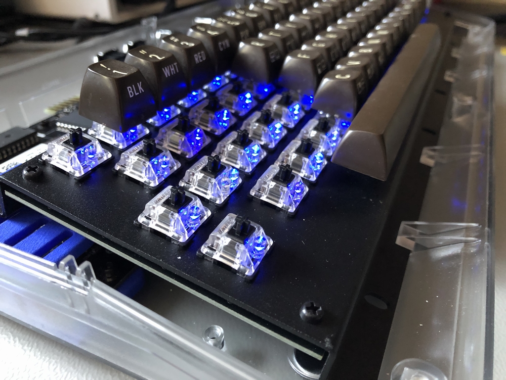
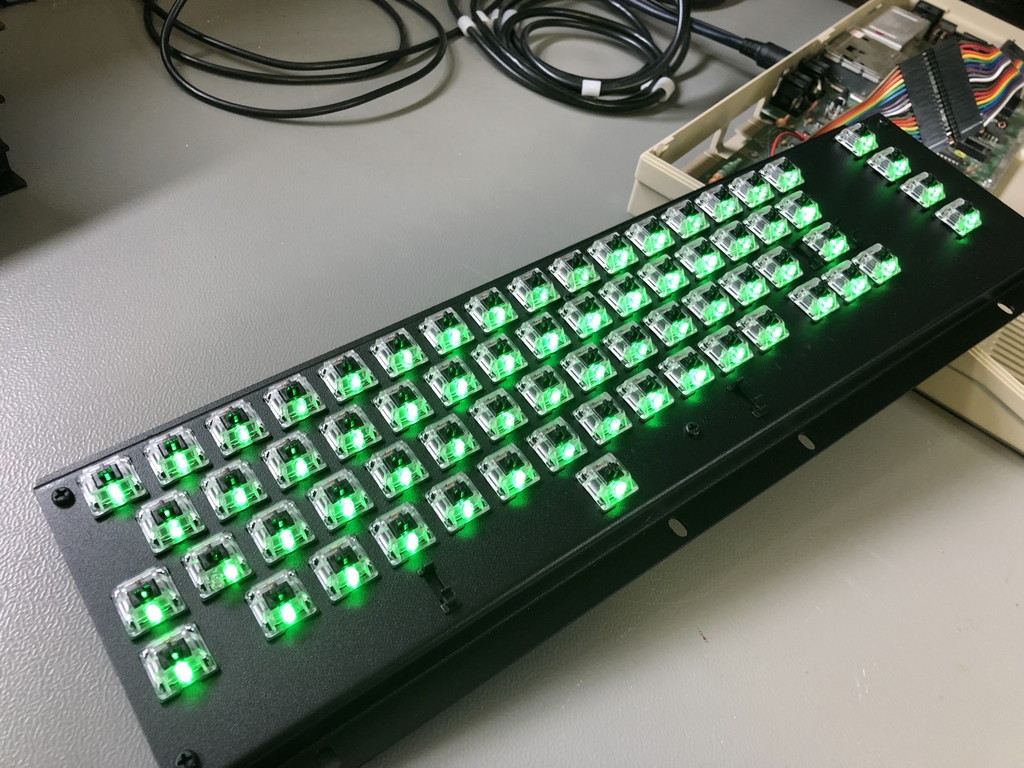
If making a MechBoard64 Light Mod Edition (link), this would be the best time to install the LEDs into each microswitch. There is no functional difference between the Light Mod Edition and the standard version of the MechBoard64 – except for the LEDs. Furthermore, the LED circuit functions seperately from the keyboard. It is therefore not neccessary to install the LEDs to make the keyboard work!
Installing LEDs into the Microswitches
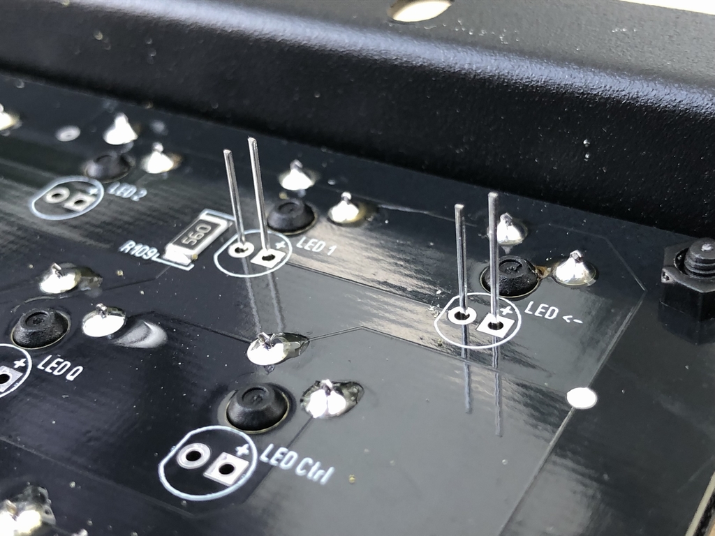
Use 3mm LEDs which can handle at least 2.0VDC (most LED colors support this). The 2.0VDC forward voltage is achieved by using 56Ω resistors. By doing so, pretty much any LED, regardless of color, can be installed without worrying too much about LED specs. This will obviously reduce the amount of dissipated light from LEDs which can handle a higher voltage. It should be noted, that if e.g. 0Ω ‘resistors’ are used instead of 56Ω resistors, the forward voltage will increase to about 2.5V and hence increase the strength of the illumination. This will only work safely if the LEDs are rated for at least 2.5VDC.
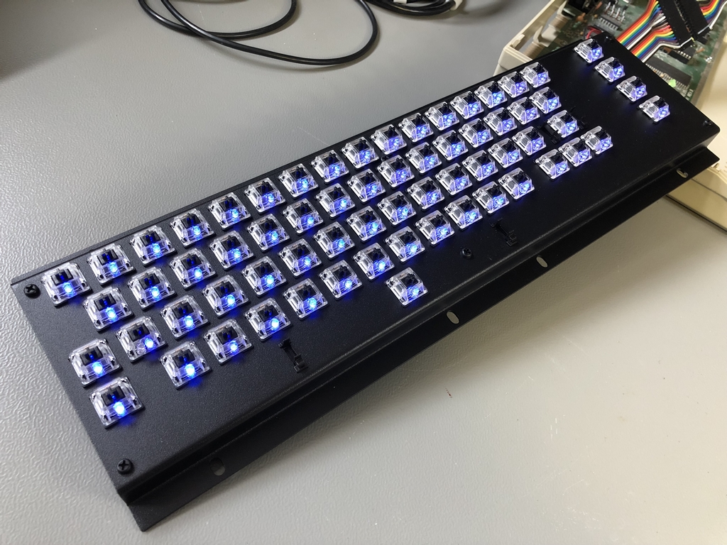
Install the anode (usually the longest legs) of each LED into the socket where it says ‘+’ on the PCB. Start by soldering in just one of each LED leg. This way it is really easy to corect those LEDs which have moved out of their sockets during the initial soldering. Finish the LED installation by cutting the excess mateial off.

Installing LEDs into the ShiftLock Microswitch
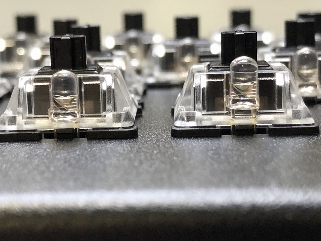
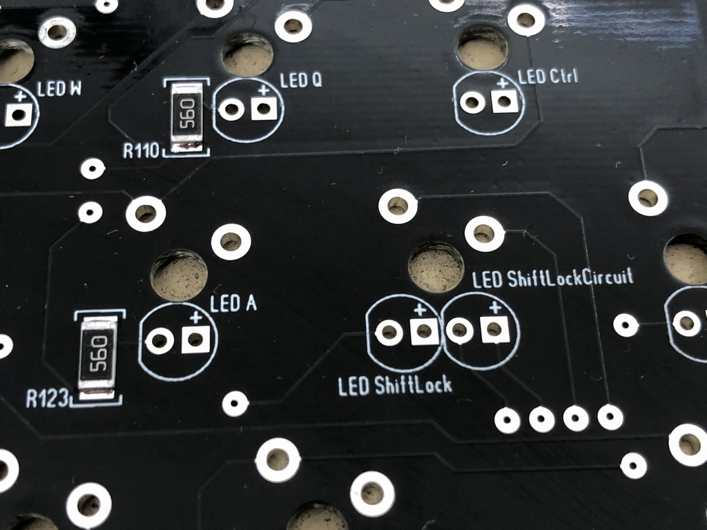
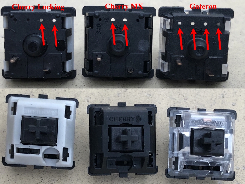
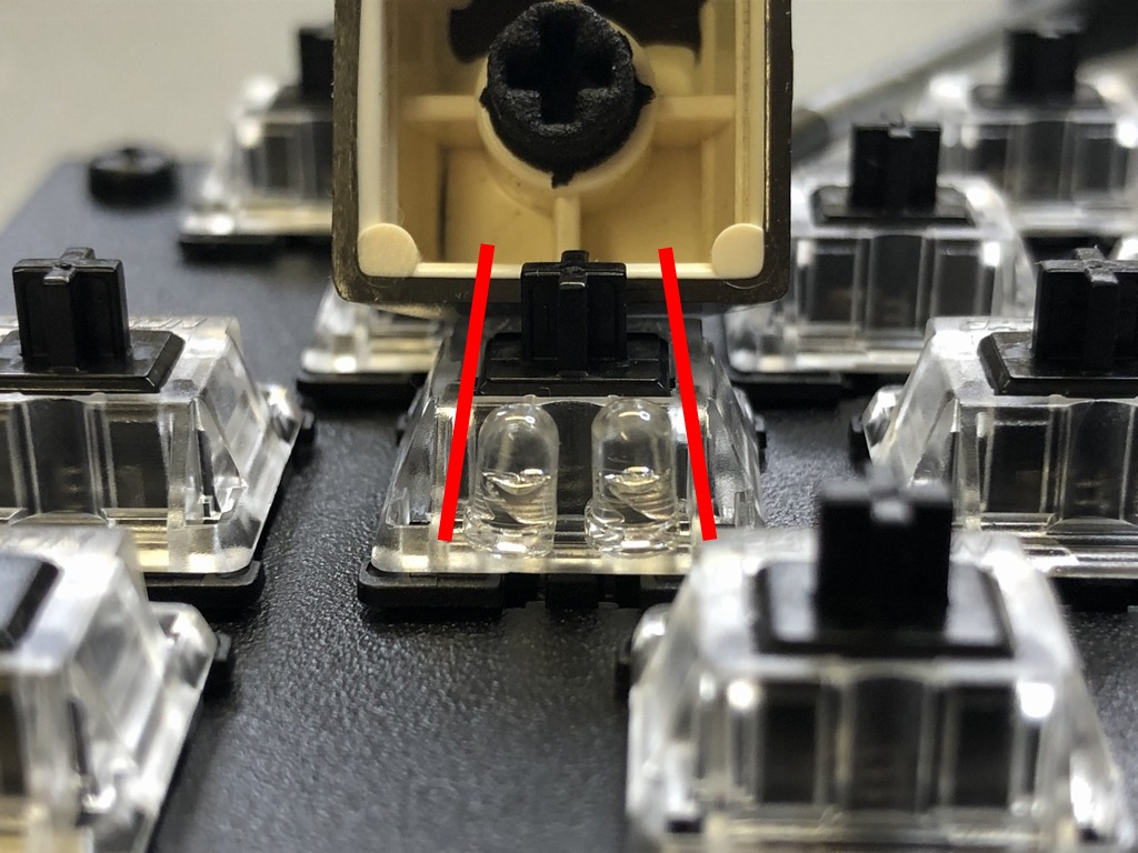
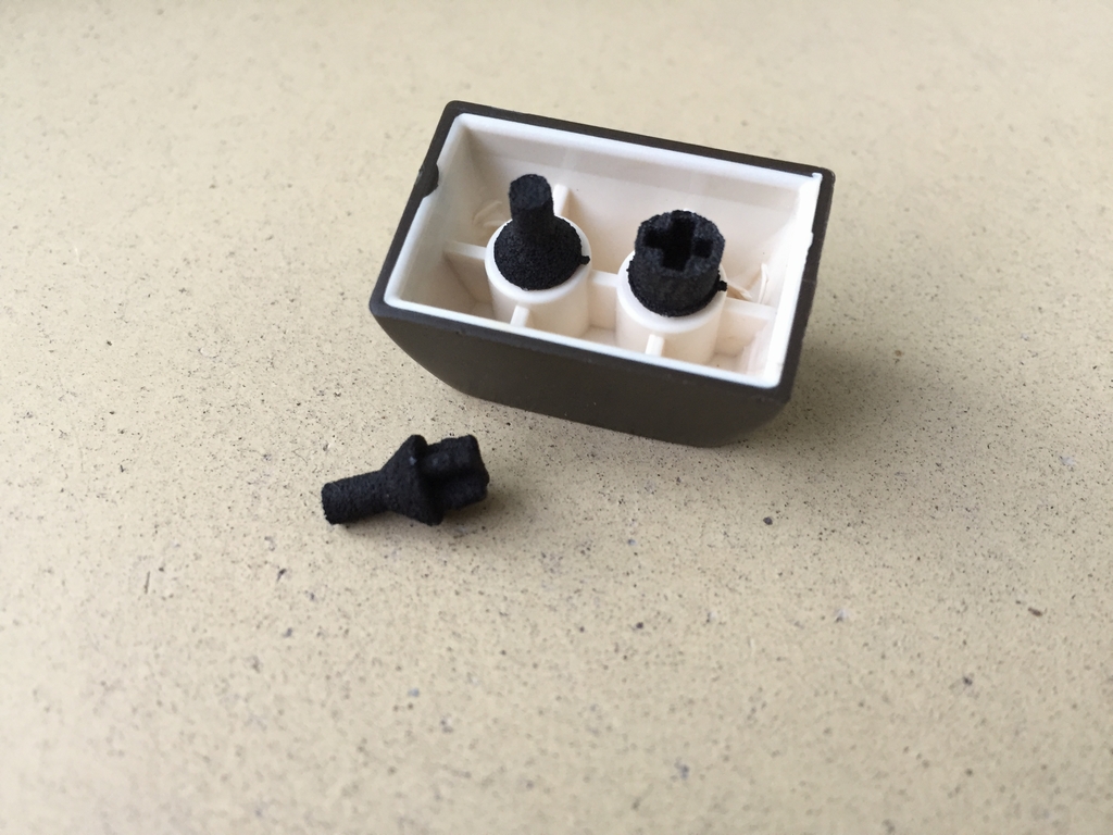
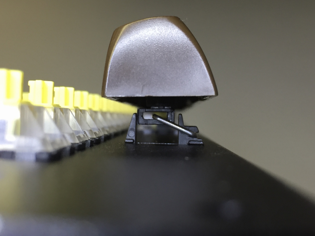
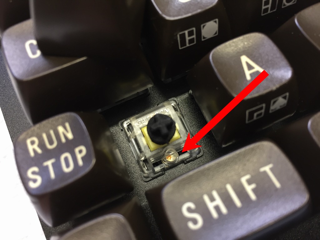
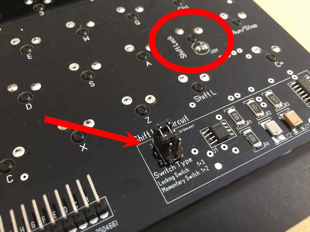
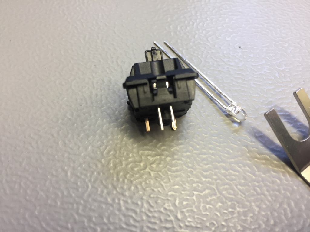
The shiftLock microswitch has two LEDs installed. The one to the right (LED ShiftLock) should be of the same color as the rest of the keyboard while the one on the left (LED ShiftLock circuit) is for the push on – push off circuit and could be whatever color is wanted. Thus, four holes are needed in the base of the microswitch for the two LEDs. In this context, Gateron microswitches already have four holes in their base for the two LEDs. Cherry mx switches does not but can probably be made manually. Fitting two LEDs underneath the SiftLock key is a really tight fit. The trick is to make them tilt slightly towards the center axis of the microswitch as shown below (red arrows). This way the ShiftLock key doesn’t get stuck unintentionally.
There is not enough room for installing SIP sockets so the LEDs should be soldered directly into the PCB.
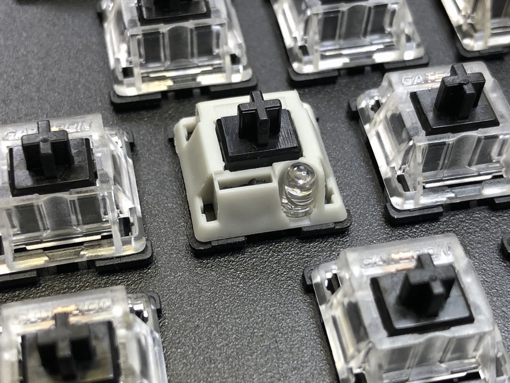
Using a Cherry Locking switch (latching switch) is also possible. Simply install the LED into the groove on the right side of the switch. This way a LED can be installed with a color like the rest of the keyboard.

Keycaps and Keyboard Stabilizers
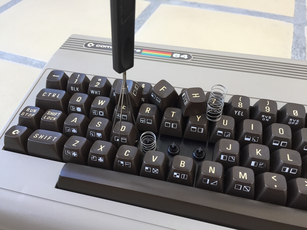
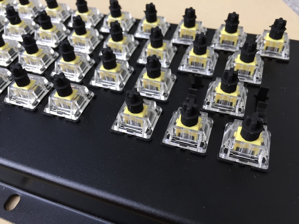
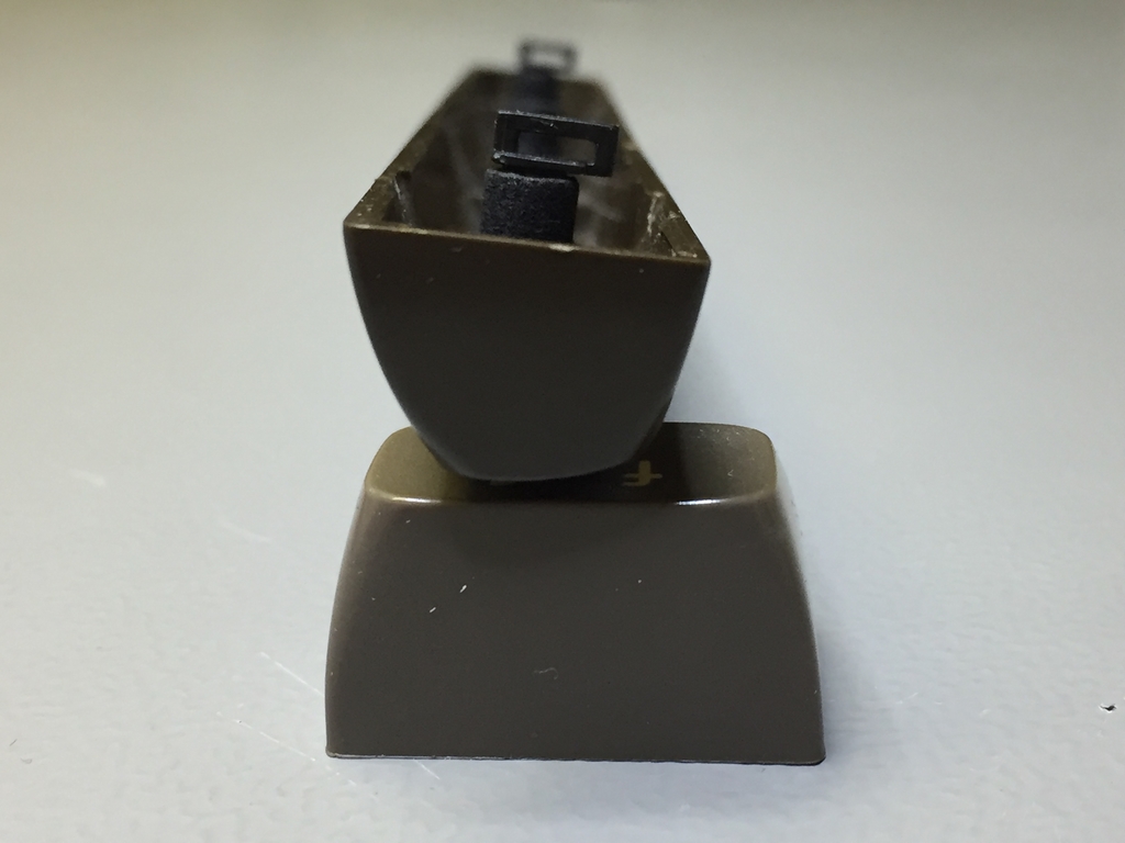
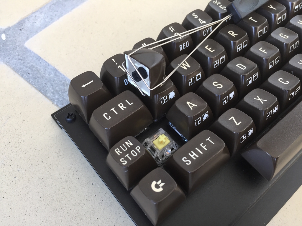
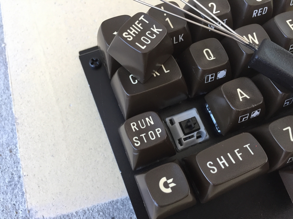
Use a keycap puller to remove the keycaps from your original Commodore 64 keyboard. These keycaps are needed to finish the installation of the MechBoard64. The easiest way to mount the 3D printed adapters is to insert them into the keycaps first. Use a hard surface (e.g. a table) and firmly press on top of the keycaps to push the 3D printed adpater to the bottom of the keycaps. Then attach the 3D printed key adapters to the stems of the microswitches using light force. All 1.5u sized keys (Shift keys, Function keys, Restore and CTRL) must have a 3D printed stem installed into the free hole to stabilize the keys during key presses.
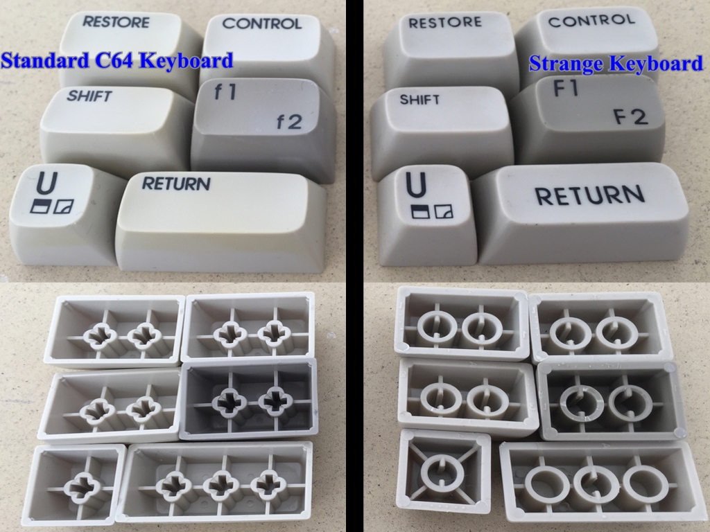
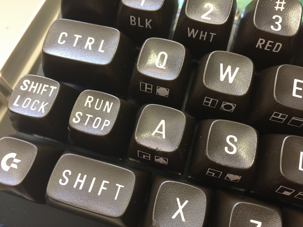
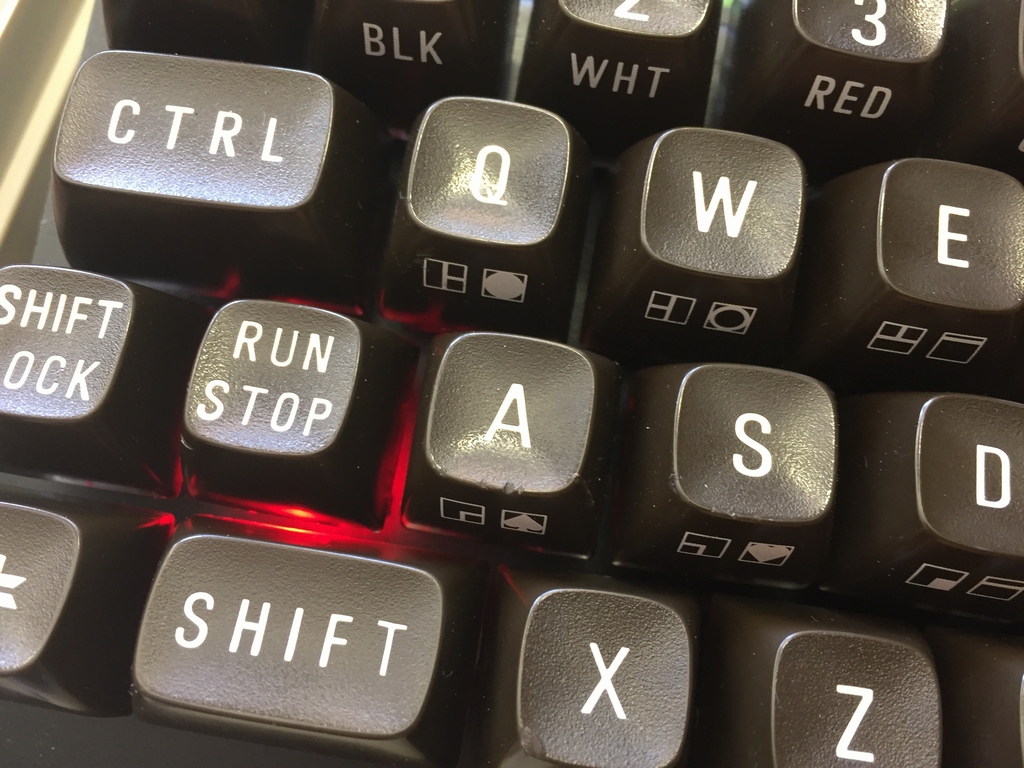
It is important to note that the 3D printed key adapters only work with Cherry mx style switches (e.g. Gateron) and the standard Commodore 64 keycaps. Other C64 keycaps, like the ‘strange’ ones shown below or keycaps from Commodore VIC20 keyboards (link), will not work and hence cannot be used with the 3D printed key adapters!
Return Key Installation
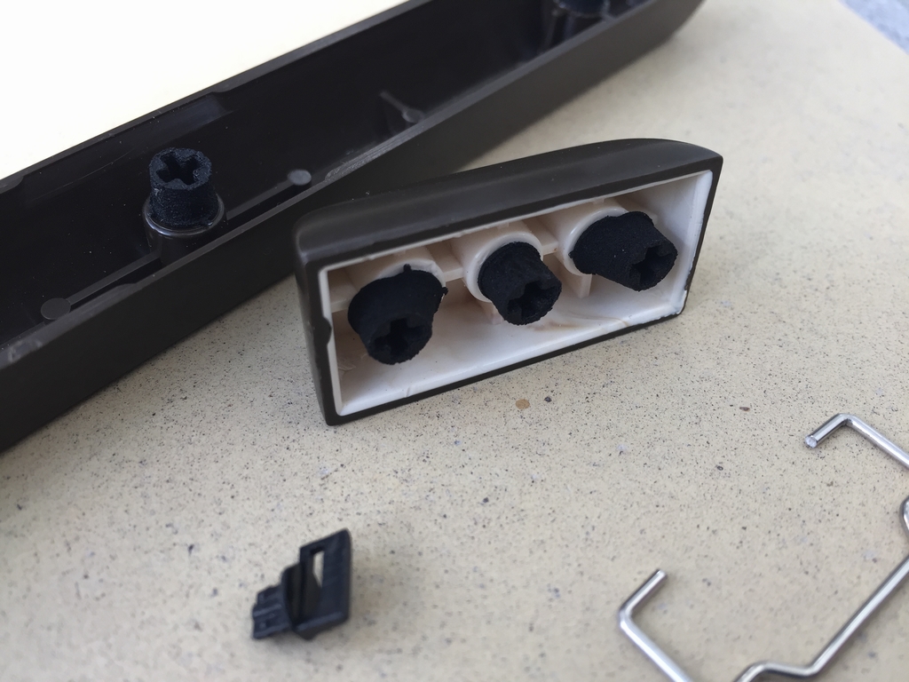
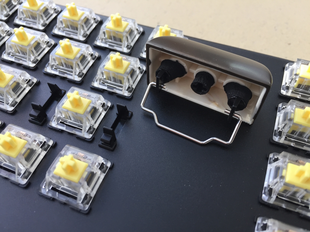
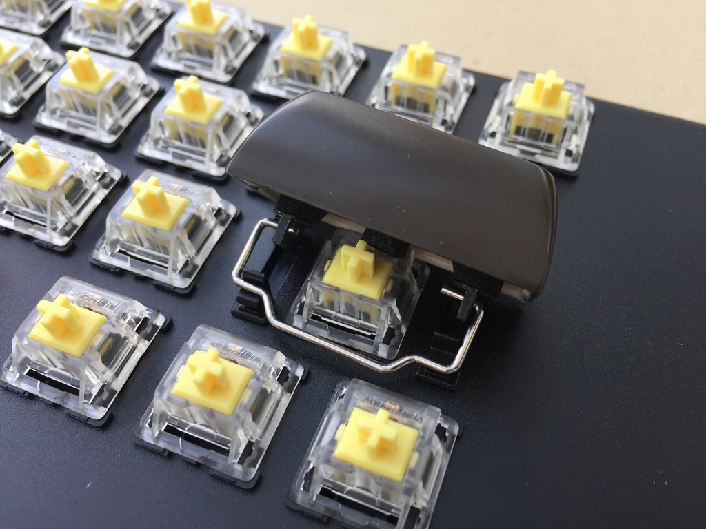
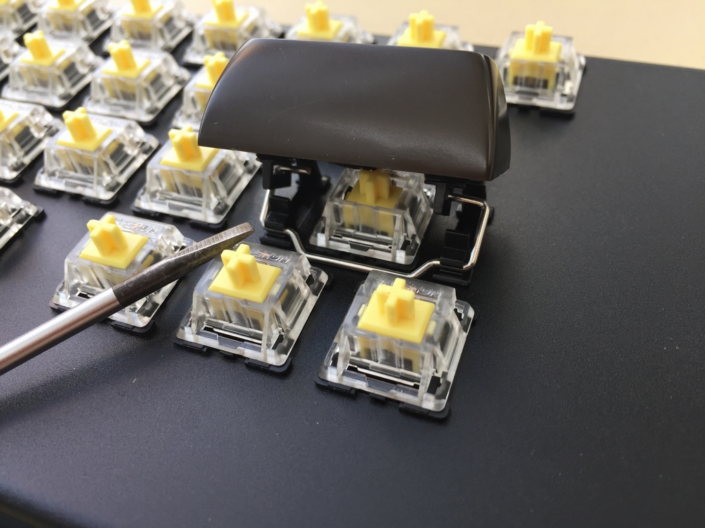
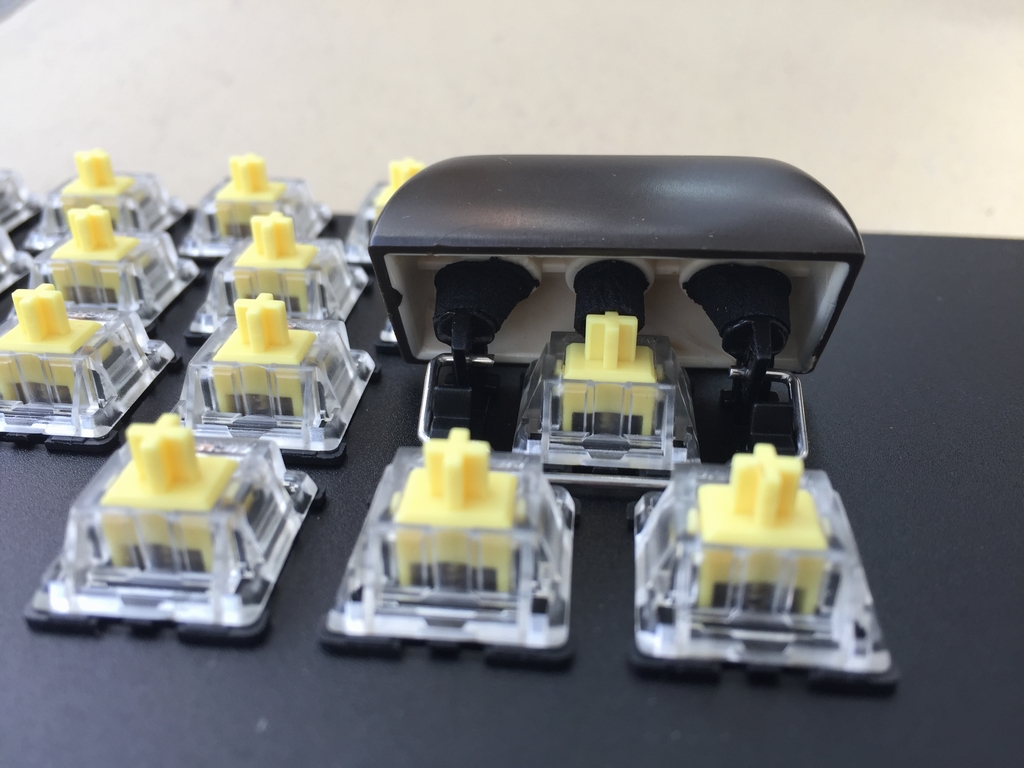
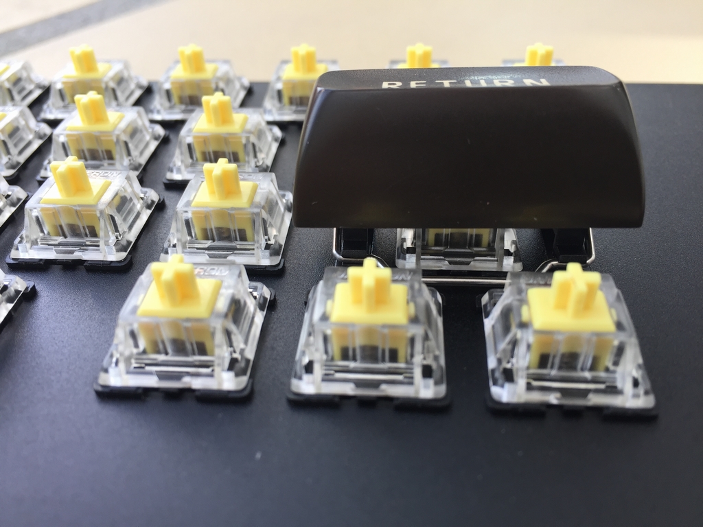
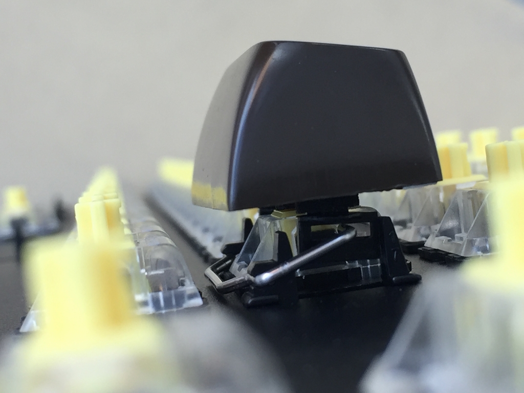
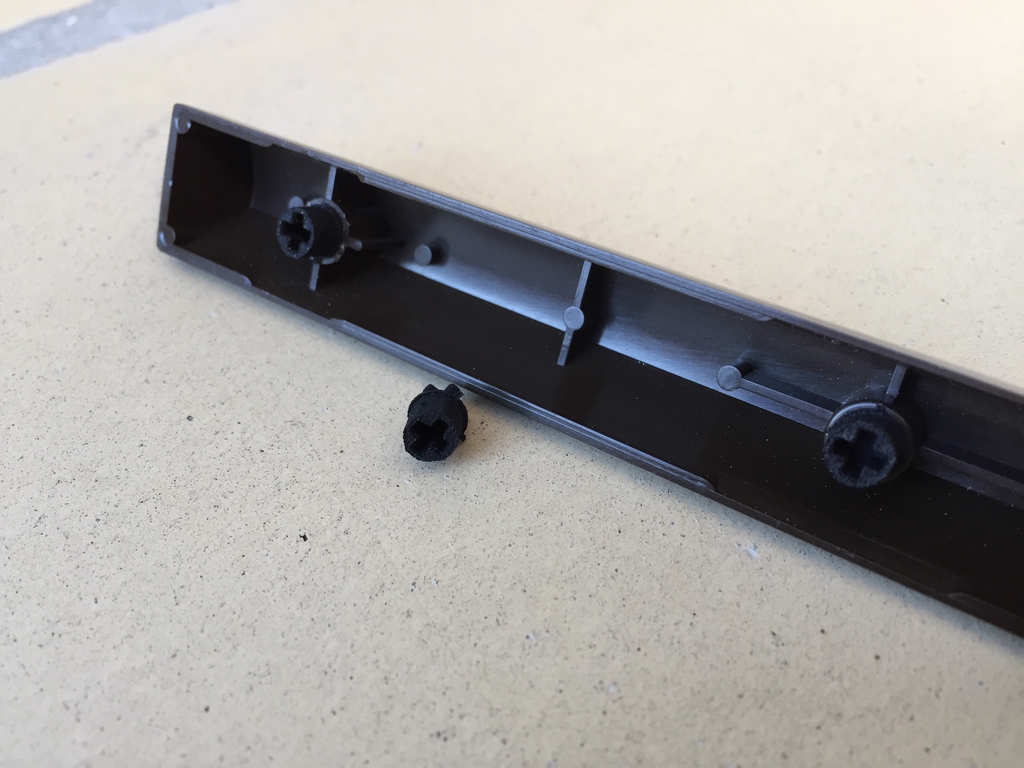
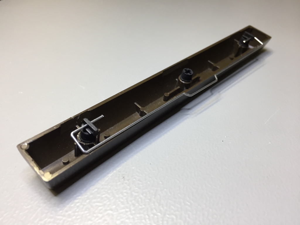
Add the 3D printed adapters for the Costar keycap inserts to the outer holes of the Return key and attach the Costar keycap inserts and stabilizer wire. The longer part of the Costar keycap inserts must point backward. The stabilizer wire has to point forward towards the front of the keyboard. Install the Return key in the keyboard. A flat headed screwdriver may be used to gently snap the stabilizer wire into the Costar plate mounted clips. Make sure the Return key goes smootly when pressed.
Spacebar Installation
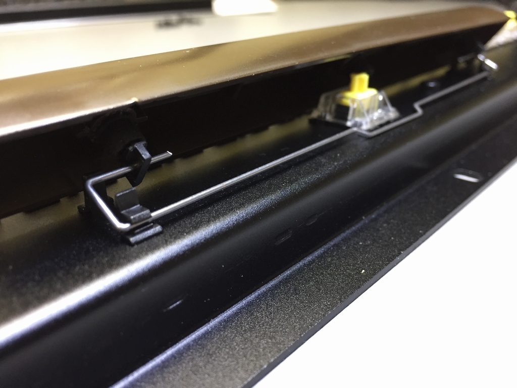
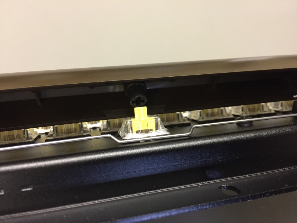
Add the 3D printed adapters for the Costar keycap inserts to the outer holes of the Space bar key and attach the Costar keycap inserts and stabilizer wire. The outer holes of the Space bar use the same 3D printed key adapters as the rest of the keys.
The longer part of the Costar keycap inserts must point backward. The stabilizer wire has to point forward towards the front of the keyboard. Install the Space bar in the keyboard. A flat headed screwdriver may be used to gently snap the stabilizer wire into the Costar plate mounted clips. The same flat headed screwdriver may be used to hold the mircoswitch stem down during the attachment of the Space bar. After installation, make sure the Space bar key goes smootly when pressed.
Keycaps Installation
Attach the remaining Commodore 64 keycaps to the top part of the 3D printed adapters to finish the keyboard.
Installing the MechBoard64 in your Commodore 64
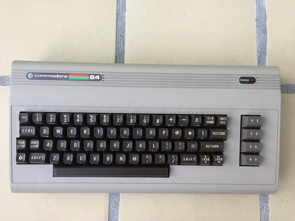
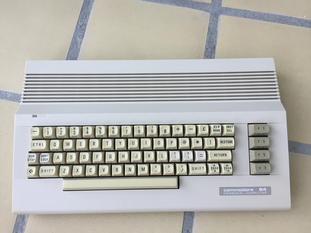
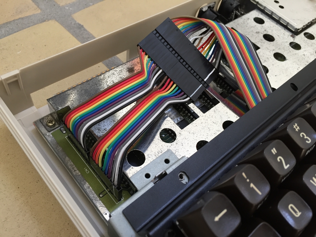
To install the MechBoard64 into a Commodore 64, the original keyboard has to be removed. The MechBoard64 has been tested in the Commodore 64 cases imaged below.
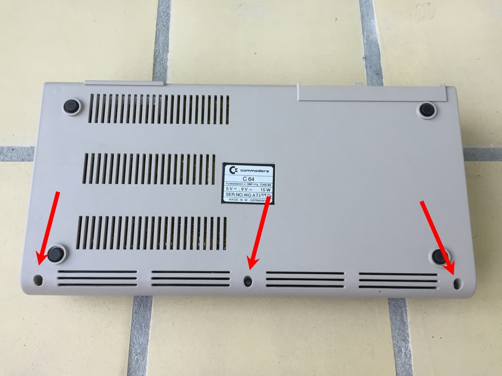
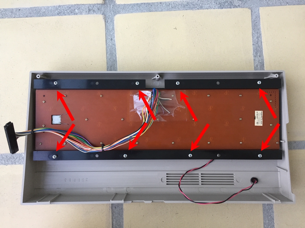
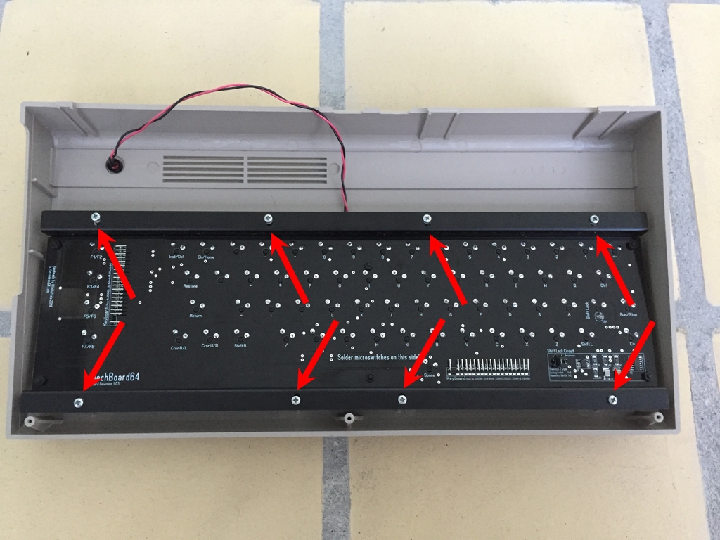
Commodore 64 Breadbox
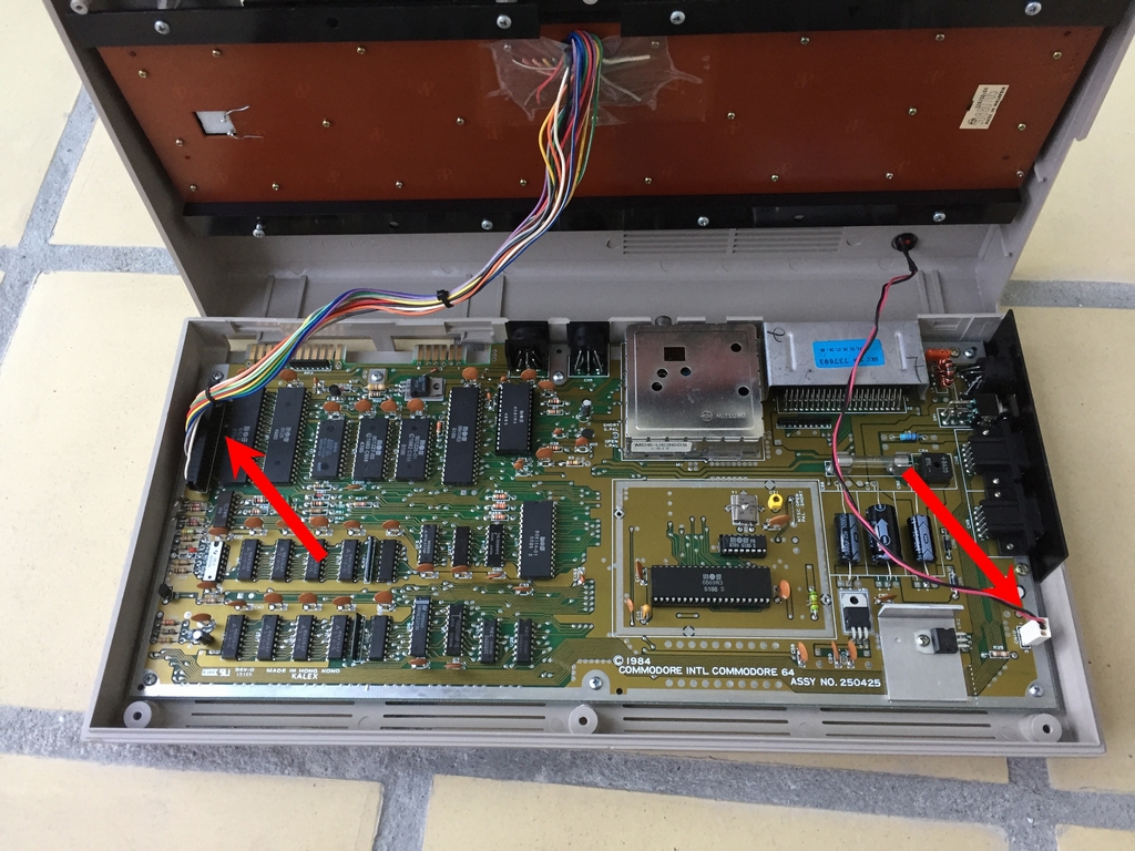
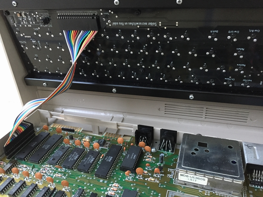
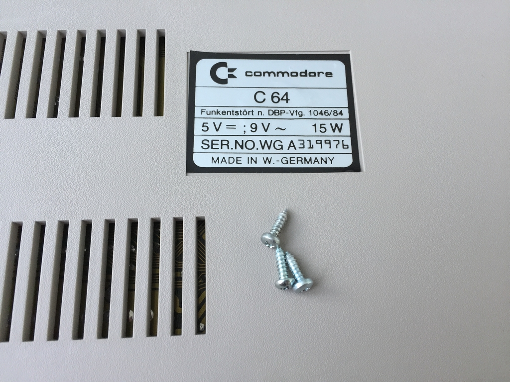
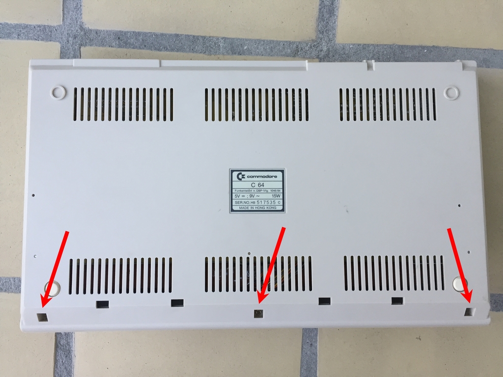
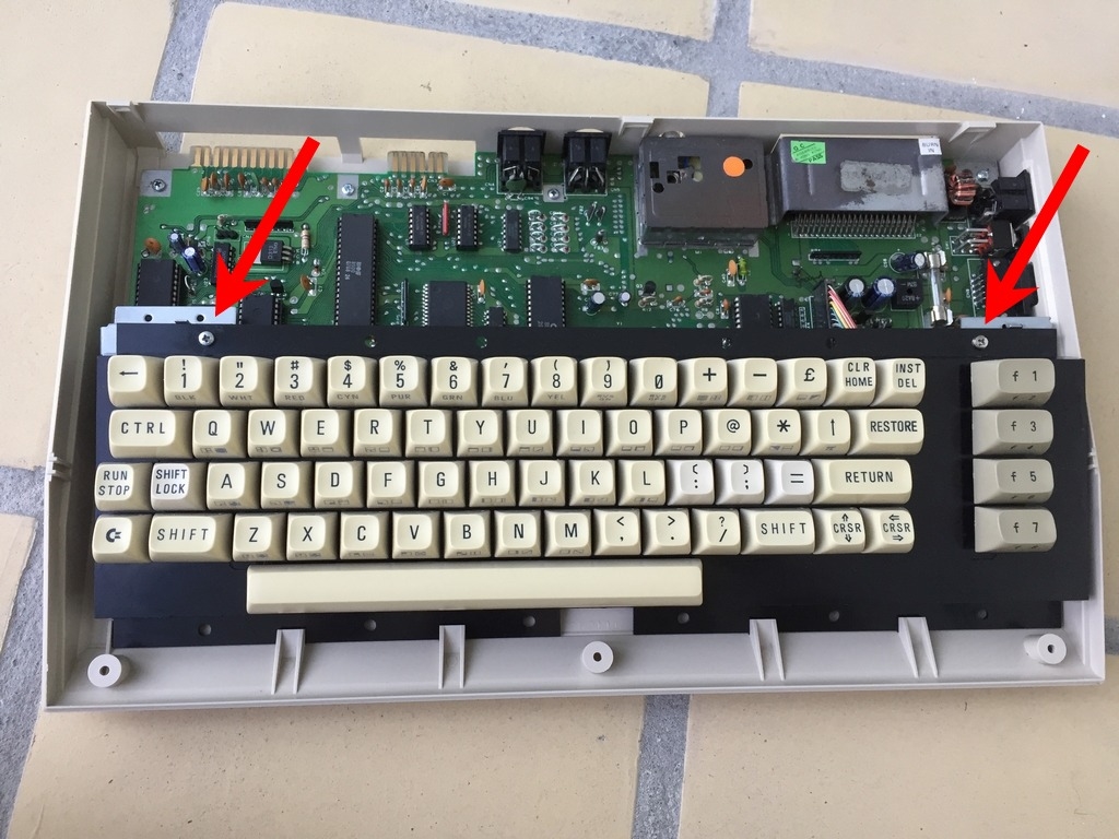
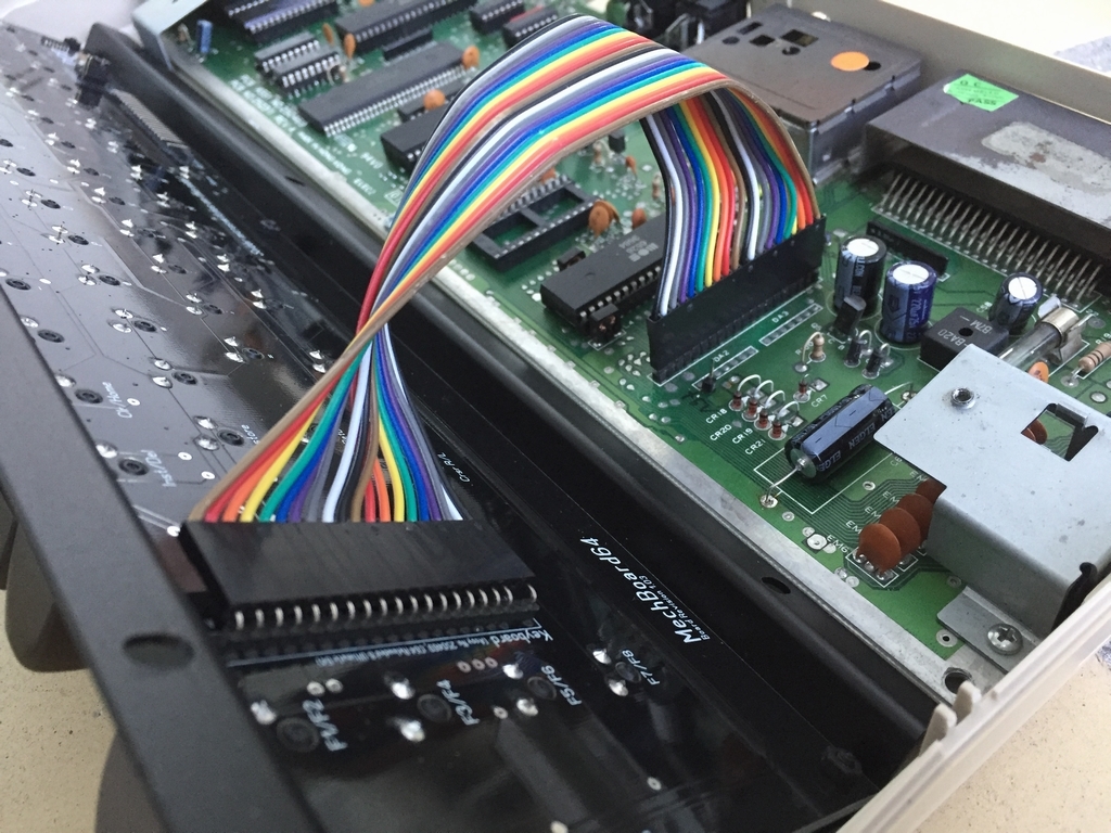
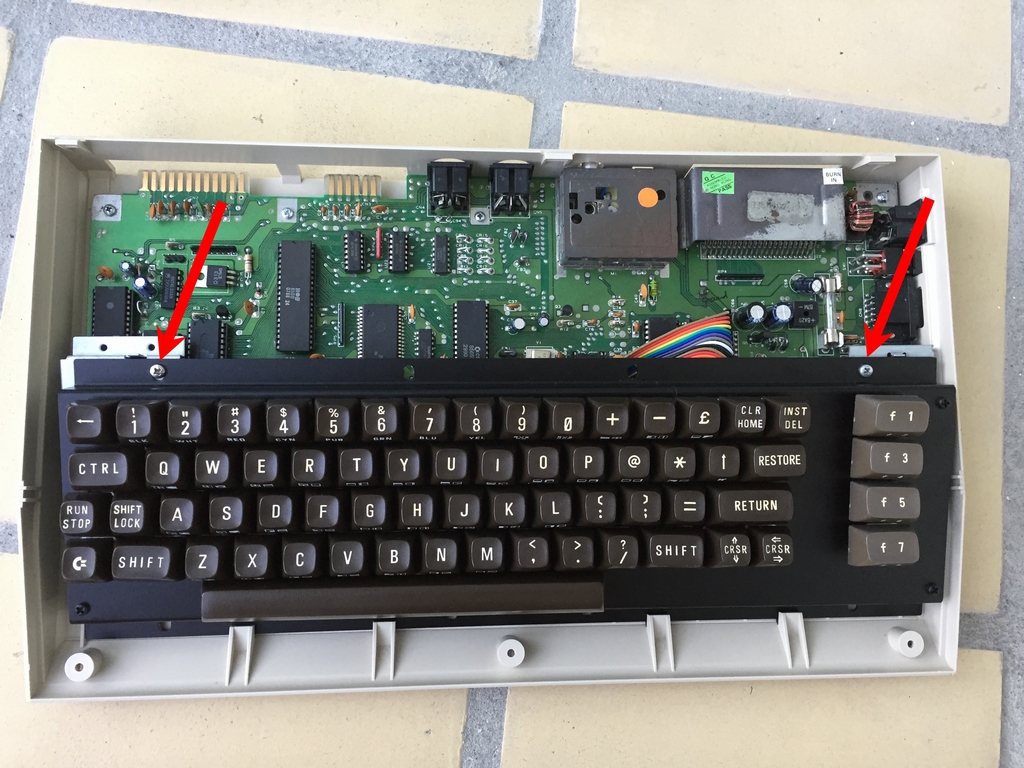
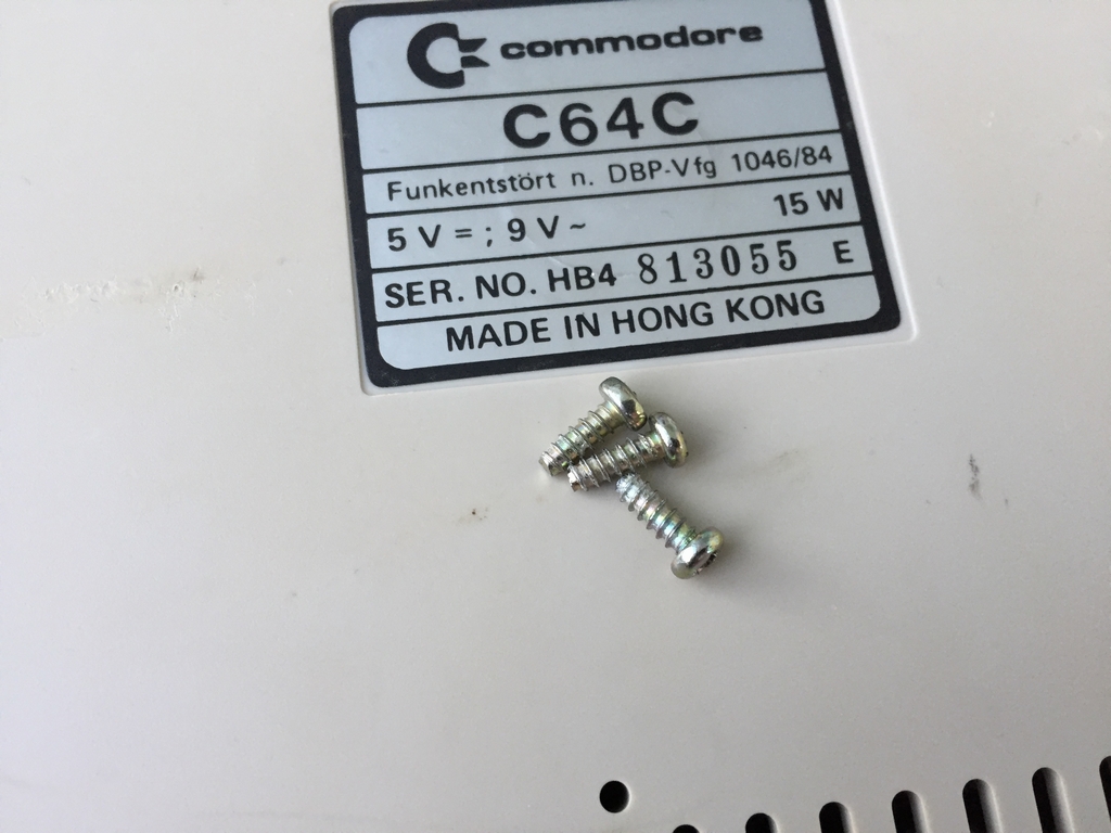
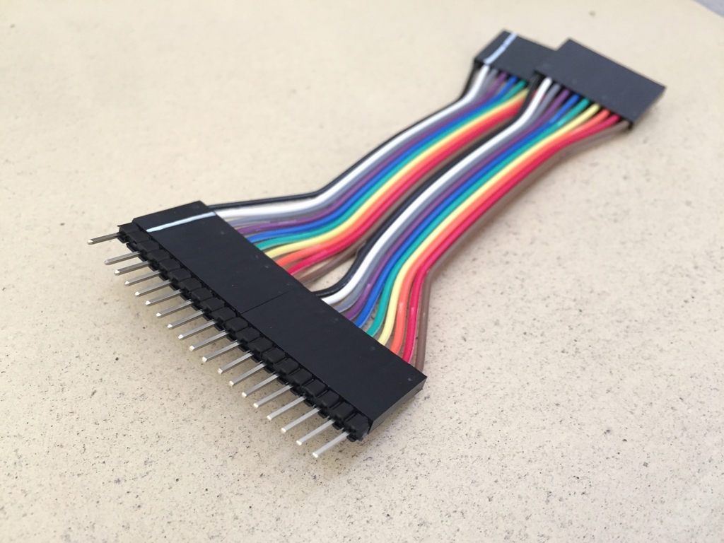
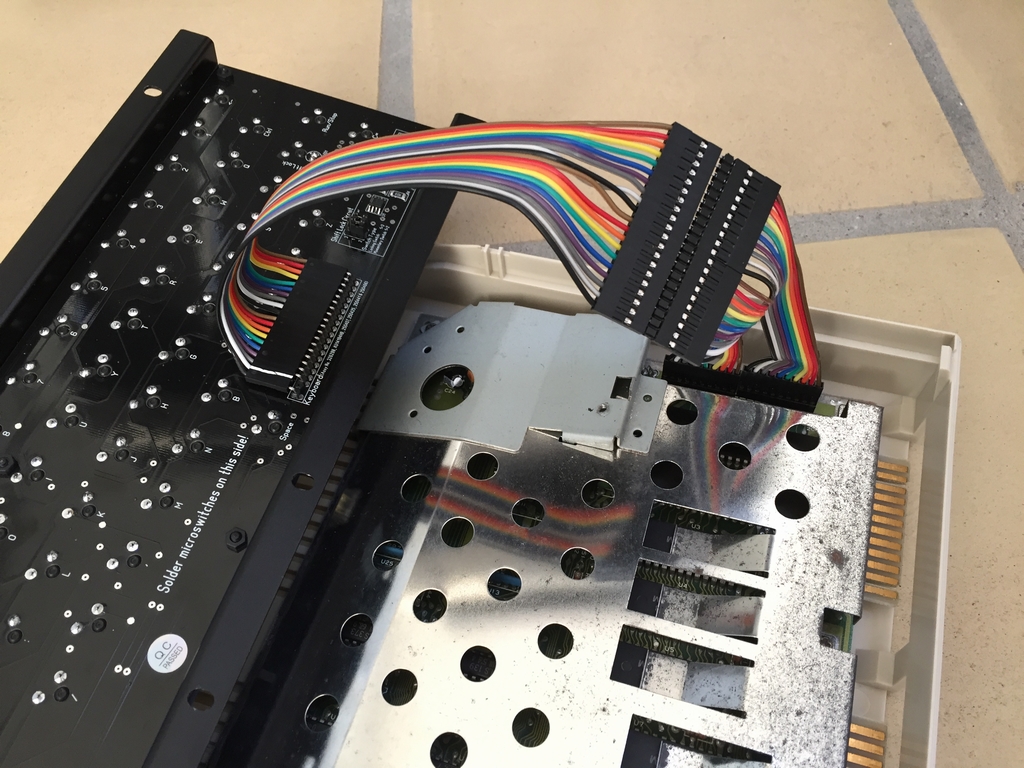
Remove the three screws on the bottom of the case. Remove the keyboard plug and power LED wire. Unscrew the old keyboard. Insert and fasten the MechBoard64 using the same screws that were just removed. Attach the ribbon cable to the MechBoard64 and Commodore 64 motherboard. Pay attention to the direction of the cable – the missing pin on the keyboard has to match the missing pin on the motherboard! Carefully reattach the top part to the bottom part of the case and fasten it using the three screws that were removed during the disassembly.
Commodore 64C slim case (including Kickstarter/Pixelwizard cases)
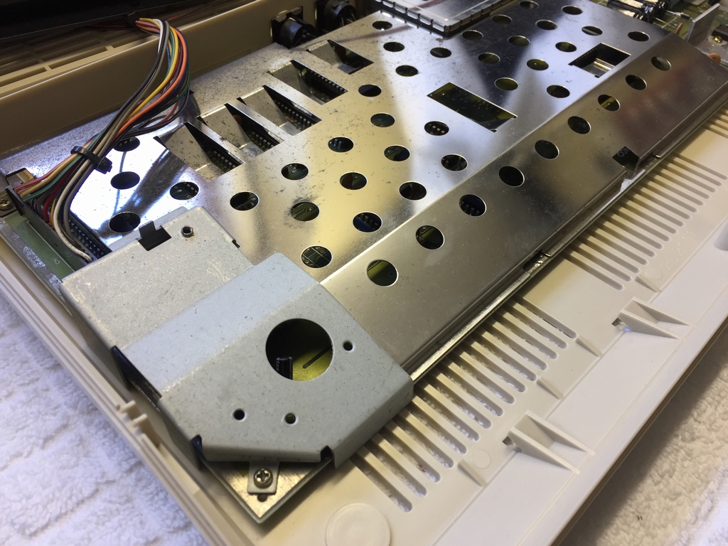
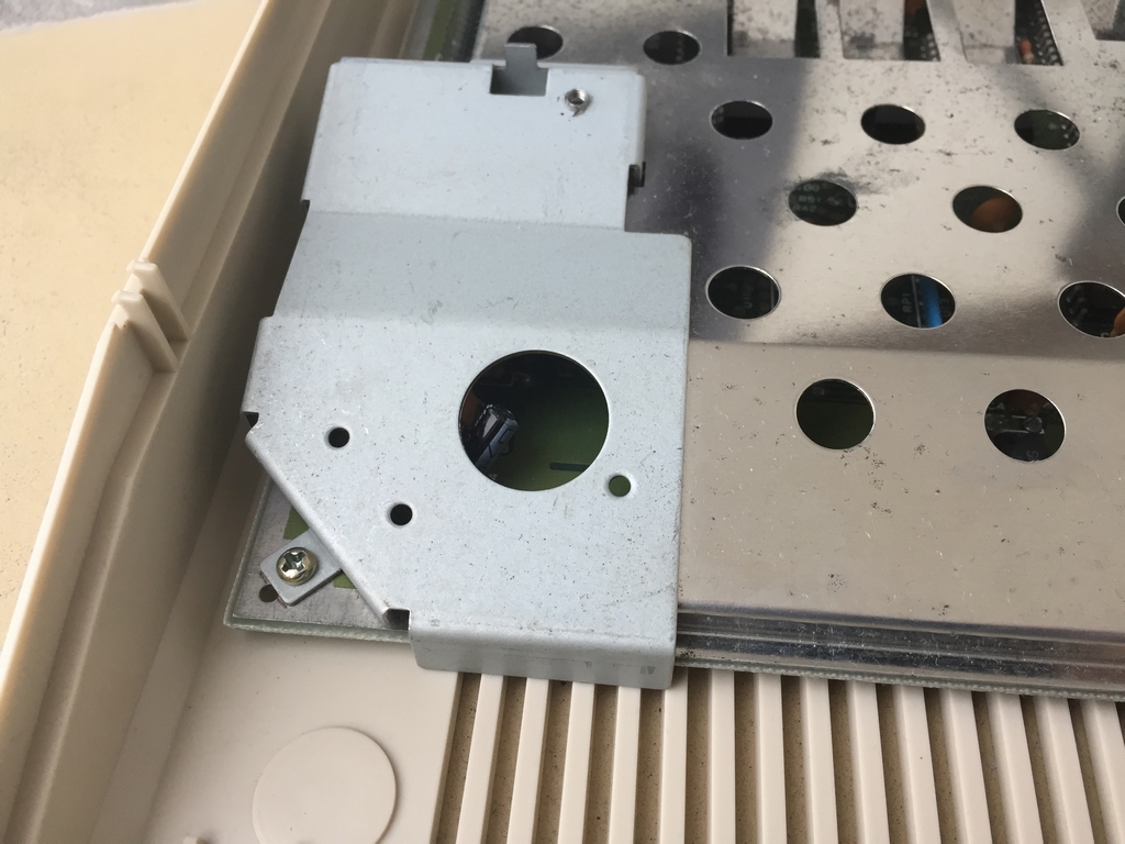
Remove the three screws on the bottom of the case. Unscrew the old keyboard. Remove the keyboard plug and power LED wire. Attach the ribbon cable to the MechBoard64 and Commodore 64 motherboard. Pay attention to the direction of the cable – the missing pin on the keyboard has to match the missing pin on the motherboard! Insert and fasten the MechBoard64. Carefully reattach the top part to the bottom part of the case and fasten it using the three screws that were removed during the disassembly.
Commodore 64C slim case with a wide motherboard
Some of the first slim case Commodore 64C machines had an old long board installed (Assy 250425 or Assy 250466). This combination of a wide motherboard and a slim case needs a 10 cm extension cable in order to work.
LED for the Shift Lock key
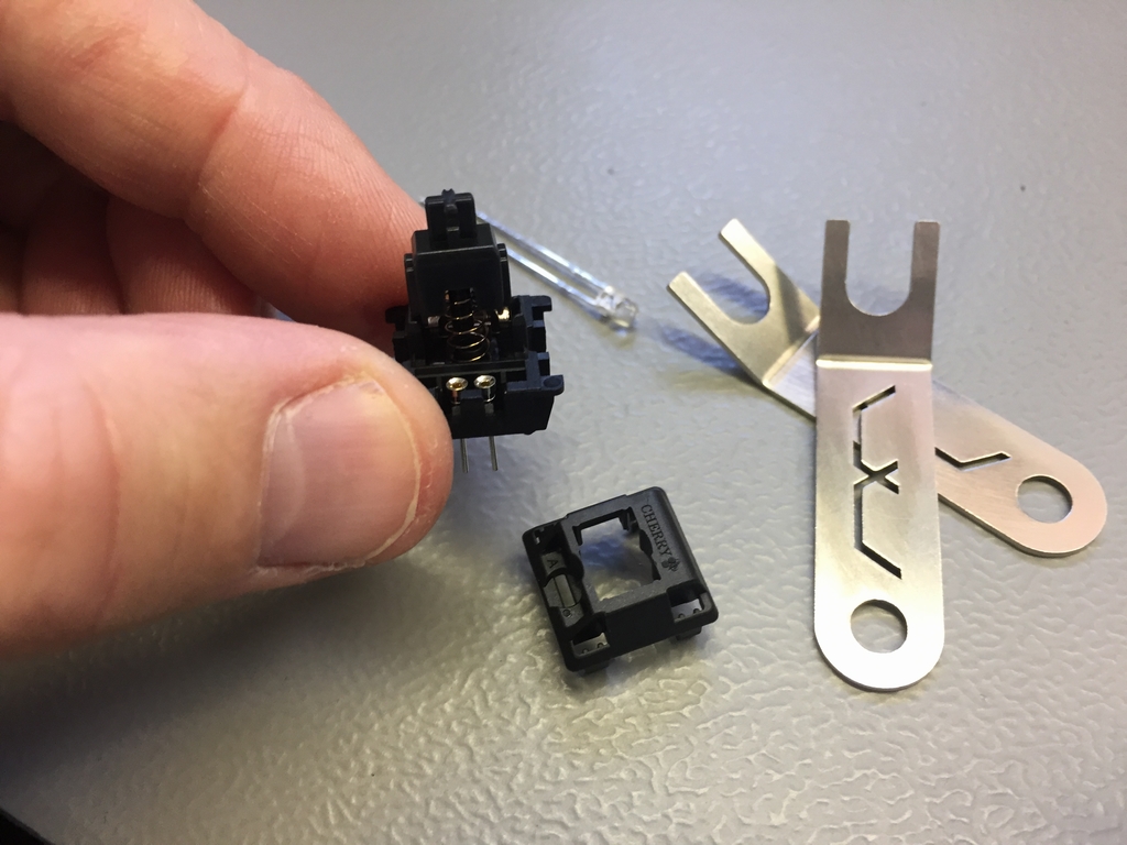
The MechBoard64 can be installed with a LED (3mm, 20mA, 1.8-2.2Vf,) for the Shift Lock circuit to indicate its current state (on or off). Before soldering the new microswitch, two SIP sockets should be installed inside the replacement switch for easy exchange of the LED.
After installation, if it doesn’t light up when activated, the LED has most likely been inserted incorrectly (i.e. the anode has been inserted into the cathode socket and vice versa). In that case, remove the Shift Lock keycap and rotate the LED to make it work.

Adding a Cherry Locking Switch for the Shift Lock
The Shift Lock key circuit uses a standard non-latching microswitch like the remainder of the keyboard. However, it can be exchanged with a latching type microswitch (e.g. a Cherry locking switch). In order to do this, the non-latching microswitch has to be de-soldered and replaced by the new latching microswitch. Locate the Shift Lock key on the backside of the PCB and desolder the LED pins and the microswitch pins. Remove the Shift Lock keycap with the keycap puller and microswitch. Insert and solder the locking type microswitch.
After the exchange, the two pin header caps inside the Shift Lock circuit area at the bottom right of the PCB has to be moved to position ‘3-1’ in order for the new switch to work.
Adding a Momentary Switch for the Shift Lock
The microswitch for the Shift Lock key can be swapped with a standard non-latching microswitch to have an LED light up under the keycap. In order to do this, the Cherry Locking switch has to be de-soldered and replaced by the new non-latching microswitch. Locate the Shift Lock key on the backside of the PCB and desolder the microswitch pins. Remove the Shift Lock keycap with the keycap puller and microswitch. Before soldering the new microswitch, two SIP sockets should be installed inside the replacement switch for easy exchange of the LED. De-attach the microswitch and insert the SIP sockets. Re-attach the top part and then insert and solder the non-latching microswitch and the two SIP sockets. Cut the LED to an appropriate length and insert it into the SIP sockets.
After the exchange, the two pin header caps inside the Shift Lock circuit area at the bottom right of the PCB have to be moved to position ‘2-1’ in order for the new switch to work. If it doesn’t light up when activated, the LED has most likely been inserted incorrectly (i.e. the anode has been inserted into the cathode socket and vice versa). In that case, remove the Shift Lock keycap and rotate the LED to make it work.
Known Issues
The MechBoard64 and a Keyrah?
Some people may want to use the keyboard with a Keyrah from Individual Computers (link) in order to connect the MechBoard64 to a modern day computer or a RaspberryPi. In those cases it should be noted that the Keyrah does not provide +5V to the pin powering the Shift Lock circuit. Therefore, neither the Shift Lock key nor the LED will function with the Keyrah. To overcome this, a locking switch can be installed instead of the non-latching standard switch. How to do this mod can be found above.
The producer of the Keyrah, Jens Schönfeld of Individual Computers, has explained why there is no +5V line connected to the Keyrah: The +5V line is not wired up on any version of Keyrah. Reason is that the USB descriptors also include a value that tells the computer how much power the device consumes. The operating system then makes a decision about leaving power on or switching it off for safety reasons. With the +5V line being “open” for any additional device, the entry in the USB descriptors would not be correct, and the USB port may get overloaded. Thus, to ensure that the device abide by the documentation so no customer can claim that the product endangers their host computer, the +5V line is “NC” on the Keyrah. However, you can wire it up to the +5V source of the USB by adding a jumper wire. Performing this mod obviously voids the warranty of the Keyrah.
The MechBoard64 and the 3D Printed Keyboard Brackets for the Ultimate64 by Pixelwizard (applies to bracket versions earlier than version 1.07)
The right 3D printed keyboard bracket by Pixelwizard (link) uses a different hole than the original Commodore 64 slim case mounts. To use the bracket you have a few options: simply do not install the screw of the right 3D printed bracket from Pixelwizard. The MechBoard64 fits the Pixelwizard case pretty tight, so it shouldn’t move around too much even if leaving out one screw. However, the lack of a securing screw will obviously make it easier for the keyboard to shift around inside the case during normal typing. The left screw can be tightened more to minimize this but this may damage the mount (now you have been warned!). You can also drill a hole into the aluminum bracket of the MechBoard64.
The design of the right 3D printed keyboard bracket by Pixelwizard also causes issues in regard to reaching the male plug on the MechBoard64. A work-around is to separate all individual leads of the ribbon cable to make it pass on the inside of the bracket.
Last option is to get a 3D printed keyboard brackets from COREi64 in Canada (link). These will work with the Pixelwizard case and the Ultimate64 without the need to modify anything (metal bracket and/or the ribbon cable).
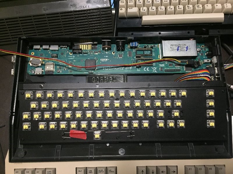
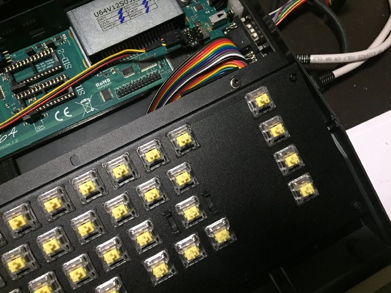
The MechBoard64 and the Ultimate64 Plexilaser Case
The MechBoard64 is not directly compatible with the sweet looking Plexilaser case (link) that is specifically made for the Ultimate64 (link) motherboard:
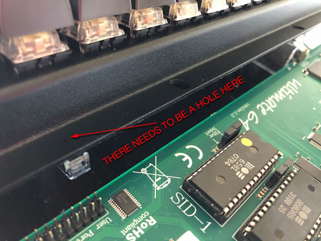
The Plexilaser case for the Ultimate64 uses a hole for securing/supporting the rear part of the keyboard. The placement of the hole is not used by the orignal Commodore 64 cases and is therefore not present in the MechBoard64. The issues can be fixed by drilling the missing holes to the aluminum bracket.
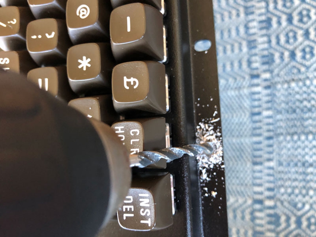
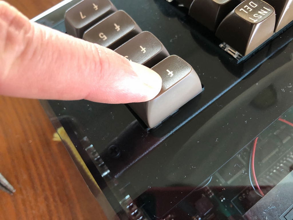
The slotted holes at the top and bottom part of the MechBoard64 bracket does not allow enough wiggle room to fit perfectly inside the Plexilaser case. This causes the case to get ‘stuck’ underneath the F1/F2 key, making it impossible to activate. Fixing the issue would require the slotted holes to be enlarged with e.g. a drill.
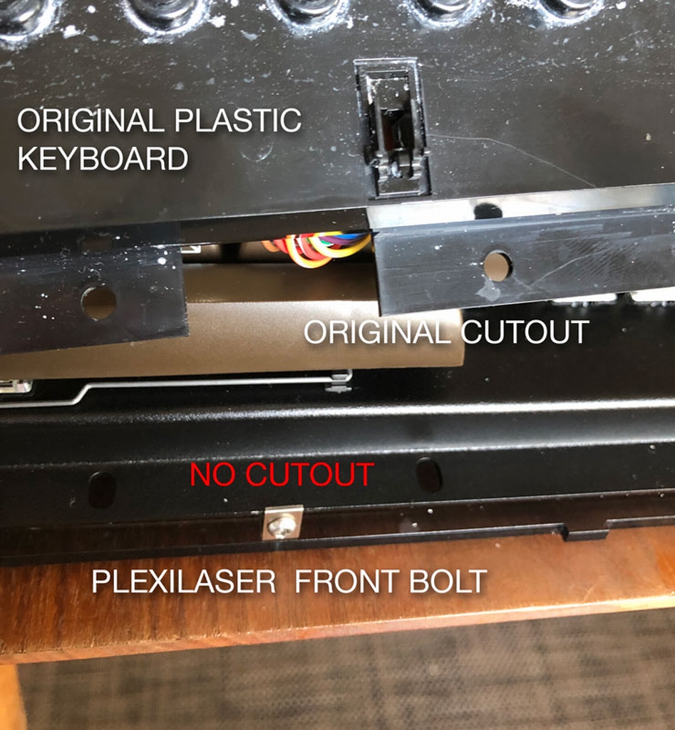
The top part of the Plexilaser case has a mounting bracket that screws right into the front of the case (just below the spacebar). This goes well with the original C64 keyboard as it has a cut out. The MechBoard64 bracket version 1.07+ now has these holes added while earlier versions need to be modifed with e.g. a Dremel or similar tool.
Manual Information
Online version 1.05
Alternative Manual
German instructions can be found here (link). Thanks Bulli_ from Forum64.de.
© breadbox64.com 2021
Hi, awesome project, I found it on PCBway shared project and I wish to build a couple. However I haven’t the original C= keycaps, can I use standard keycap instead? I will label them with the C= symbols later
Hi there, You cannot use standard keycaps 🙁 A detailed description can be found here (link).