
I’ve been racking my brain for quite some time, to find a solution on what to do with my MechBoard64 (link) keyboard project… The project started as I needed two new keyboards for my C64 Reloaded boards (link, link). Going into such a large project was quite naive, as I had absolutely no idea how much effort I actually had to put into it to get my two keyboards. However, I truly enjoyed the engineering part of creating the keyboard PCB, the search for a solution for the Shift Lock circuit, the drawing of the keyboard bracket, sending the drawings off to China and finally see it all come together. I’ve never drawn a PCB before, so that took me quite some time to learn. The laser cutting companies all ask for Adobe Illustrator files for their machines. However, I have never used that software either so that also took me a while to be acquainted with. Truth is (and don’t tell anyone, ok?), I’ve never actually owned a mechanical keyboard, so I’ve also spent a bit of time trying to understand the differences between switches, brands and where to get a hold of them.
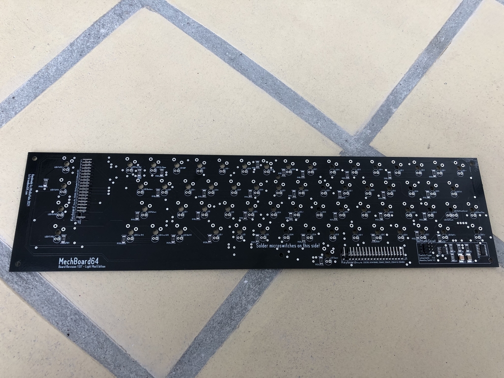
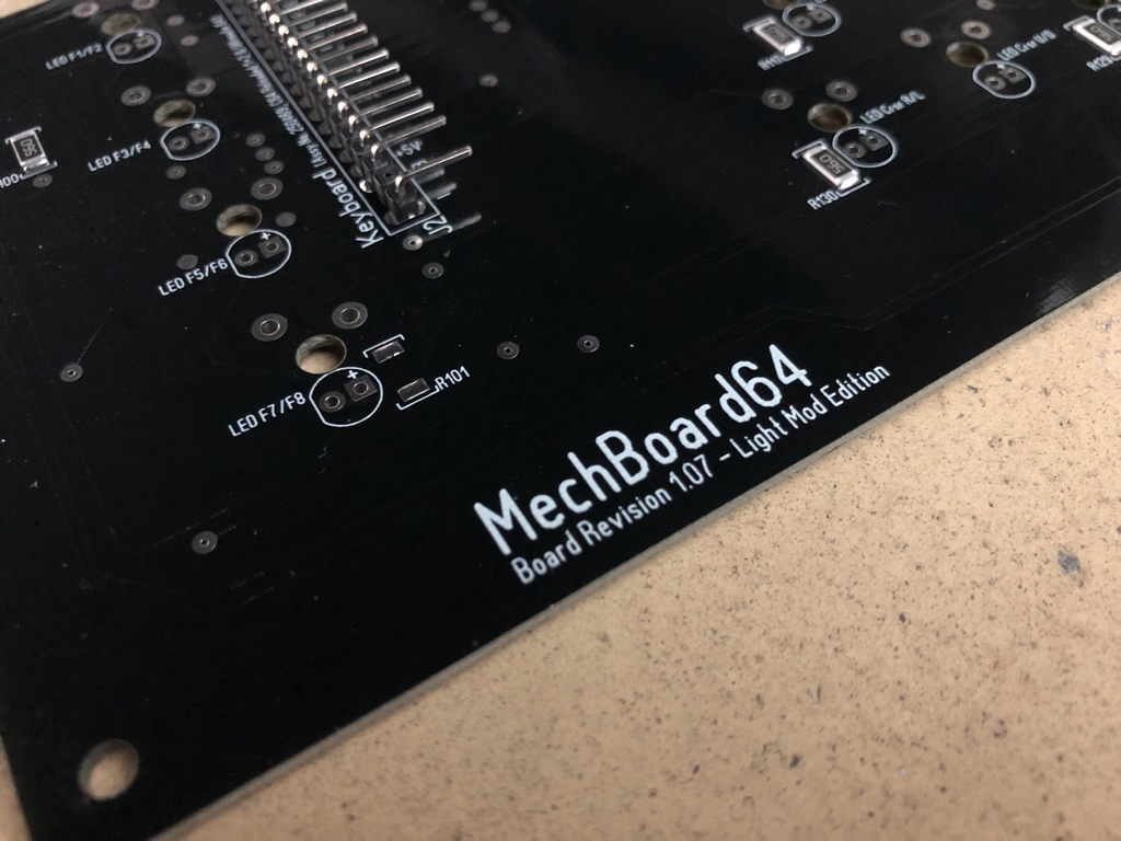
UPDATE: An illuminated version of the MechBoard64 (Light Mod Edition) is also available. There is no functional difference between the Light Mod Edition and the standard version of the MechBoard64 – except for the LEDs. Furthermore, the LED circuit functions seperately from the keyboard. It is therefore not neccessary to install the LEDs to make the keyboard work! More info here (link).
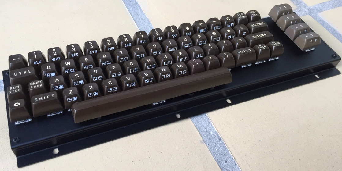
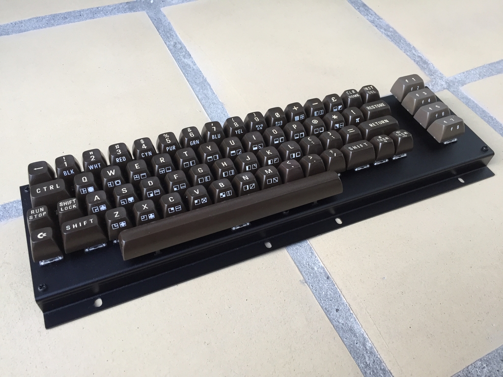
When the MechBoard64 was finally realized and presented on my blog, it soon came clear that a new mechanical keyboard was the missing piece in the creation of a brand new Commodore 64 (…well that and some new keycaps…). As I have no intention to become a Commodore 64 mechanical keyboard manufacturer, I’ve therefore decided to release all information regarding the creation of the MechBoard64 . This includes files for creating the keyboard PCB (Gerber, Excellon, BOM), the keyboard bracket (Illustrator, PDF, bend allowance drawing), 3D printed keycap adapters (.STL), the keyboard stabilizers (dimensions, material) and all miscellaneous parts (cables, screws, nuts, super lube). This way users can make their own keyboards, modify them to accommodate modern day keycaps, make groupbuys or start making batches for everyone to enjoy 🙂
Below you will find everything needed to make your own MechBoard64.
Copyright Notice
Copyright (c) 2021 MtnBuffalo, breadbox64.com
Permission is hereby granted, free of charge, to any person obtaining a copy of this software and associated documentation files (the “Software”), to deal in the Software without restriction, including without limitation the rights to use, copy, modify, merge, publish, distribute, sublicense, and/or sell copies of the Software, and to permit persons to whom the Software is furnished to do so, subject to the following conditions: The above copyright notice and this permission notice shall be included in all copies or substantial portions of the Software.
THE SOFTWARE IS PROVIDED “AS IS”, WITHOUT WARRANTY OF ANY KIND, EXPRESS OR IMPLIED, INCLUDING BUT NOT LIMITED TO THE WARRANTIES OF MERCHANTABILITY, FITNESS FOR A PARTICULAR PURPOSE AND NONINFRINGEMENT. IN NO EVENT SHALL THE AUTHORS OR COPYRIGHT HOLDERS BE LIABLE FOR ANY CLAIM, DAMAGES OR OTHER LIABILITY, WHETHER IN AN ACTION OF CONTRACT, TORT OR OTHERWISE, ARISING FROM, OUT OF OR IN CONNECTION WITH THE SOFTWARE OR THE USE OR OTHER DEALINGS IN THE SOFTWARE.
Files Download
Here is the complete .zip archive containing all the files needed for making a MechBoard64 keyboard. The files can be downloaded using this link:
MechBoard64 version 1.07 + Light Mod Edition
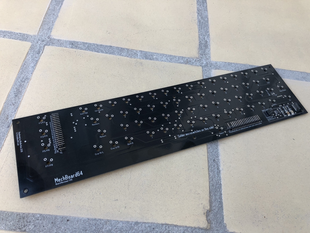
Printed Circuit Boards
The standard printed circuit board can be ordered from PCBway.com using this direct link (a new tab/window will open).
UPDATE: The Light Mod Edition printed circuit board with optional LEDs underneath each keycap can also be ordered from PCBway.com using this direct link (a new tab/window will open). More info on that particular MechBoard64 can be found here (link).
Keyboard Bracket
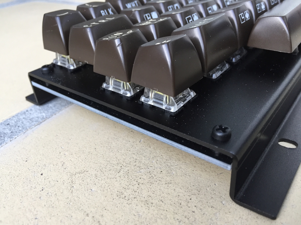
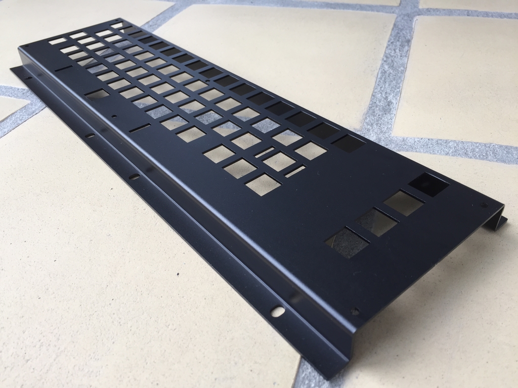
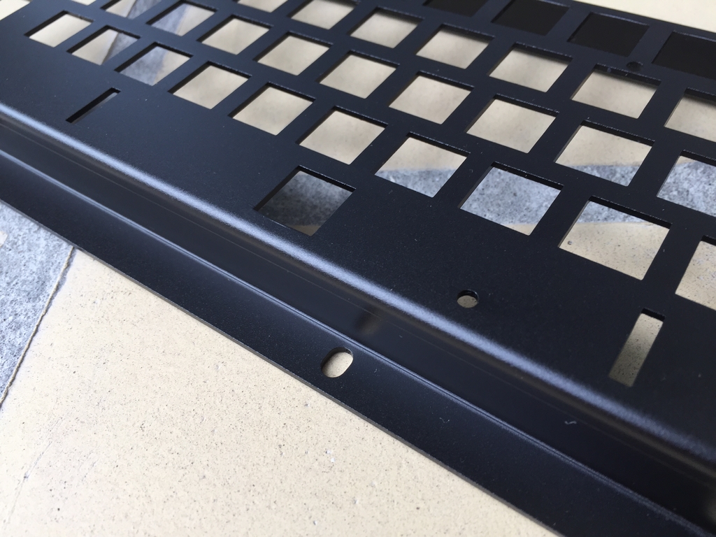
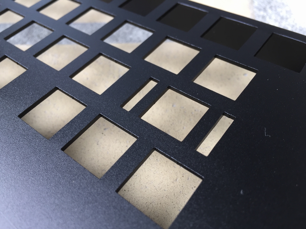
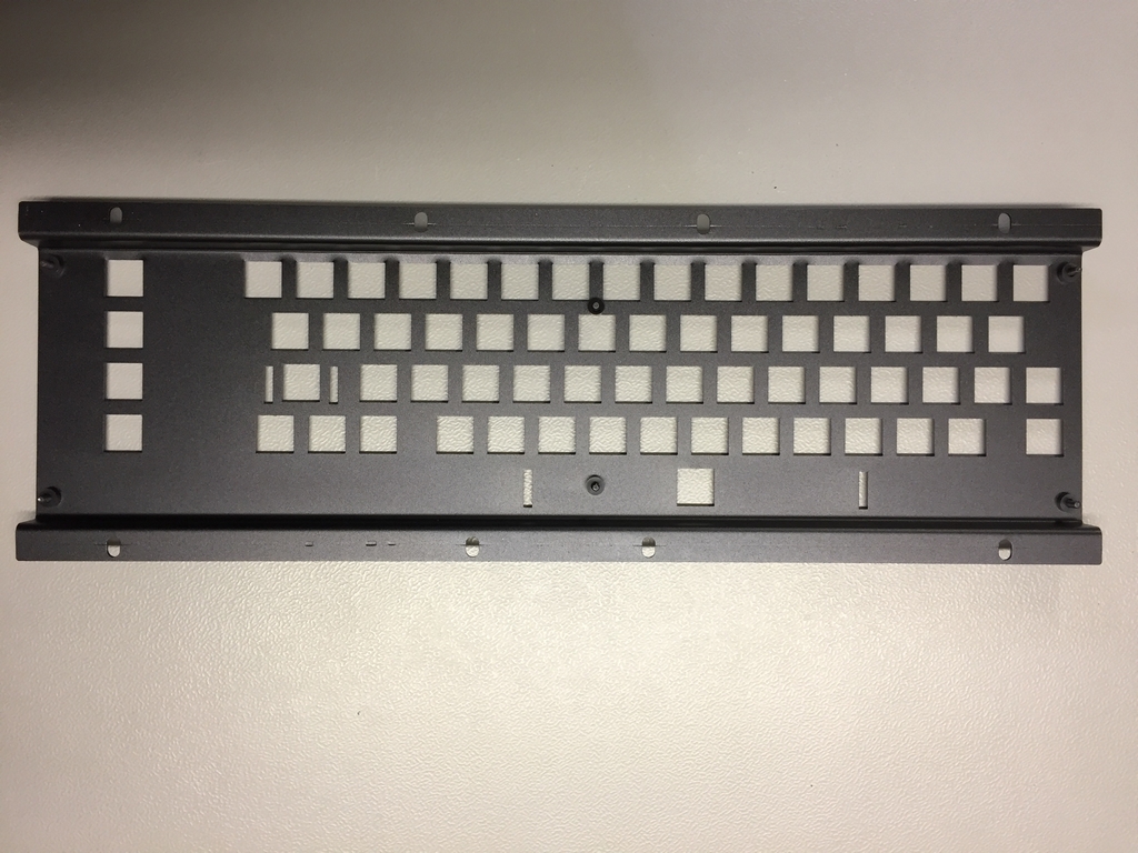
The keyboard bracket should be made in 1.5mm aluminum to fit the microswitches. The bracket can be plain, anodized or powder coated. Powder coating is stronger than just anodizing the surface. I used a company in China called Shanghai Yinuo Machinery Co., Ltd. Their webside can be found here (link). They powder coated my brackets with great results. Their email is this (email).
UPDATE #1: In the comments section below is information on a US based company that can also produce the brackets (thanks Stefan!).
UPDATE #2: The bracket drawing has also been updated with two more slotted holes on the top rail for better compatibility with the various third party keyboard brackets available online.
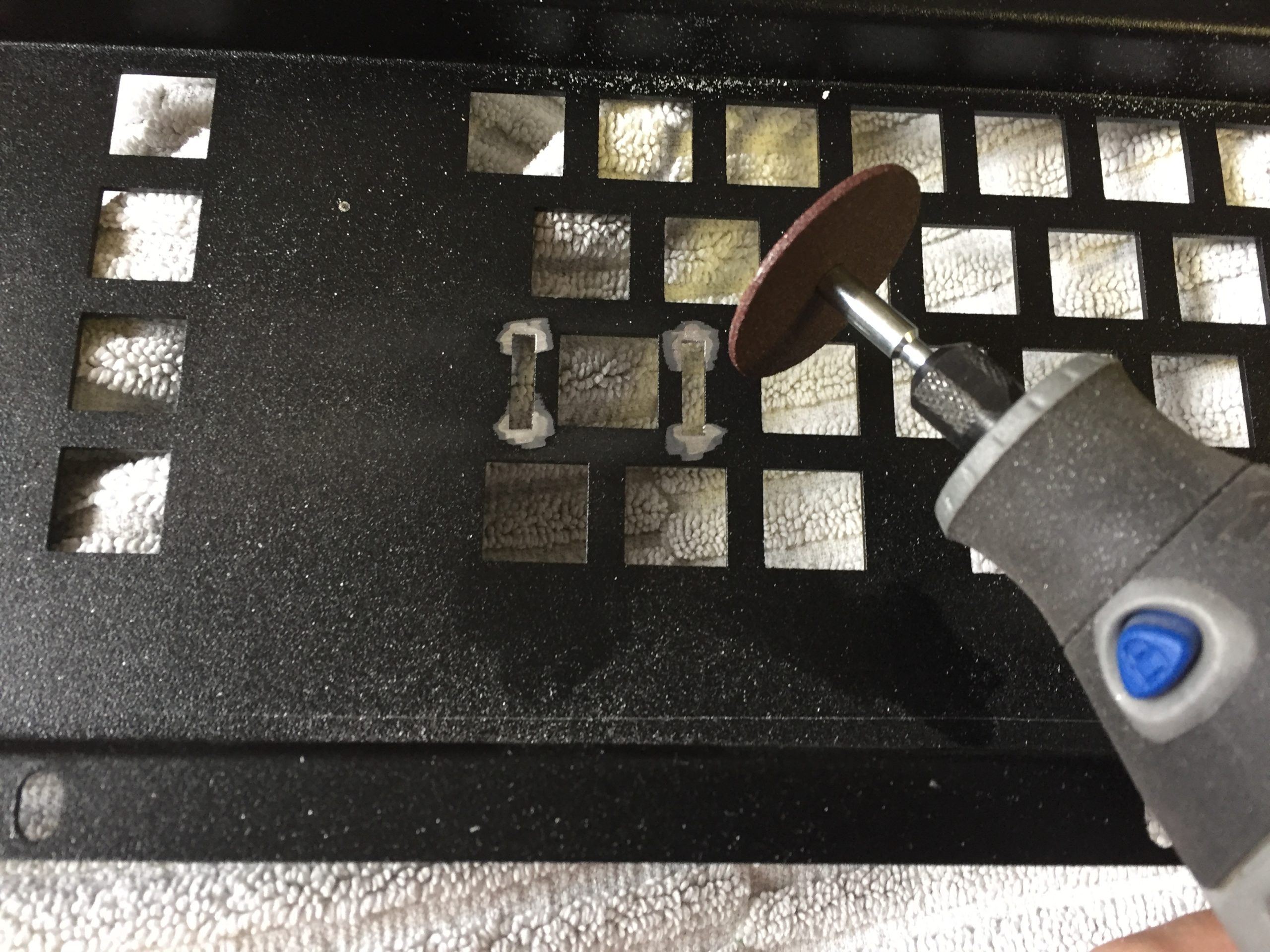
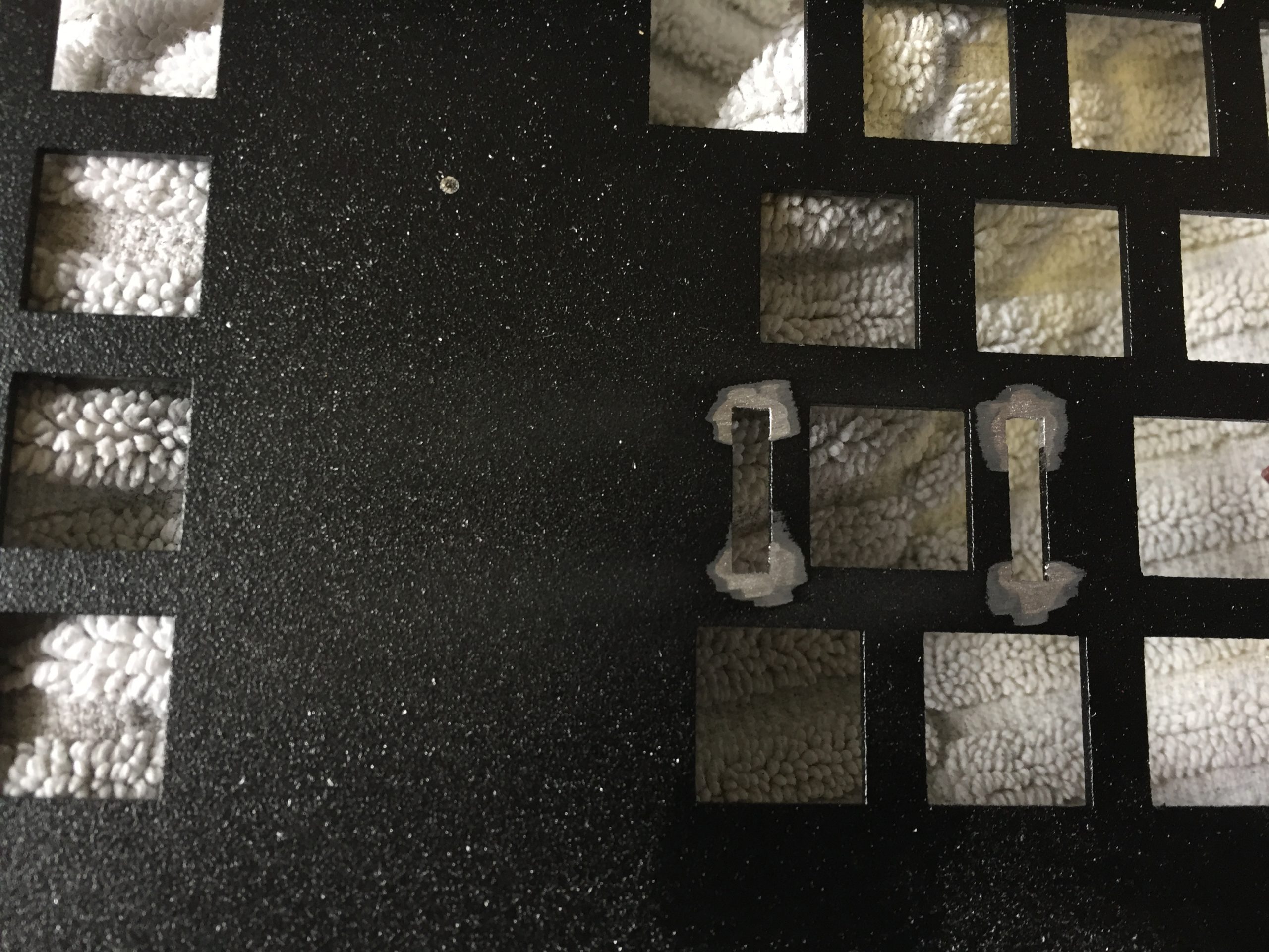
If the bracket is powder coated, the coating adds to the overall thickness of the bracket. This will not allow the Costar plate inserts (Space bar and Return keys) to snap correctly into place. Using a Dremmel can be used to remove the excess powder coating to make a perfect fit.
Cables
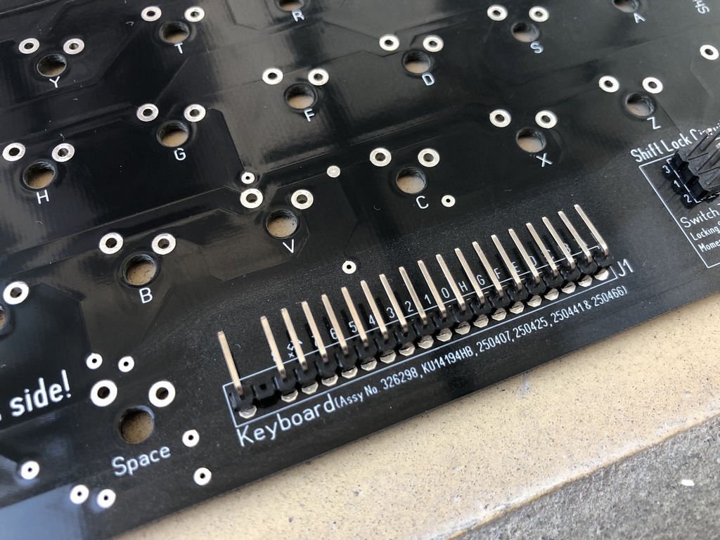
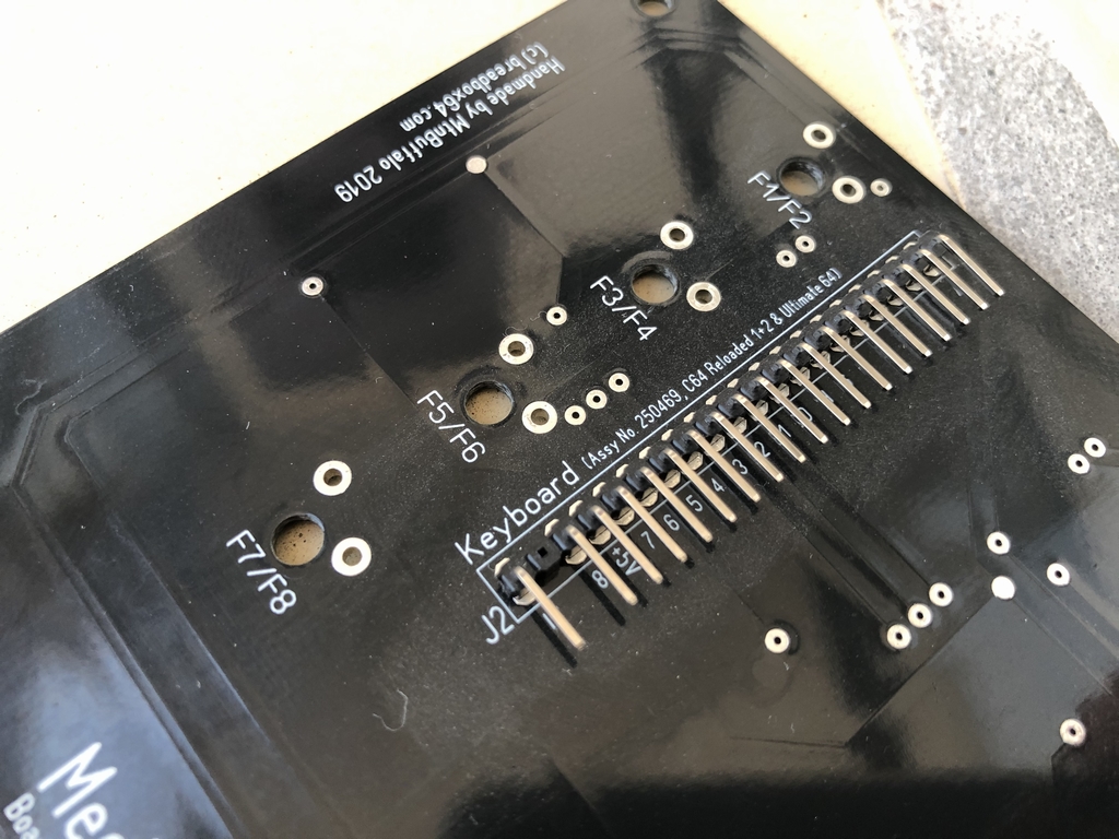
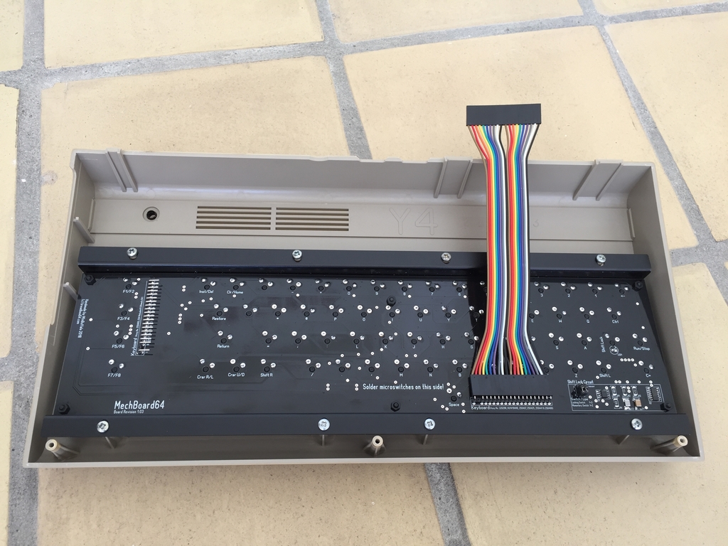
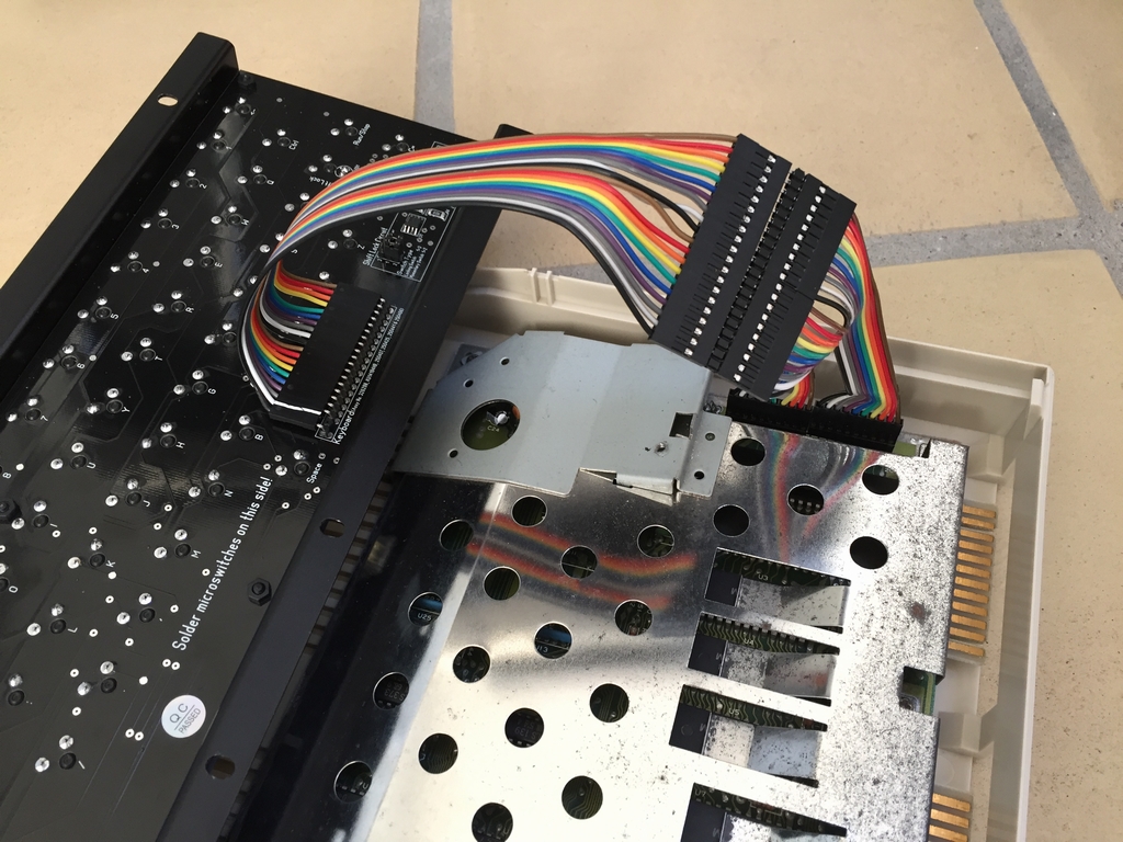
A 20 cm ribbon cable is used to connect the MechBoard64 to the motherboard of the C64. Depending on the C64 motherboard version, use the pin header that is the closest to the socket on the C64. Text near the 20 pin pin header indicates what motherboard each pin header is best suited for.
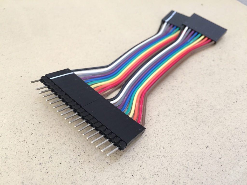
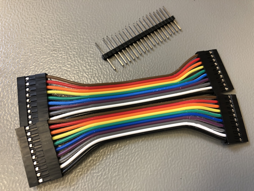
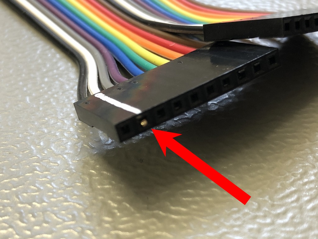
Commodore 64C slim cases with long boards installed (e.g. Assy 250466 and 250425) place the keyboard pins on the C64 motherboard quite far from the keyboard pins on the PCB. A 10 cm extension ribbon cable will make it work. The cable can be made from two 10 pin cables and a 2.54mm pitch male single row straight pin header. I’ve makred the cable and added an extra pin to make sure it was not inserted incorrectly. The cables can be found on Ebay.
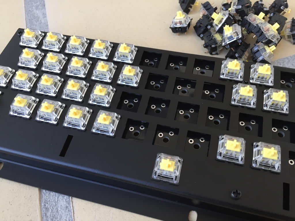
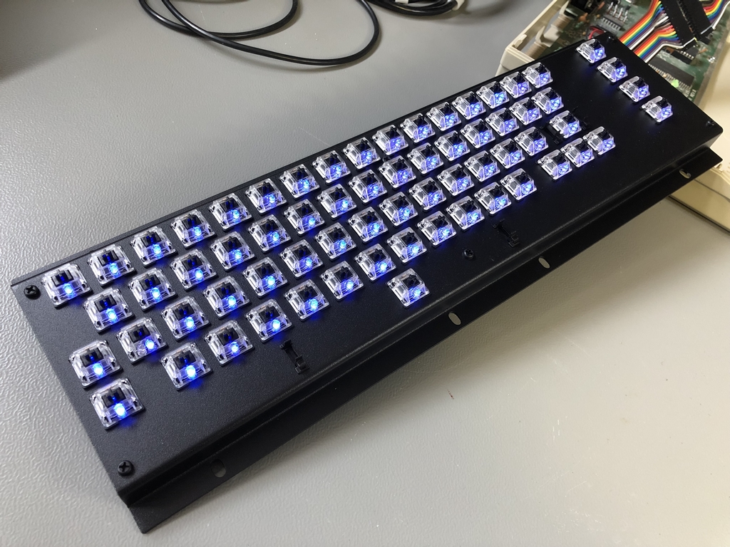
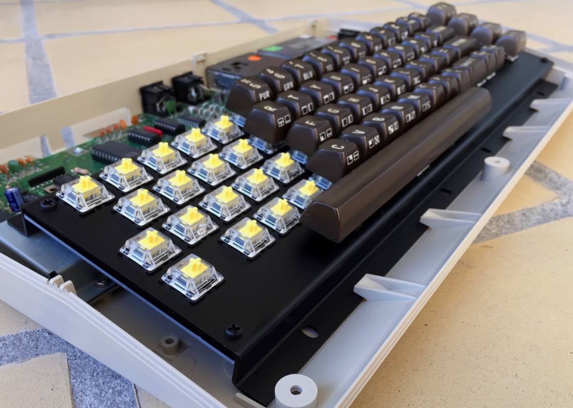
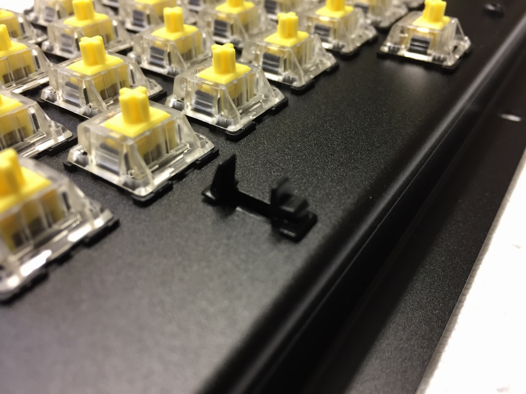
Microswitches
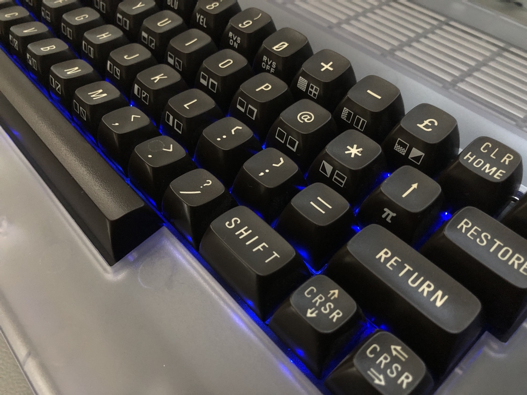
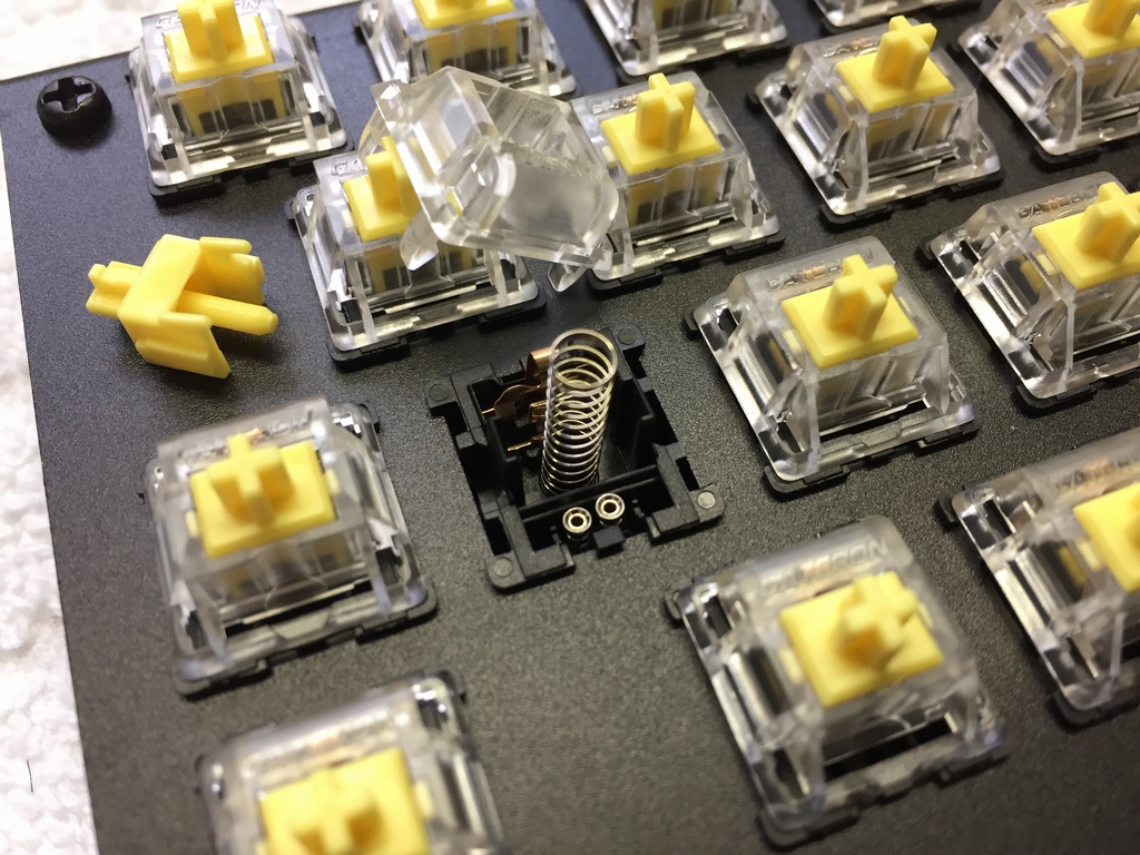
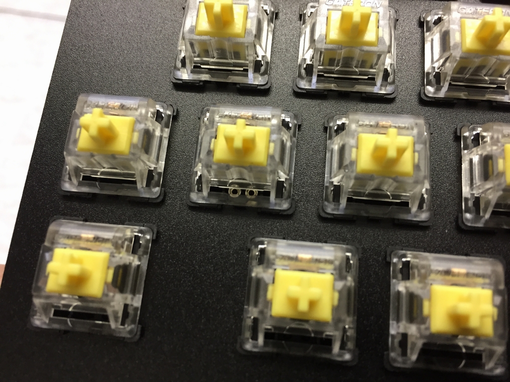
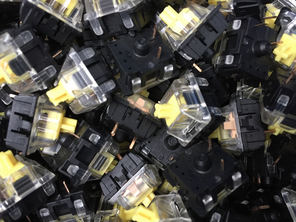
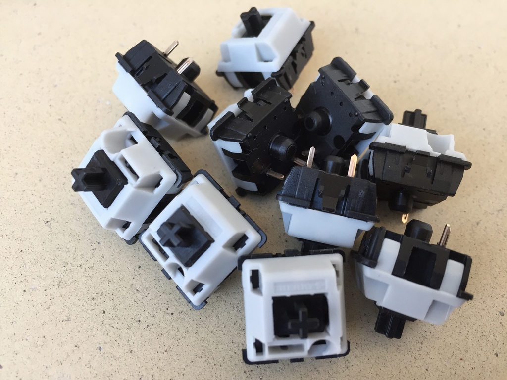
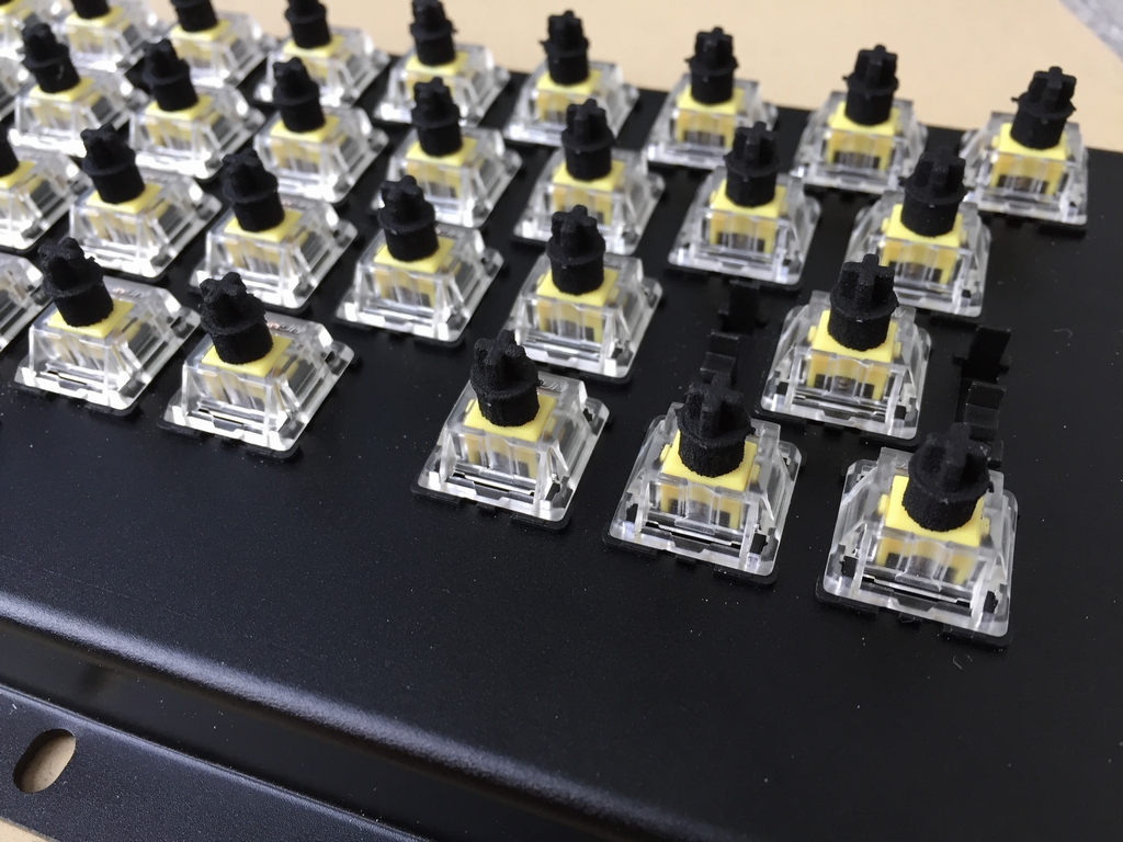
The MechBoard64 use Cherry mx style switches including switches from Gateron. I have found that Gateron yellows (55 g linear) resemble the original C64 keys the best. The microswitches can be found in numerous webshops.
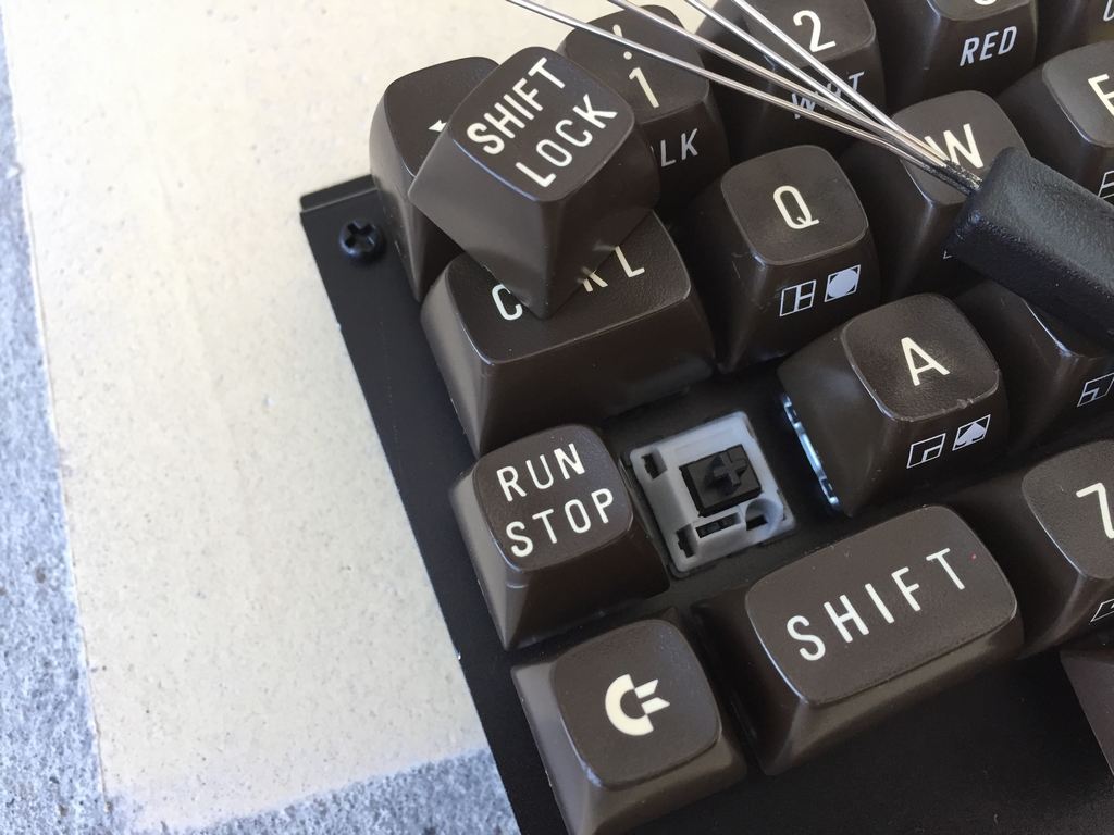
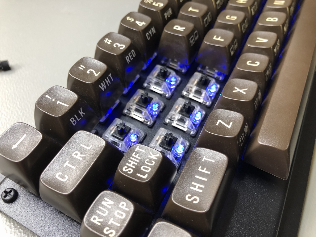
The Shift Lock can use either a standard non-latching microswitch like the rest of the keyboard (using the Shift Lock circuit) or a Cherry mx Locking switch that bypasses the Shift Lock circuit.
3D Printed Keycap Adapters
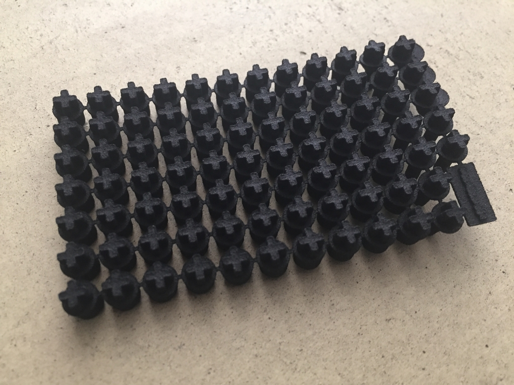
To use original Commodore 64 keycaps with the stems of modern day microswitches, 3D printed key adapters are needed. The keycap adapters can be printed by e.g. Shapeways in a material called Strong and Flexible which is also known as Nylon Plastic, PA12 or Polyamide. If using Shapeways for the 3D printing process, make sure to have them done as a ‘prototype’. Otherwise the print may fail their quality control…
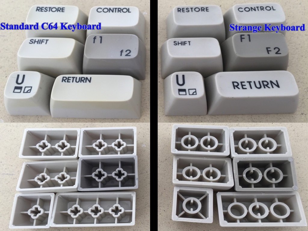
Please note that the 3D printed key adapters only work with Cherry mx style switches and the standard Commodore 64 keycaps. Other C64 keycaps, like the strange ones shown below, will not work and hence cannot be used with the 3D printed key adapters! The same holds true for keycaps found in Commodore VIC20 keyboards that some of the early Commodore 64 keyboards came with (link).
Keyboard Stabilizers
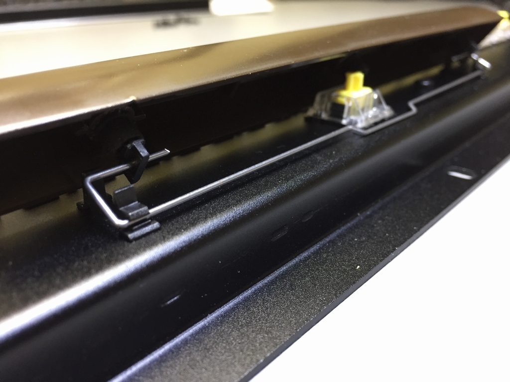
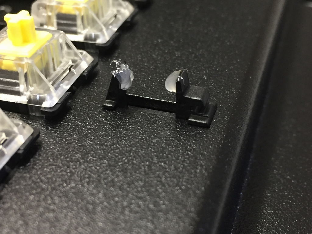
The keyboard stabilizer system uses Costar keycap inserts and Costar plate inserts. The Costar inserts are needed for the Return key and the Space bar. These can be found in various webshops.
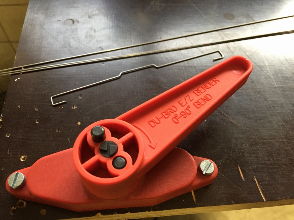
The size 2u stabilizer wire usually comes with the inserts. However, the stabilizer wire for the Space bar is size 9u and have to be made by hand. I used a DuBro EZ Bender no480 tool and a 1.00-1.09mm piano wire to make them.
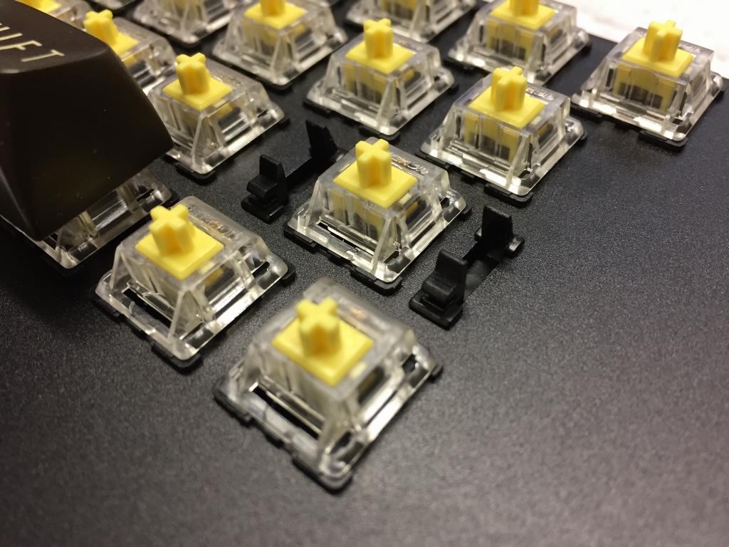
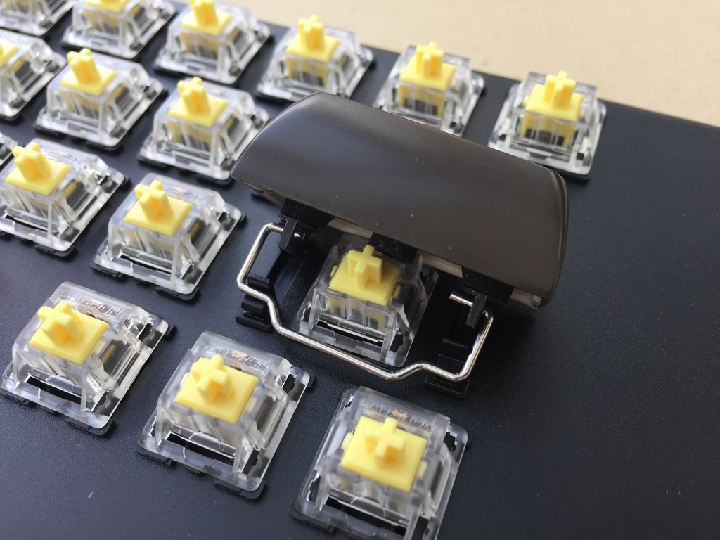
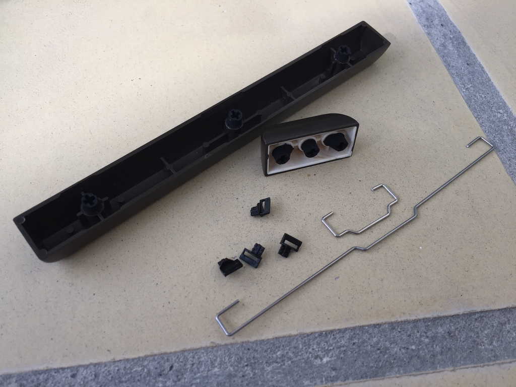
SuperLube can be added to the Costar plate inserts to make the travel of the keys even smoother.

Miscellaneous Parts
Spacers
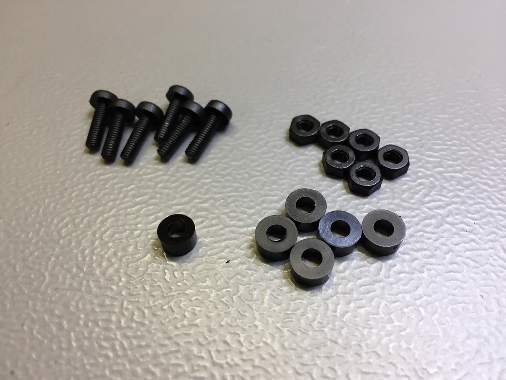
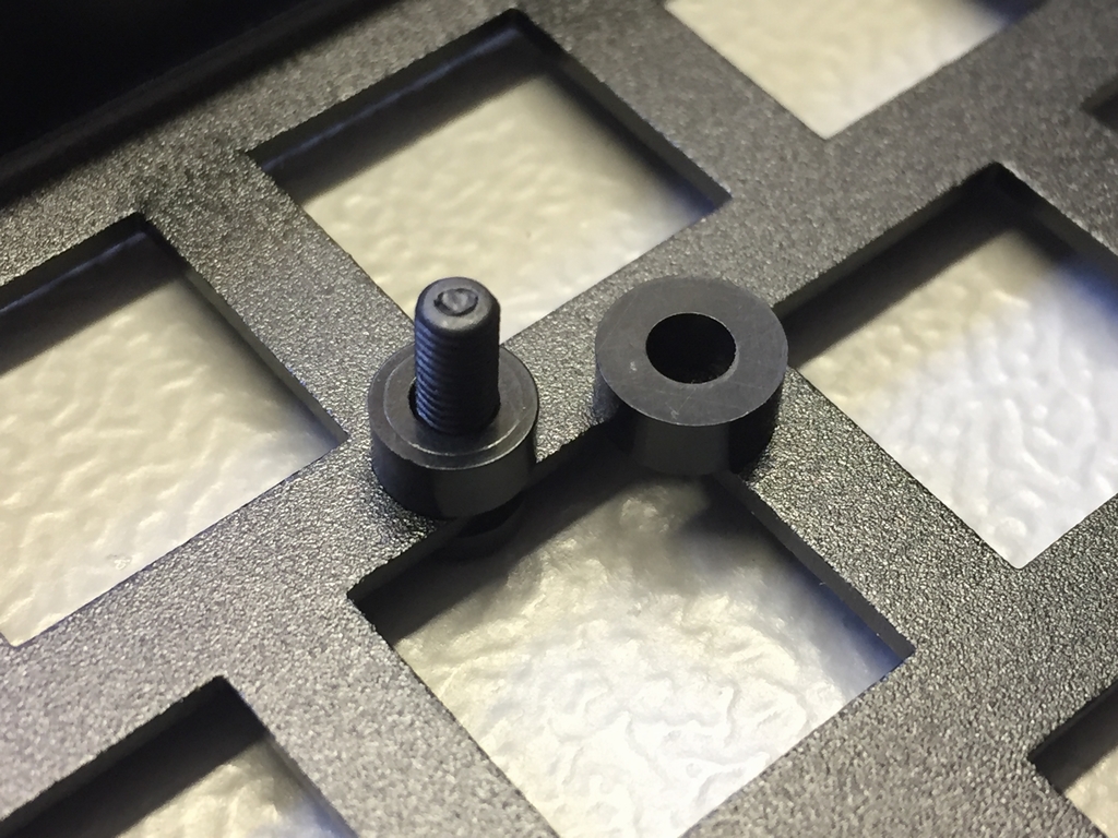
The PCB is assembled using plastic screws/bolts (M3 x 10mm), plastic nuts (M3) and plastic spacers (M3 x 3mm). The spacers should be 6-7mm in outer diameter. It is important that one of the spacers are no more than 6mm in diameter as this is the maximum size that will fit the top row, center hole.
Supported LED Types
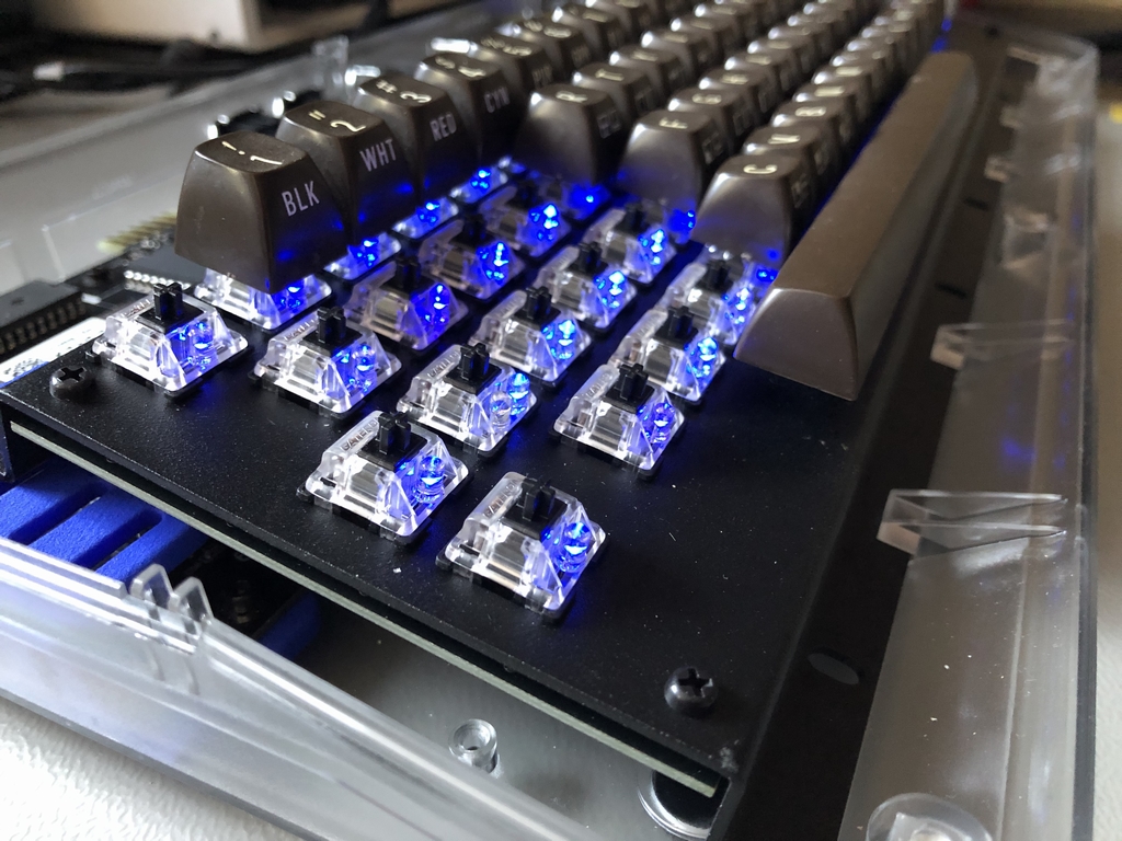
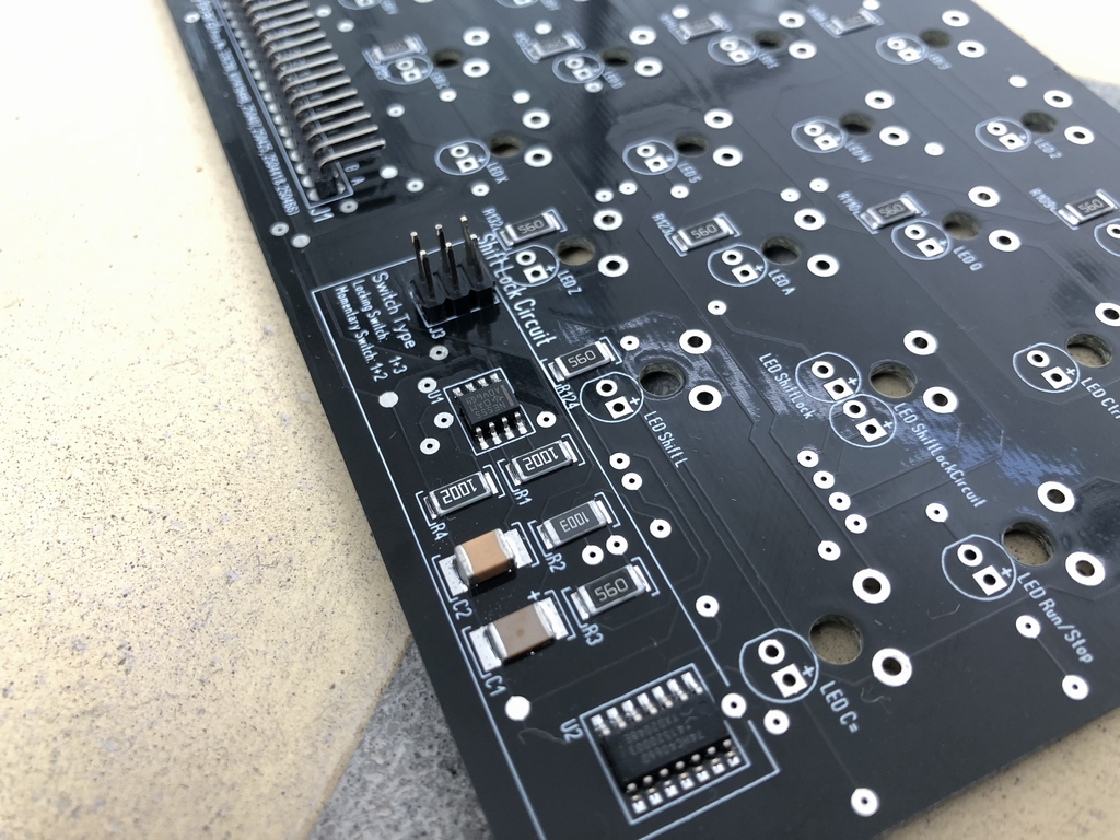
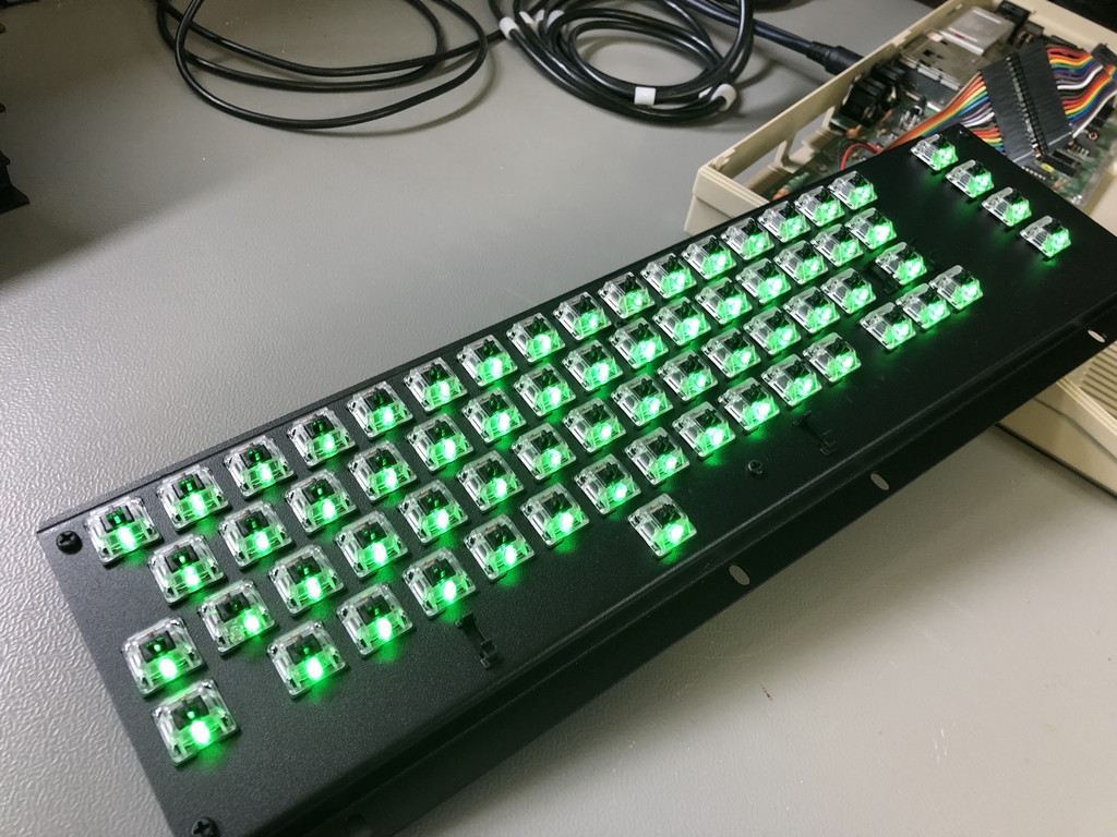
If making the MechBoard64 – Light Mod Edition, 66 3mm LEDs should be used. The forward voltage of the PCB is 2.0VDC. This is the same voltage that the ShiftLock circuit LED gets. In this context, e.g. blue and green colored LEDs usually support a forward voltage of about 3.0VDC while red colored LEDs only need around 2.0VDC. To keep things simple, I simply went with the 2.0VDC using 56Ω resistors. This will obviously reduce the amount of dissipated light from LEDs which can handle a higher voltage. It should be noted, that if e.g. 0Ω ‘resistors’ are used instead of 56Ω resistors, the forward voltage will increase to about 2.5V and hence increase the strength of the illumination. This will only work safely if the LEDs can handle at least 2.5VDC!
Assembly Instructions
A manual on how to assemble the MechBoard64 can be found here (link).
Complete Overview
A complete overview of all published data regarding the MechBoard64 on this site can be found here (link).
Final Comments
I truly hope to see some nice modifications of the MechBoard64. Ideas that I’ve never thought of and will be proud of being a little part of. Good luck with your MechBoard64 projects!
© breadbox64.com 2021
Thanks for sharing this. I’ve been wanting to make one of these for a long while.
I love this project and want to try putting some together. I already received a quote for the keyboard brackets. Now I am trying to order the PCBs. Using your direct link offers me to add the PCSbs straight to my cart. However, when I do that I am basically ordering an empty PCB, because the Gerber files are not transferred over. I downloaded the Gerber files directly from here, and I can upload the Gerber files to make that order, but I am unsure of all the individual settings like thickness, hole size, track distance, etc. I also opened a ticket with PCBway why it’s not adding correctly to the shopping cart.
Hi Sascha, sorry to hear that you have difficulties ordering the MechBoard64 PCB. If you use the direct link to PCBway you will get an empty PCB, but without having to worry about PCB thickness, color, vias etc. This approach uses the exact Gerber files I’ve used for my own MechBoard64s. On the order page there is also the BOM file (parts list) which should give PCBway enough information to assemble a complete PCB with components. I have never ordered anything from PCBway using their ‘shared projects’ section before. So I cannot help you much 🙁
Would you be kind and share your experience here for others who may get ‘stuck’ like you did? Thanks.
Hope you get it all working! Good luck with the project!
Good on you for completing this project. At one point I thought, “wouldn’t it be cool if…”, but you actually went and made it happen. Very nice. Who knows, now that you’ve done all this work, maybe the folks who make the new C64c cases will manufacture these keyboards and order a run of keycaps. Then they would have complete chassis for rebuilt original boards, new boards, and raspberry pi or other emulators. That possibility is pretty neat; the C64c is about as ergonomic as any other keyboard, save the unusual special key layout itself, so it’s not like it’s some weird product with super specific uses.
Anyway, thanks for being awesome.
Thanks for your kind words. Much appreciated 🙂
I received a reply from PCBway.
“ I have checked this link but the original author has closed to share this project so that it cannot upload the file.”
I’m sure that’s just some weird project setting that’s incorrect.
I have an additional question, if you don’t mind.
The 20 wire Dupont cable that you are showing in the picture. Did you make it yourself or did you order it prefabbed? I am asking because I am having difficulties sourcing these.
Hi Sascha, I assume you are referring to the 10 cm extension cable (Dupont cable/Ribbon cable/rainbow cable), right? If so, I’ve made mine using two 10 cm 10 pin cables with a 2.54mm pitch male single row straight pin header for the gender change. You could also use an extra 20 cm 20 pin ribbon cable and the pin header, but this will give you a lot more un-needed cable to hide inside your case. I’ve added a few extra images in the post for your reference. Hope this makes better sense 🙂
I’m not sure what PCBway are referring to with their comment regarding the shared project. However, I’ve added all the Gerbers + Centroid file to the shared project on PCBway. Hopefully this will fix the issue.
You are awesome! Thank you for sharing.
If someone offers a modified version suitable for use with off-the-shelf keycaps (link), I’ll happily purchase one 🙂 Unfortunately, I’m definitely not a hardware guy.
That fixed it! Thank you so much! This really is an awesome project and I can’t wait to have all the parts here to start building this.
Hello again! I’m sorry for all these questions. Please bear with me. I ordered the PCBs from pcbway earlier today, and they came back with a question. This is what they wrote:
There is a solder ring on the top layer of the circuit, and there is no solder ring on the bottom layer,it will damage the drill when spraying:
1. we make as immersion gold but the price may will more expensive.
2. We add a small pad on the side without the pad (the bottom layer) (0.15MM larger than the single side of the hole)
I assume option 2 is the way to go, but I wanted to check with you first.
Thank you!
PCBWay came back to me with questions for assembly only regarding the pin headers (“missing” pin on pos 2).
Looks like they got it correct and are just asking to be sure.
I was not asked those questions Sascha has been reporting, though.
Hi Baker, the BOM file, on the right hand side of the PCBway projects page, holds images of the pin-headers (J1 and J2). Double check that they provide the correct version of the pin headers – they didn’t with me the first time…
I’m not sure what issue PCBway has asked Sascha about. They have created the exact same PCB that is on the project’s page without any issues. I’ve PM’ed Sascha and will report back whatever the problem was when I get a hold of him 😉
Thank you for the heads-up. They came back with something like this: 1*20pin 2.54mm 90°degree.
I know there are two types of angled pin headers, one that sits much closer to the pcb.
I will report back on that issue here when the PCBs arrive.
Happy to hear that you are aware of the two types of 90° angled pin-headers 🙂 For those who don’t, here’s an image of the differences… (link)
Hi Sascha, apparently PCBway has issues with the bottom layer of the SIP sockets for the LED for the Shift Lock key. They want to have solder pads on each side and not only on the top of the PCB. What they should do is simply put in vias like in this image (link). Try and send that image to them. This should work 🙂
Hi. Great news that this project is now open!
I have a question about the Keyboard Bracket. Is it possible to just purchase a single or low numbers of them, or is there a minimum quantity to consider? Would there be a certain ammount where volume pricing comes into play?
Maybe this info or general info about this could be added in the main text above so the Chineese firm doesnt get spammed by requests that goes nowhere if one really has to buy 100 or more. Thanks.
Hi Bandaren, I have purchased low numbers of brackets from the Chinese company mentioned in the post. So that should be possible. However, I remember them trying to sell me a larger number at a reduced price. So I guess both small and large quantities should be possible 🙂
Hi! I have a 3D printer and I want to know if I can print my own adapters. The nylon material is pretty hard to print in common printers and you need to make some improvements that cost a lot of money. So basically my question is, in which more common material can I print the adapters without damaging the keycaps or something? Thanks in advance.
Hi Rick, I don’t have much experience with 3D printing. I’ve used SLS prints as these have a high dimensional precision. That being said, why don’t you try and make the prints with your printer and see how they fit? You can quite easy check if they are too tight or too loose without destroying anything 🙂
I am still missing the PCB but got the rest of the parts and did some test fittings. I was able to fit the Costar inserts without any grinding or modifications to the aluminum base and wanted to share. So before you grab a grinder you might want to check if you can fit the inserts right from the start (link). It takes some pressure but no excessive force and they sit nice and tight.
Thanks MtnBuffalo for making all this such an enjoyable experience.
Wow, that looks really good! Happy to hear that no grinding was needed to make the Costar inserts fit. Nevertheless, I recommend that you double check that the Costar plate and keycap inserts run smoothly before soldering everything together. That makes small adjustments a lot easier 😉
Thanks for sharing!
Ok, now I got news from PCBWay. It really looks like they got the right pin headers.
But… something is strange here 🙂 (link)
So even with the pictures provided in the BOM list, they got this detail wrong and mounted the pin header pointing in the wrong direction.
Just Ordered the PCBs. Gonna give this a shot! Thanks again Mtnbuffalo
Will the shift-lock LED work with a locking switch or only if the shift-lock circuit of the PCB is active?
Yes, the LED only works when the Shift-Lock circuit is active. When using a locking type switch, the header caps must be set correctly to avoid unwanted effects by by-passing the circuit.
So with the stock pcbway setting the board will come as bare green pcbs? what do I need to change to have them assembled? having them come in black seems easy enough.
Anyone having the brackets made? I’ll go in on an order with you if someone wants before I order my own.
Hi Ken, it should be fairly easy to have PCBway assemble the PCB with all the electronic parts. The uploaded project holds all the information they need to make a complete board. This includes the BOM file, assembly images and Centroid information for the assembly robots. However, you may have to specify that when you order. I know others have been able to do it without too much trouble 🙂
Good luck with your MechBoard64 project!
In case anyone is interested I’ve sliced-and-diced MtnBuffalo’s illustrator file into something 3D-printable: https://www.thingiverse.com/thing:4591235
This is sized to fit on most consumer printers (200x200mm bed) and be superglued/epoxied together when finished. You could probably have it printed by one of the commercial printing services too, but it’s big so it’ll probably be expensive. (I would do a full-size version too but TinkerCad can’t handle something as wide as a keyboard.
My fit-tests need a little finesse with sandpaper or a file so the keyswitches snap in, but if your printer is dialed in a little better than mine you may not need to. You will have to drill the holes to mount it to the C64 case yourself for now but I expect to do one more revision where I add those.
Hi voretaq7, very nicely done! Looking forward to see a finished MechBoard64 with a 3D printed bracket as an alternative to the metal ditto 🙂
Just a quick note that I’ve posted what should be the final rev to the 3D printable key plate @ https://www.thingiverse.com/thing:4591235
This version includes (way-too-wide) mounting slots for the screws and should be able to be screwed in to any C64 case once printed and assembled. The slots are untested (because I drilled my prototype for mounting), but I did line them up with the screws in a test print.
Assembled photos have also been added – still waiting on keycap adapters for a final glamor shot.
If there’s interest I might kick out a revision of this design that’s suitable for use with modern Cherry MX keycaps. Looks like that would need the brackets to be about 6-7mm taller to get the same typing height as the C64 keycaps. A fully “modern keycap” compatible design would require changing the PCB layout of the 1.5U and 2U switches to be where modern caps expect them (centered under the key), and that’s beyond my scope 🙂
voretaq7 – as well as everyone above – thank you!
🙂
Hello. Thanks to all, MtnBufalo, and the voretaq7, for the above! genius! One question sourcing the costar parts, I am in the uk and cant find a definite supply. Does this include the correct parts? link …or can someone please provide a link or ebay source? TIA!
Hi there, the link you refer to contains all the Costar parts needed except for the size 9u spacebar stabilizer. You have to make that yourself 😉
Thanks!
If I use the PCBway “pre-saved project” link can I just select “Add to cart”, will that also include the components for the electrical circuit and assembly of the components without me have to add or check any additional boxes?
Hi Stefan,
Yes, you should be able to simply add the project to the cart. However, please go through the list of PCB options (color, thickness, open vias etc.) to make sure everything is as it should be. It should be as easy as adding the project to the shopping cart. That being said, I have not tried ordering the boards this way so maybe others who have may be able to give their two cents?
I was able to order the CPB without any problem. It took some time to figure out the process but after that it was easy.
I’m trying to get in touch with Shanghai Yinuo Machinery Co for the order of an aluminum bracket, so far, no reply. Does anybody have one that they would like to sell or know a different place where to order one from?
If I decide to order a 3D printed bracket from Shapeways, what would be the best material to use? Would it be a good substitute for an aluminum bracket?
Any suggestions for a place that has the Gateron Yellow switches for reasonable price, I found them on Amazon and eBay but the delivery date is for next year…
When uploading the keycap adapter 3D printing file to Shapeways, I assume I should use “mm” right?
The 9U space bar stabilizer, is it possible to bend the 1mm piano wire with pliers or will you have to use an DuBro bender?
Hi Stefan,
great that you were able to place the order from PCBway without too much of a hassle 🙂
The 3D printed keycap adapters .stl file is in millimeters (mm).
I would think that it is possible to bend the 9u stabilizer using pliers. It may take a few tries, but it should be possible 🙂
Good luck with the project!
Hello all, has anyone 3d printed their own keycap adaptors using Cura slicing software? If so, could they please confirm if they fixed or ignored the warnings made by Cura? i.e. when I load the .stl, warning: “Model errors: your model is not manifold.” Also, which way up did you print? Which support structures did you use? And did you find PLA OK for the task?
Lots questions but now on my third attempt to print that 🙂
Thank you!
I’m happy to inform everyone that I was able to find a US based company that was able to make the aluminum bracket. The bracket is just perfect and I could not be happier and Dan was super easy to work with. I did not powder coat my bracket but I will spray paint it later.
I was also able to convert the Adobe .ai file to the more common .dxf file that the cutting/forming companies uses (I will see if MtnBuffalo can get it added to the project files).
Contact info:
Laser Cutting Company
Dan Friedly
DanF@lasercuttinginc.com
PH. 586-468-5300
42300 Executive Drive
Harrison Township MI 48045
Hi Stefan, thank you for providing info on a US based company that will also make the brackets 🙂 Your .dxf file has been added to the .zip file. Thanks!
Anyone that knows how to troubleshoot the MechBoard64? When I test the leads on the left Shift and Shift Lock switches I get a “closed circuit” and when I plug in the keyboard to my Docking Station for my Turbo Chameleon 64 V2 I get the error “release key”, it think something is holding down one or more keys. I desolder both switches and the LED but I still have the same issue when I plug it into my Turbo Chameleon 64 V2 I waiting for my Ultimate 64 Elite board.
Hi Stefan, have you tested the keyboard in a real Commodore 64 as the issue may be related to the Docking Station / Turbo Chameleon 64 V2? You can also double check that the two header caps near the Switch Lock Circuit is set correctly. Also the Shift Lock Circuit needs 5VDC to operate correctly. The Keyrah from Individual Computers doesn’t have this natively – maybe the same holds true for the Docking Station…
Thanks MtnBuffalo!I will try it with a C64 Reloaded MK2 board. So when the board is fully populated and unplugged, the leads on the Left Shift and Shift Lock should indicate a closed circuit when you test it with a multimeter in a “Continuity” mode?
If the two headers caps inside the Switch Lock Circuit area are set to ‘Locking Switch 1+3’, then you should have a closed circuit between the Left Shift and the Shift Lock 🙂 You can see the connections in this image of the PCB (link, link).
If you plan to use the Switch Lock circuit with a momentary microswitch (and moved the two header caps accordingly), then you should not have a closed circuit 😉 This option needs 5 VDC to drive the Shift Lock Circuit…
If you have access to a Doctor64 you’ll be able to see what specific keys are actually being held down as in this image (link, link). This may help you in the search of the location of the short curcuit.
Good news, MtnBuffalo you were totally right! The Chameleon 64 V2 Dock does not supply the 5VDC as needed for the MechBoard64. As soon as I plugged it into my C64 Reloaded MK2 board it all worked as it should, now I get the indicator lights for SHIFT LOCK enabled when activated. I tested all the keys and they all worked!
-Thanks
Hi Stefan, happy to hear that you got it all working 🙂
Amazing work on this project!! Just placed an order with PCBWay. Let’s see how it goes! 🙂
I see you shared the Gerbers, that’s great and all. Any chance you’d share the shematics and board layout files? What software did you use, KiCad?
Hi UnaClocker, the schematics can be found online 😉 I used Sprint-Layout 6.0 for the PCB layout. The file can be downloaded here: link. Good luck with the project!
Hello, Does anyone have a source for the Dupont cables used in an original MechBoard? Every one I have come across on eBay (and other sources) have the connectors separated into individual wires at the end, versus being all joined together. Thank you!
Mkrik – I couldnt find any either. In uk, I used two of these – perhaps the description will help you find suitable in your location. cheers! link
Another call for help please re the 3d printed adaptors. When I load the .stl into cura, it still reports as ‘not manifold’.. ie there’s gaps or holes in the file. Also, the orientation appears odd, in that most of the parts are not touching the base plate, and the circular base touches the square frame of the gaterons. I’m about to try a different model from thingiverse. BUT! – first, has anyone any tips to print this? Did you have to change the model for an ender-3 or change anything else in cura? TIA
Hi all, Just as an update and an end to my 3d print woes. My solution was:
a) I found a rectangular c64 key adaptor alternative on thingiverse and printed that. I found that was more solid in the switch and replicated at the exact size needed. My ender printer printed those as set from the factory, no recalibration or cura zoom needed.
b) I studied the pics more carefully to appreciate just which of 3d printed adaptor parts are needed for which key; the sloping ones for the costar inserts, the thin long ones for support duties on the F and shift keys etc
c) I modified those in tinkercad to print in batches, cutting out and rotating the necessary adaptor supports from the model set already posted here
Result: a complete, beautiful and working keyboard! I used Gateron blues in my second try as I prefer the more modern (sorry) ‘mechanical’ feeling of those over the ‘smooth’ yellows.
Thank you again to Mtnbuffalo, plus voretaq7 for the 3d mounts!! Thank you so much.
I’ll send some pics
BOB
I also had trouble finding the 20 cm 20 pin cable, but finally came across it on eBay: link
I have now ordered all the parts except the PCB. I am waiting for the audit of the assembly service. As the minimum number of PCBs is five, I think I will be ordering 5 pcs of assembled PCBs, if the quote from the PCBWay is reasonable.
Thank you MntBuffalo for an awesome project!
Does anyone have a source for the Cherry latching switches? MntBuffalo, I am assuming you no longer have any as your links go to a “page not found”.
Hi Greg, yes, the few Cherry Locking switches I had are all long gone 🙁
Has anyone had issues with the 3D printed adapters from Shapeways? I have made two keyboards, one a few months ago, and a second a few weeks ago. Both times, I used Shapeways, PA-12, as recommended. The first order fit flawlessly onto the microswitches, the second batch, though, was impossible to make fit onto the same Gateron yellows. Shapeways couldn’t figure out what the issue was, unfortunately.
@Bob_Onions, can you share the .stl file you used to print from your ender? Very much appreciated
hi Dwestbury, sure but …how! If you can share a location or an email address I’ll gladly share
Bob
I’m still looking for someone reliable that can cut and bend the aluminum frame. Very few of the services I’ve contacted have been responsive. I’m guessing they’re not interested in a small order quantity. I was able to get a modified version of the Illustrator drawing uploaded to OSHCut as an SVG file. Their website tool enables you to select the bends and shows you a nice 3D rendering of the result, which is great. However, they want $145 USD to make a single frame, because half the price is tied up in tooling. It seems you would need to make ~10 frames to bring the price per unit price down to $50 USD with them (for a $500 order total). So I’m left to wonder whether there are better (more economical) options out there or whether I should find 9 other people willing to chip in to buy some frames?
Dwestbury, following up re models. I found these fitted the clone cherry switches much better: link
I duplicated it in the slicer so could print 20 at a time. they are stable, though a bit fragile… but do the job after a few seconds sanding of the sides. I obviously still used the vertical support models as per the site, above.
The 3d printed keyboard support kindly provided by the chap above worked fantastically. If you can’t find someone to bend aluminium, I’d definitely suggest printing it… in my view its perfect.
I bought #5 of the originals built by @MtnBuffalo and am about to build one by hand having recently sourced most of the parts. For anyone embarking on this adventure, it’s worth noting that the plastic screws and nuts are easily purchased but the spacers, it’s a lot easier to 3d print them. Resin or FDM are both fine.
I printed my adapters in PETG and they worked more or less fine – none broke, but the tolerances were incredibly tight. They did, in the end, snap in to the keycaps in a satisfying way, and we’ll see if they fit onto the switches nicely after they’re soldered. I am pretty sure they will, one of them test fit acceptably.
Having it to do again (and I very well may), I would probably opt to resin print the adapters or get a friend to do it for me. This project in fact could be bundled into a good excuse to buy a resin printer if you don’t have one already.
I have a question. I am putting together a Mechboard 64 LED edition for a SixtyClone board I am making, and some of the LEDs are not lighting, and always two together in a row. (W,E), (Y,U), (P,@) all on row 3 and (C=, Left Shift) on Row 1. Checking continuity to the nearest resistors on either side is showing connection and when I attach leads to a 2032 battery to make sure I installed the polarity correctly when soldering the buttons on, they are installed correctly (positive to + thru hold on the board), so I am at a lost at to what may be causing this. Do you have any idea?
Hi Robert, sorry to hear that you are experiencing issues with your MechBoard64 Light Mod build. The LED circuit is really rudimentary and works independendently from the functionality of the keyboard. All LEDs are ordered in pairs. Each pair is directly fed by the ‘+5V’ line on the keyboard connector. Each pair is connected in series with a resistor to keep the voltage down. All resistors are connected directly to ‘ground’ using the ‘I’ connector on the keyboard plug. There is therefore not many things to try that you have not already done 🙁 However, for good measures you could try checking these steps for fault finding.
Continuity:
Test that all LED resistors are connected to the ‘I’ terminal on the keyboard cable connector.
Test that all LED pairs are connected to the ‘+5V’ terminal on the keyboard cable connector.
Test that all LED pairs are interconnected -> ‘LEDx-‘ to ‘LEDx+’ terminal.
LEDs:
Test each LED with a battery before adding them to the keyboard. Check that they are installed correctly (longer leg to ‘+’ and shorter leg to ‘-‘)
I have double checked the pairs of LEDs that you mention. However, none of them are interconnected in a way that e.g. a broken trace will affect the other pairs. Hope you get it working 🙂
Heya thanks for the great article! I am in the process of sourcing all the materials and had a question about the LEDs. You mentioned blue runs around 3V DC but the incoming forward voltage is only 2.5 VDC. Does that just mean I will be under-driving the LEDs and should use a 0-ohm resistor? Or do you still recommend the 56 ohm resistor?
I was looking at getting these guys: link.
Hi there, If you know that your LEDs can handle at least 2.5V I would use ‘0 Ohm resistors’ (or simply use small pieces af wire – whatever works for you…) to get as much light out as possible 🙂 Good luck with the project!
Just seeing if there are any more affordable options for the mounting bracket. I tried going the Shapeways route, but it’s coming in at $112 USD for a 3D printed version in “versatile plastic.” I used this model to generate the quote (link) and as noted in the model notes, there are some imperfections, so I’m not even sure it would work…
I reached to out to Dan, per an earlier comment, as well. Anyone have any luck of late getting a bracket fabricated? Cheers.
The 3D model for the key caps adapters is conspicuously absent from the archive.
Hi there, The file should be in the archive… The 3D .stl file can be found in the folder named ‘3D Key Adapters’ and filename is ‘MechBoard64_adapters_v1_02’ 🙂
Ha. Thanks, I was looking in the wrong spot apparently. 🙂 Very nice project. I have put off building a keyboard for years, because in the end I did not think it was worth the effort, but for a C64, it suddenly makes a lot of sense (I can finally use these blue switches I hoarded). I was wondering if anybody knew where you could get the bracket made without having to mortgage the house. I’m in Canada. Also, if anybody had the bracket made in 3D printed resin or SLS (I’m thinking of using JLCPCB: they’re cheap and my goto fab house for PCBs and small enclosures).
Hi, I posted a 3D printed bracket, in two parts so it fits on your average home 3D printer.
Check this link to thingiverse: link
Is there a version of the board that lets me use the c64 as a mechanical keyboard? I have a few rather damaged c64s in my basement
Hi Metal, I assume you want to use the MechBoard64 with your modern-day PC, through e.g. USB? This can be done as with any original Commodore 64 keybord. All you need to do is mount a Keyrah V2 inside one of your original C64 cases (after removing the original motherboard) and attach it to your pc using an USB cable. I’ve done it previously with a RaspberryPi. You can find more info here: link
Hi there, thanks for the effort you put into this project and even more for sharing it. I am working on an alternative PCB in order to be able to use the Mechboard on a Commodore 16. In fact, while the key layout is the same as the C64, the matrix is quite different. I have already redrawn the board and placed everything, now I would like to replicate the Shift Lock latching circuit but I found no schematics for that in the downloadable ZIP file. Would you mind sharing them? Thanks in advance!
Hi Giorgio, Sounds like a really cool project! You can find the circuit schematic’s here: link
Thanks a lot for the quick reply, I have added the circuit, my board is almost ready, I just need to finish the routing. I also have a couple of suggestions for improving the circuit, send me an email if you are interested :).
My project is almost finished. I have published it at link. I would appreciate if you could take a quick look at the schematics and gerbers (they are in the “outputs” directory) just to make sure I didn’t make any blatant mistakes, like missing holes, etc. Also, do you mind if I name my project MechBoard16? Thanks in any case :).
Hi Giorgio, Looks really cool! You are of course welcome to name your keyboard the MechBoard16 🙂 Happy to hear that you could use some of my ideas. It looks like you have done some nice improvements to the layout of the keyboard. Let me know when you have a working prototype and you are more than welcome to leave a link here 🙂
Hi and happy new year! Just thought I’d give you an update on my project: it took me some time as I decided to add a couple of things, but I eventually completed the MechBoard16 PCB design and ordered prototypes. I put my hands on them yesterday and frantically tested them. I think everything is working as expected (including the Shift Lock circuit, which I modified slightly from your design), which makes me very happy, here’s a couple of pics: https://ibb.co/YLLjFfX, https://ibb.co/rkJCYqh. As you can see I added a few things, for instance I can control every led individually.
I have also made a new 3D model of the bracket and ordered some prototypes (which should arrive in about a month unfortunately) and all the other bits and pieces. At the moment I’m only missing the 3D-printed key adapters, hopefully I will order these this week and then there will be more waiting 🙁
Talk to you again soon! 😉
PS: Feel free to get back to me through e-mail if you want to discuss about my modifications, I’ll be happy to share!
Wow, that looks amazing. Looks like you have put in heaps of hours to make it all happen. Looking forward to seeing the finished product 🙂
Well, the net time it took me was not that much to be honest, it was all surprisingly fast actually! That was probably because some good soul had already done the basic design, taken all the relevant measurements, thought about all the parts needed, taken notes of everything and shared them 😉
(So thanks a lot! I’m really looking forward to seeing this thing completed!)