
It’s finally time to show what has been clutting up my workbench for way too long! Back in 2015 I got my hands on two C64 Reloaded boards (link) and installed them inside cases from the Kickstarter campaign (link). I also entered the Phase5 Indiegogo campaign to get some sweet new keycaps. Thus, all that I needed to have two brand spanking new Commodore 64’s were some new keyboards. So the basic idea was to simply make two new keyboards as no one else seemed to have picked up the idea… How hard can it be, ehh? Well, more than two years have passed since I initiated the biggest Commodore 64 project that I have ever done. Truth is, the project was laying kinda still until a few months back when I decided to just get on with it. Following the presentation of the first working prototype back in March (link), I redrew the bracket and made small adjustments to the PCB. So without any further ado, here is the final version of my new mechanical keyboard for the Commodore 64 – the MechBoard64.
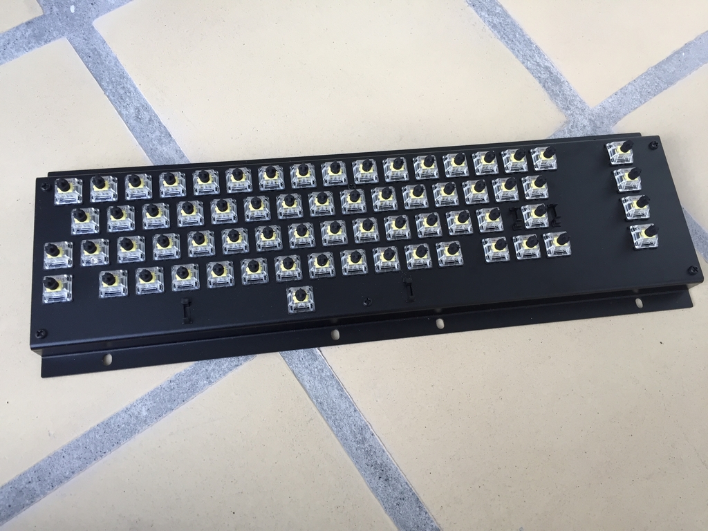
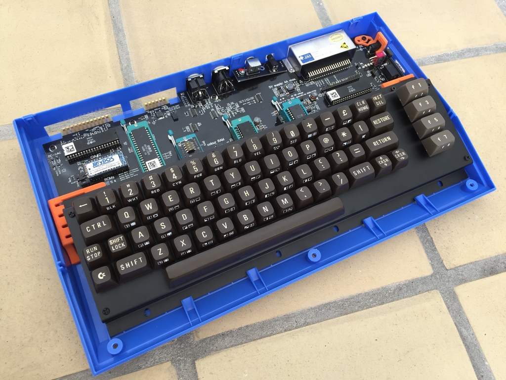
The MechBoard64 is a drop-in replacement keyboard for the Commodore 64, including the new motherboards (Ultimate64 (link) and C64 Reloaded (link)). The keyboard is based on microswitches from Gateron, lasercut aluminum brackets that are anodized in black and a black PCB. The MechBoard64 consists of 123 individual pieces and 200+ soldering points connect it all. This post is an elaboarion of the build of the MechBoard64 for my two C64 Reloaded boards. Hope you’ll enjoy it as much as I did creating it.
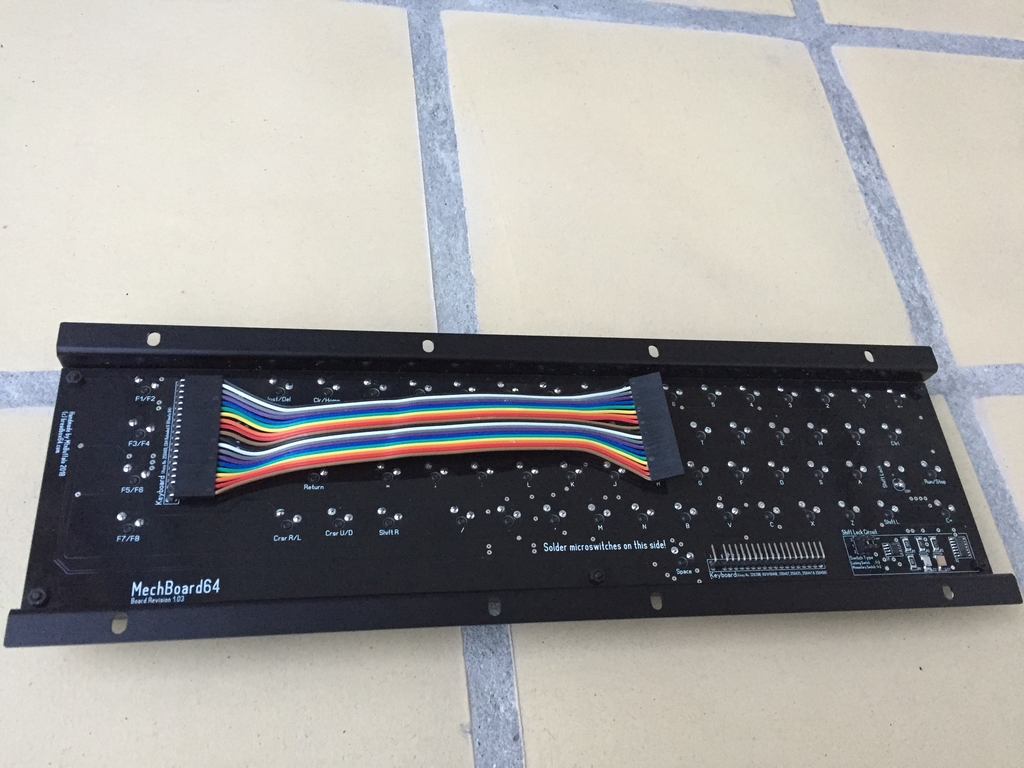
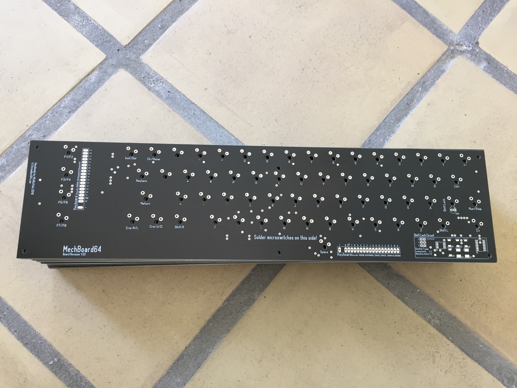
The Printed Circuit Board
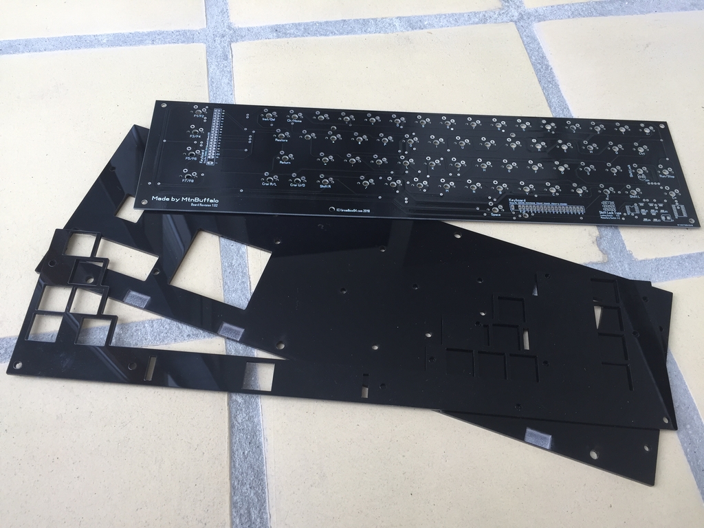
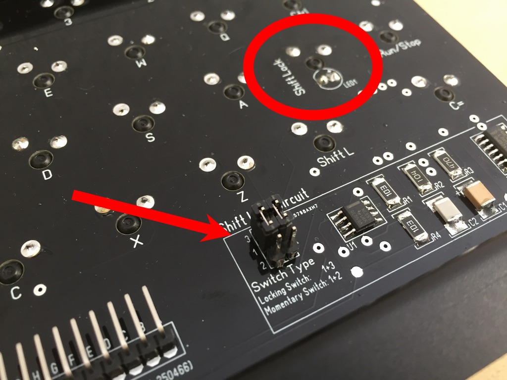
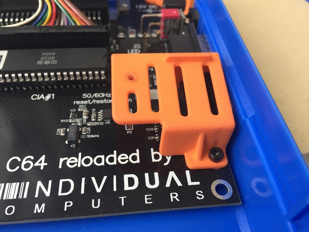
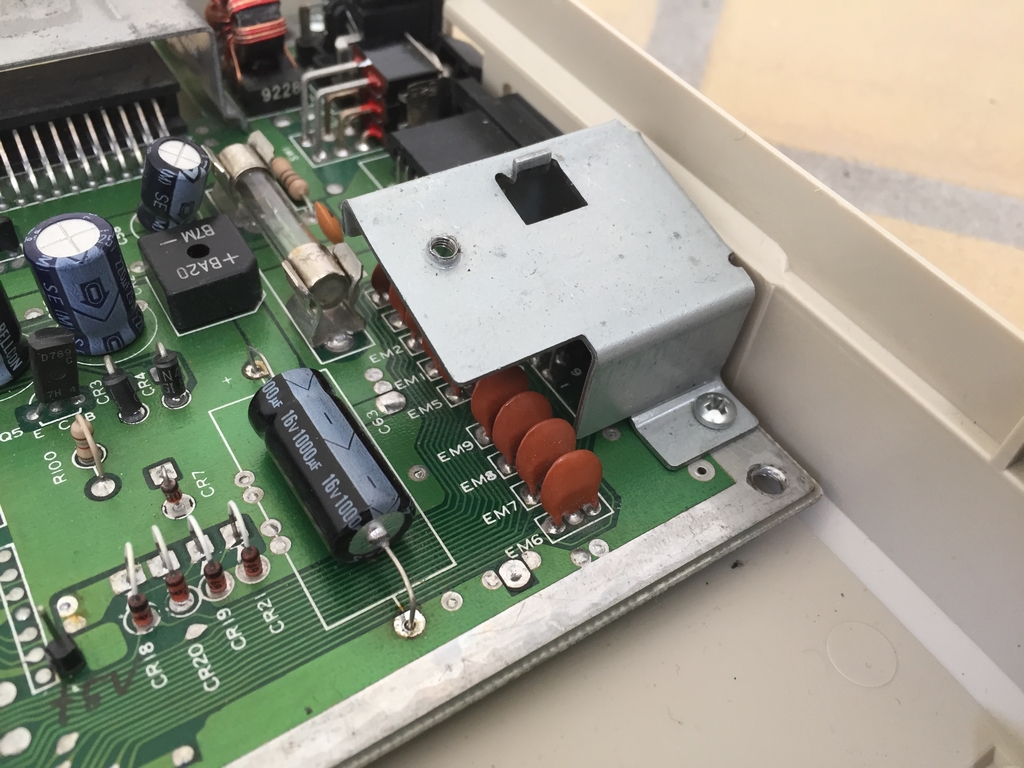
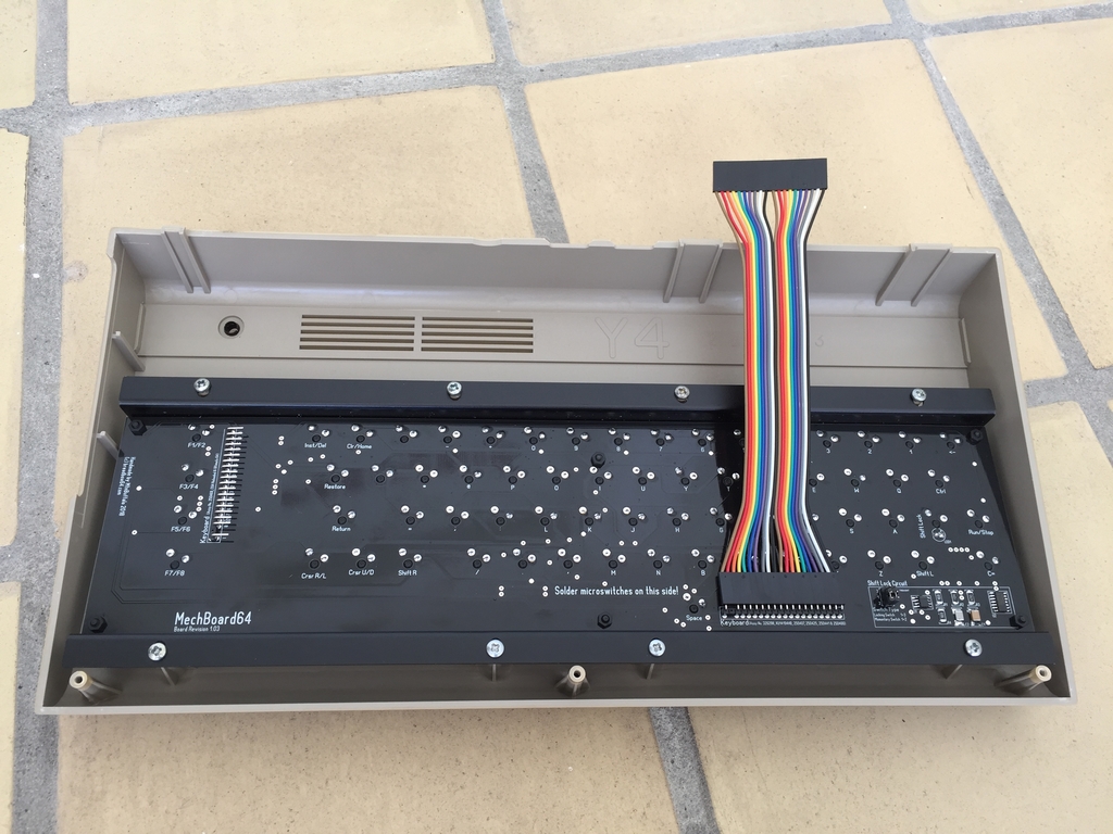
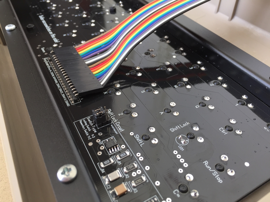
The PCB is black because I wanted it to have the same color as the C64 Reloaded boards. We want things to look nice, right? I had the PCBs made in 2 mm thickness to make them as sturdy as possible. This is overkill as all force during key presses will be on the aluminum bracket and not the PCB… At the bottom right side of the board is the Shift Lock circuit which handles the functionality of the Shift Lock key without using a locking type switch. The circuit is described in further details below.
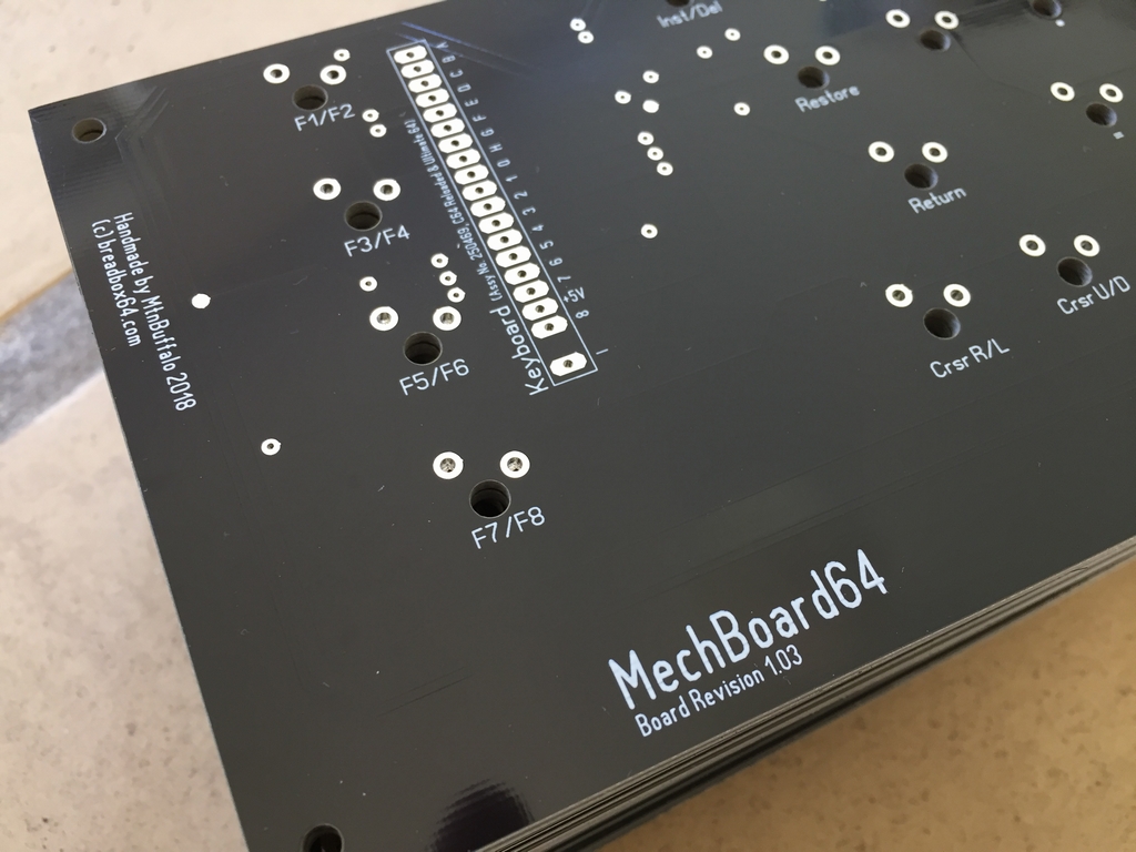
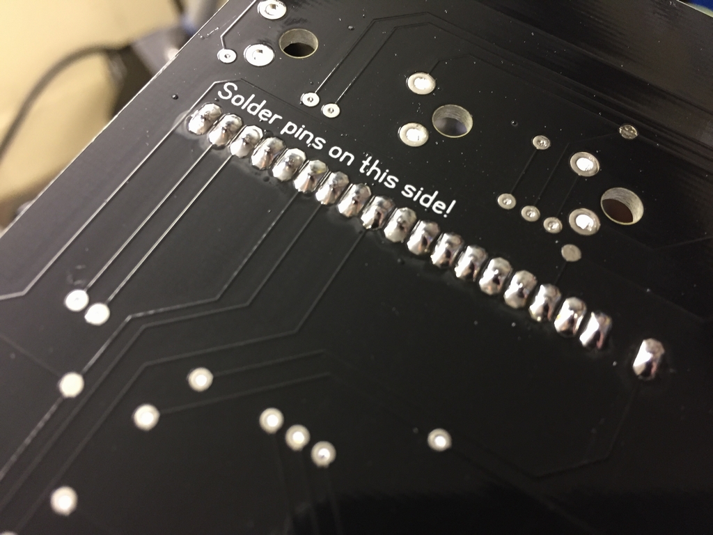
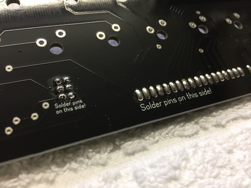
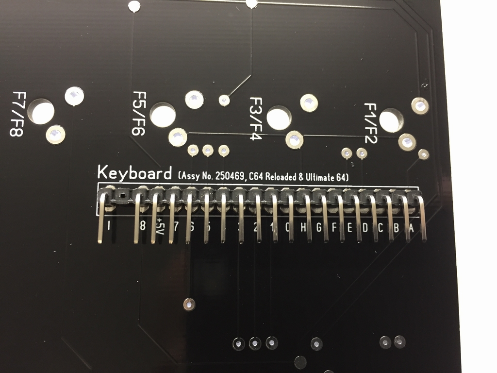
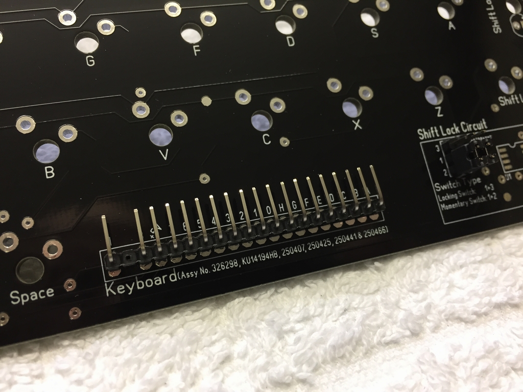
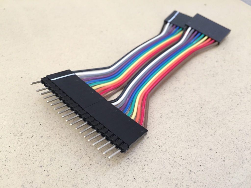
The PCB has two 20 pin angled male pins headers at each end of the PCB. A short 20 cm ribbon cable is used to connect hte MechBoard64 to the motherboard of the C64. Depending on the motherboard version I can simply use the pin header that is the closest to the socket on the C64. Text near the 20 pin header indicates what motherboard each pin header is best suited for…
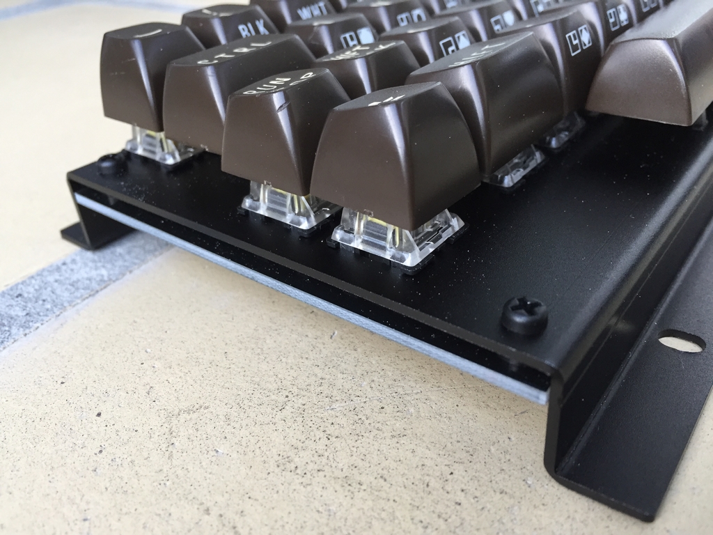
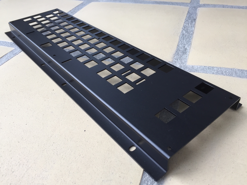
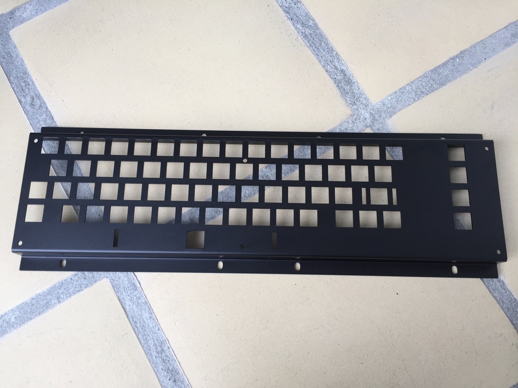
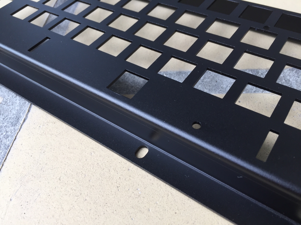
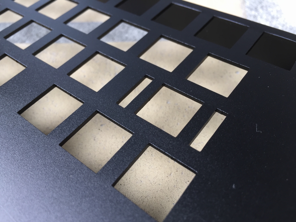
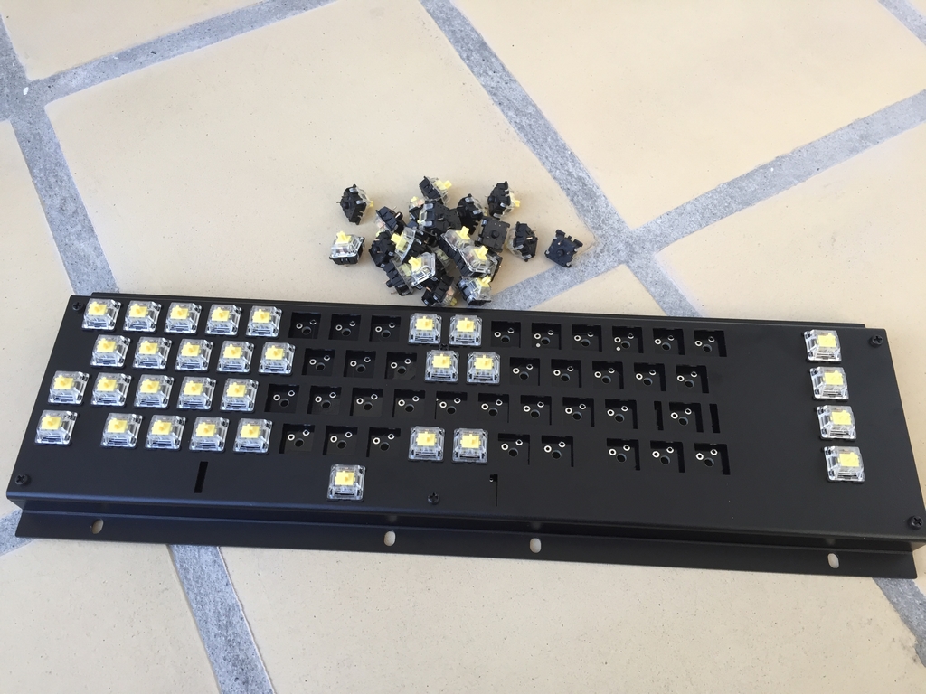
The Aluminum Bracket
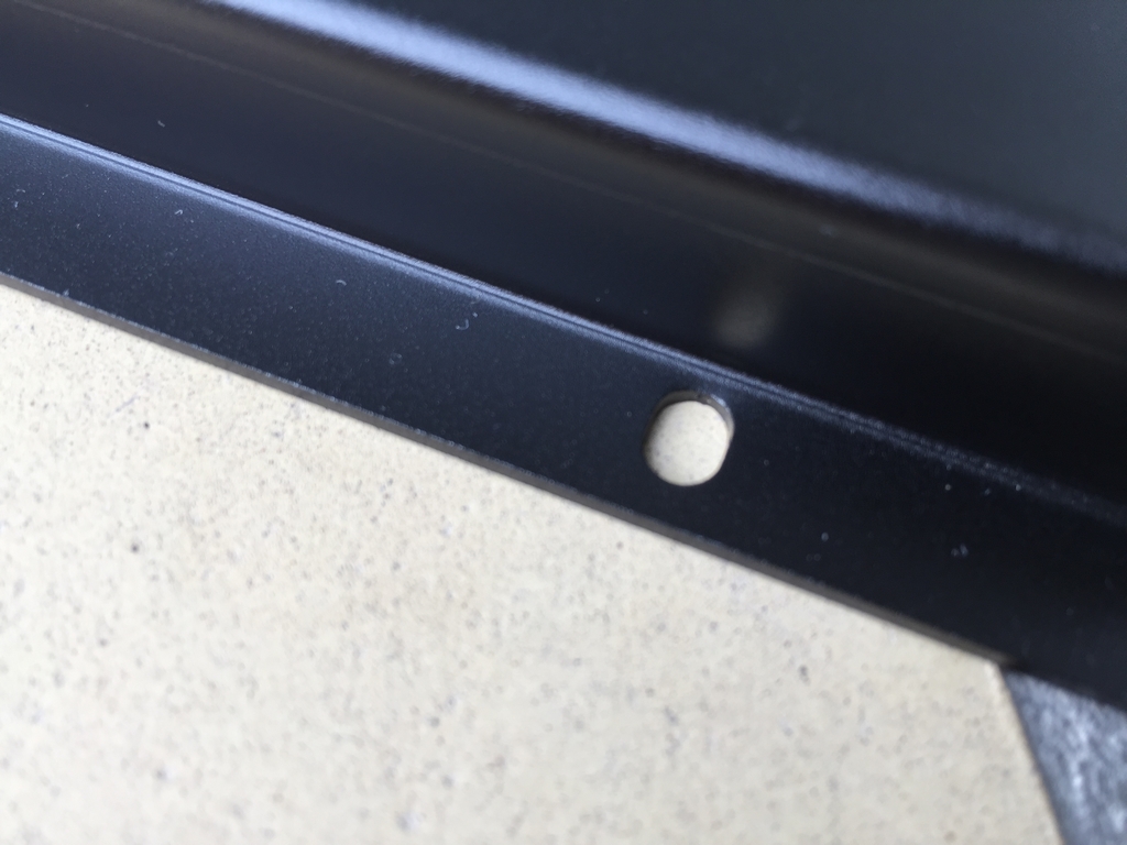
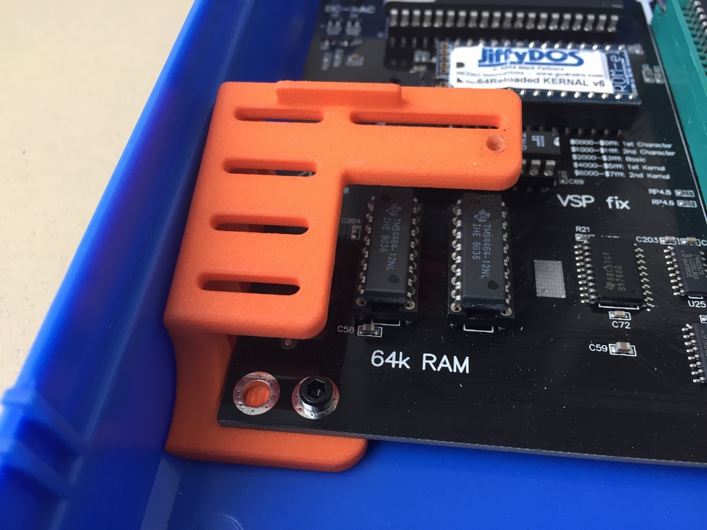
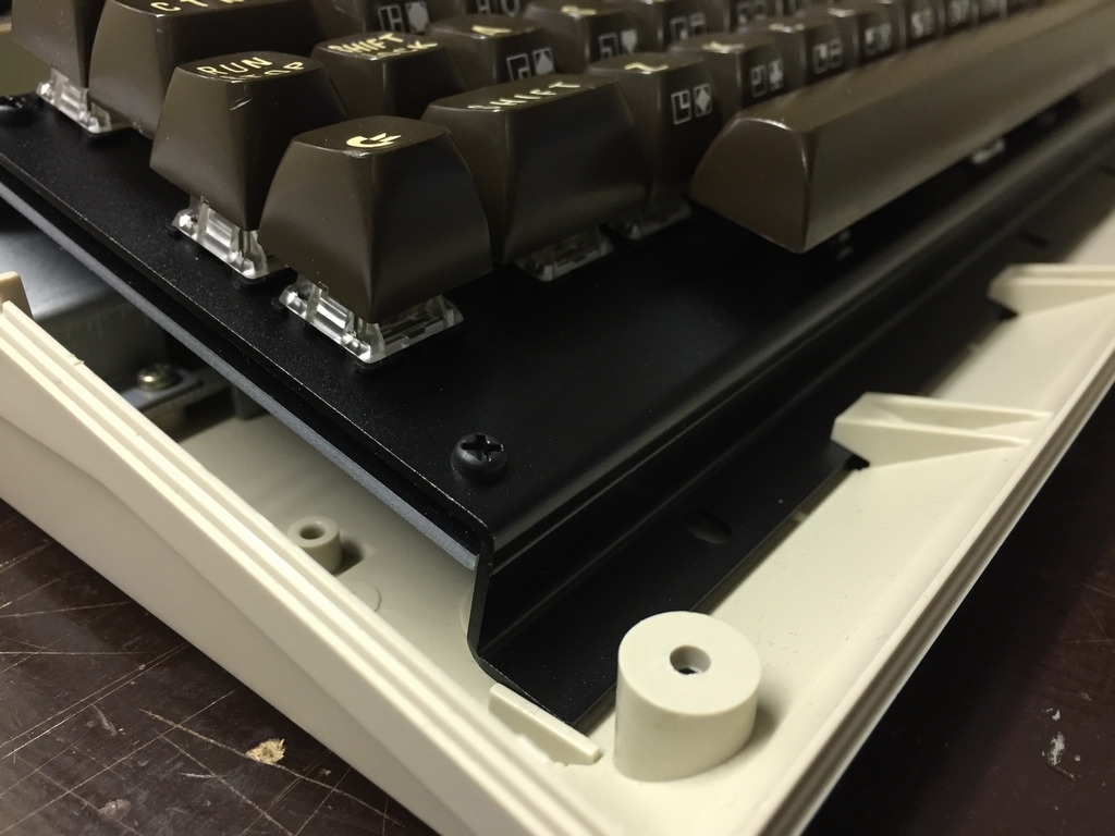
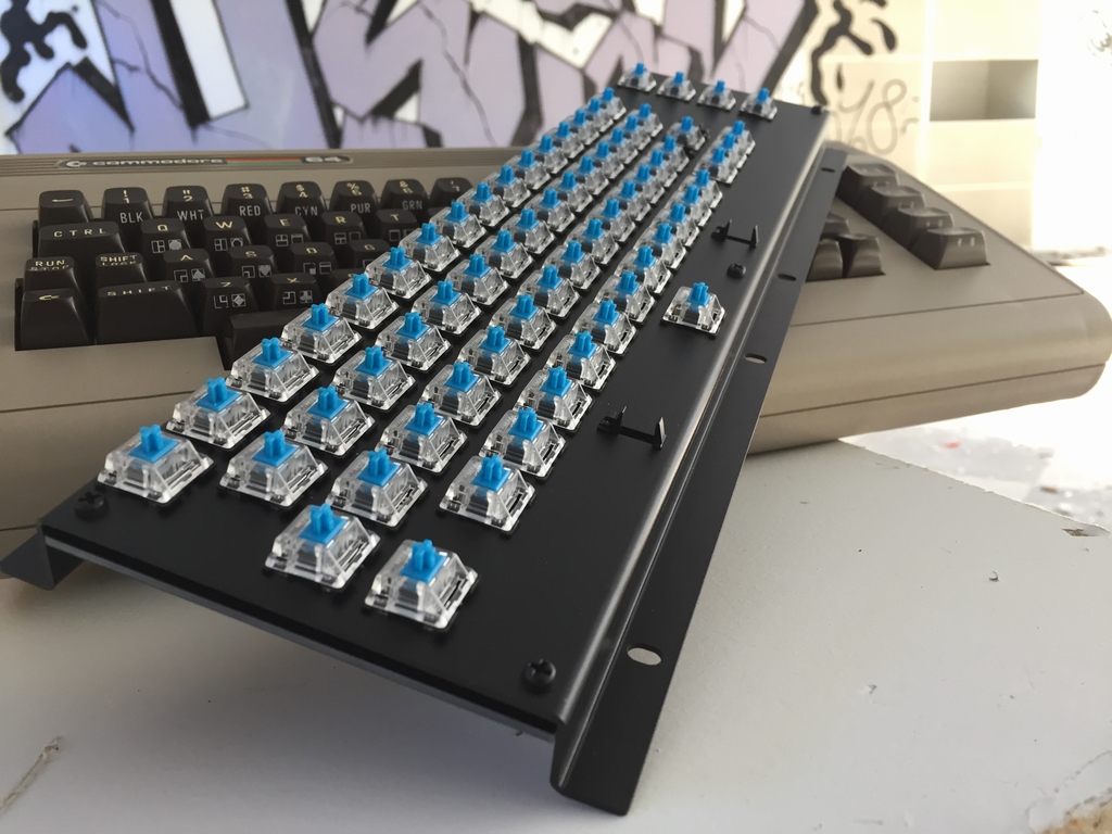
The first prototype had a bracket (the part holding the microswitches and the PCB) made of black acrylic plates (link). They had a thickness of 2 mm which is too thick for the Costar plate mounted clips, the microswitches and the C64C slim cases. These parts need 1.5 mm plates to snap into place correctly. The acrylic plastic is also very brittle and may break during normal use. I therefore completely redesigned the bracket using 1.5 mm black anodized aluminum which is way stronger and similar to modern high-end mechanical keyboards. The aluminum bracket is also a nice addition to the great looking C64 Reloaded and Ultimate64 boards! The aluminum brackets have been lasercut and bend by hand and they have submilimeter precision. The finish really exceeded my expectations and is almost too good looking considering that it will be hidden inside a case…
The holes for attaching the keyboard to the internals of the Commodore 64 have been slotted to make small adjustments possible during installation. To finish everything off, black nylon screws, black nylon spacers and black nylon nuts were used to attach the PCB to the aluminum bracket.
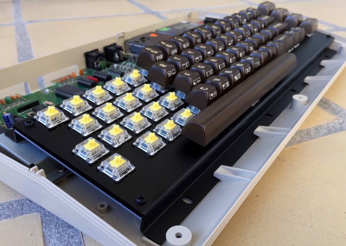
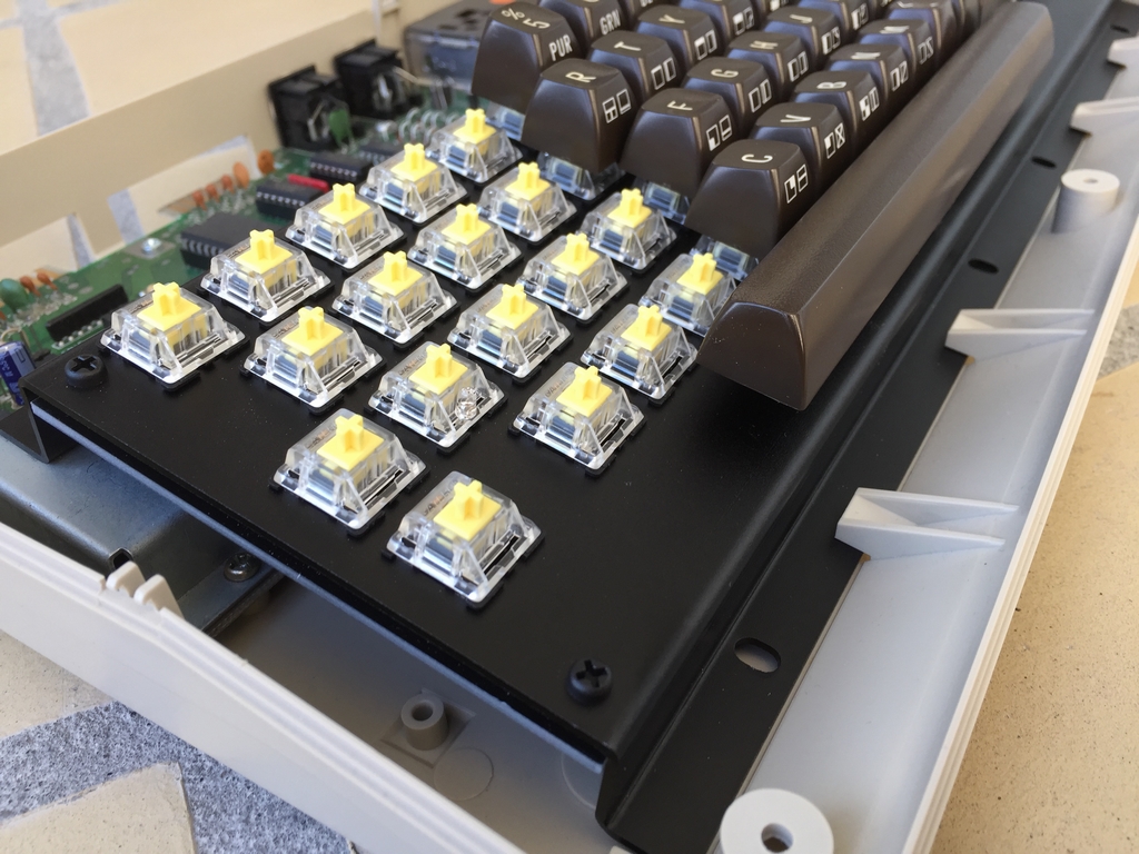
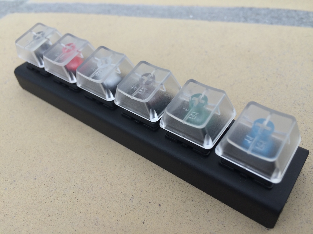
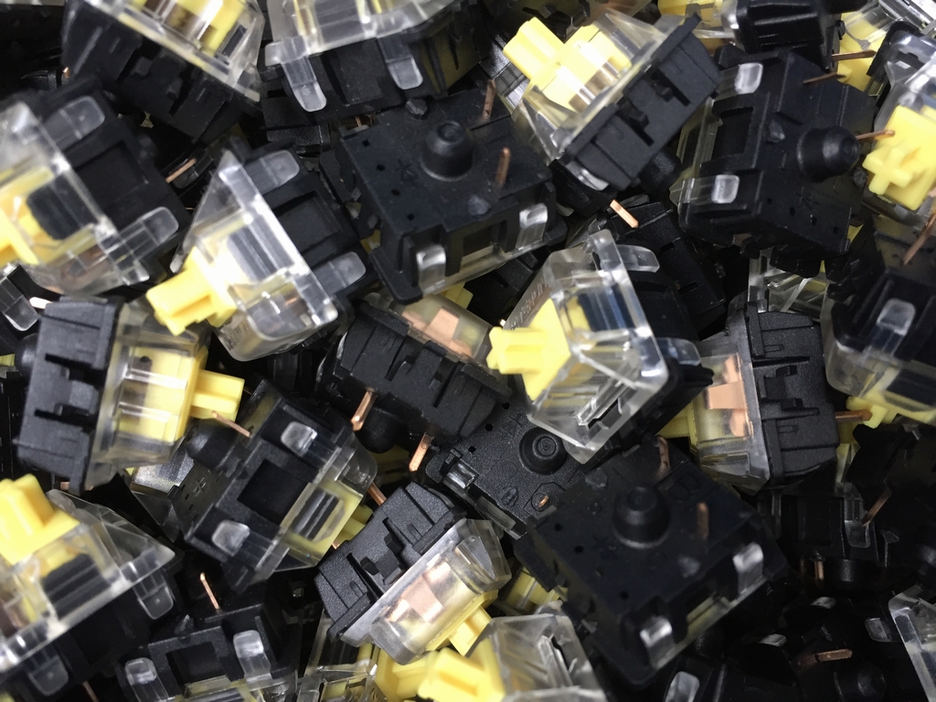
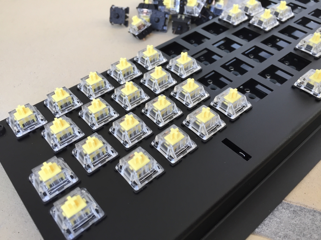
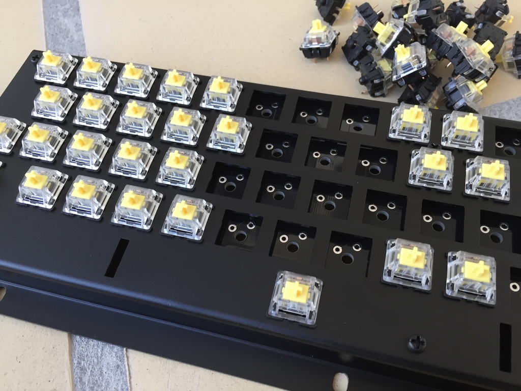
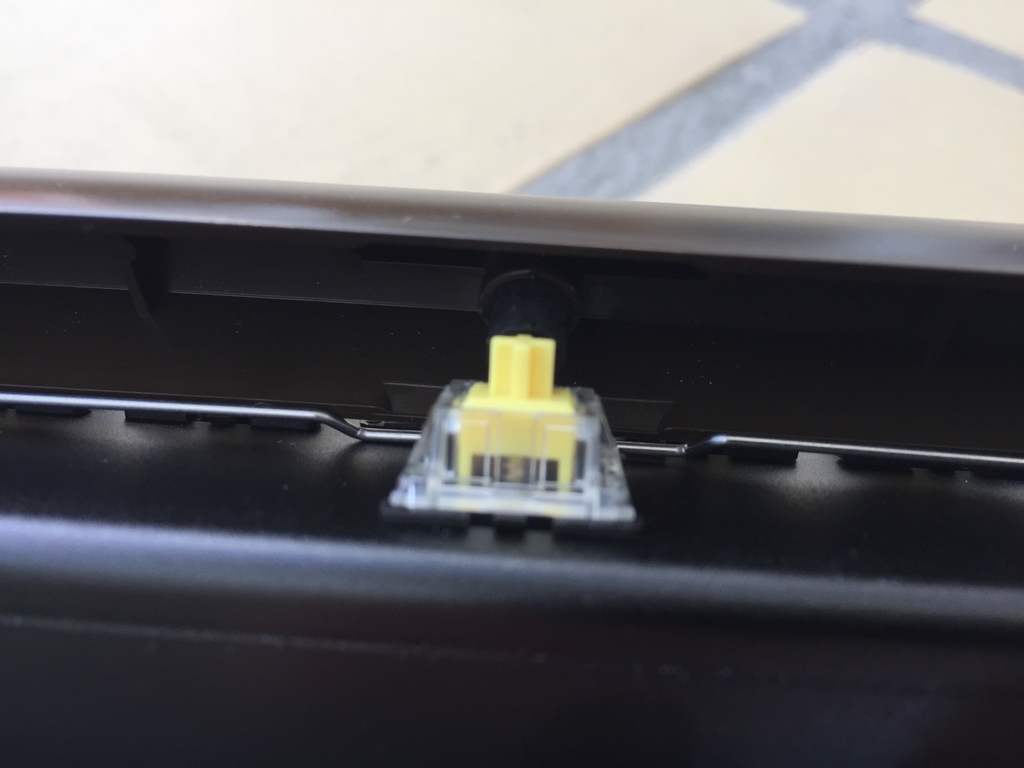
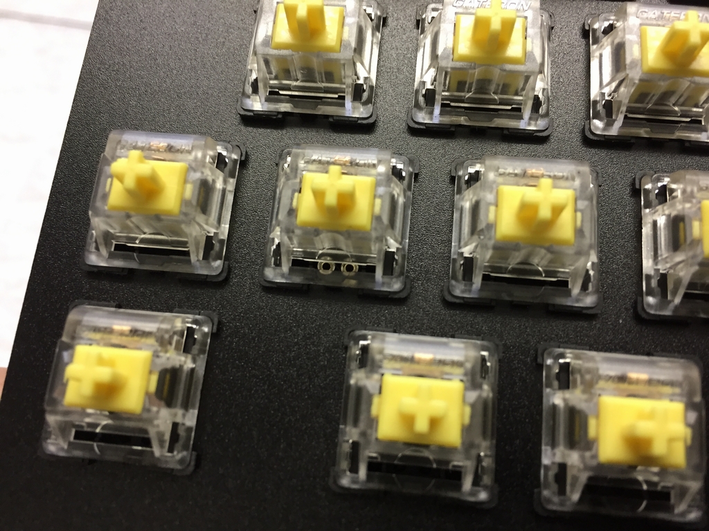
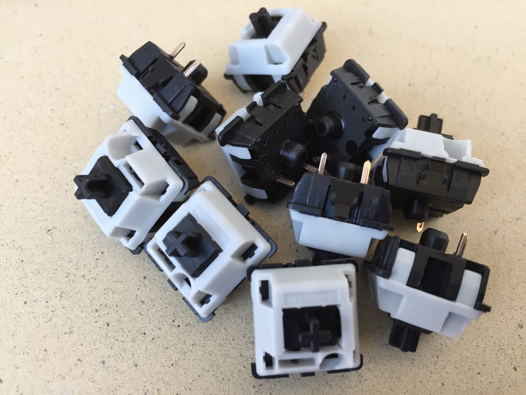
Microswitches
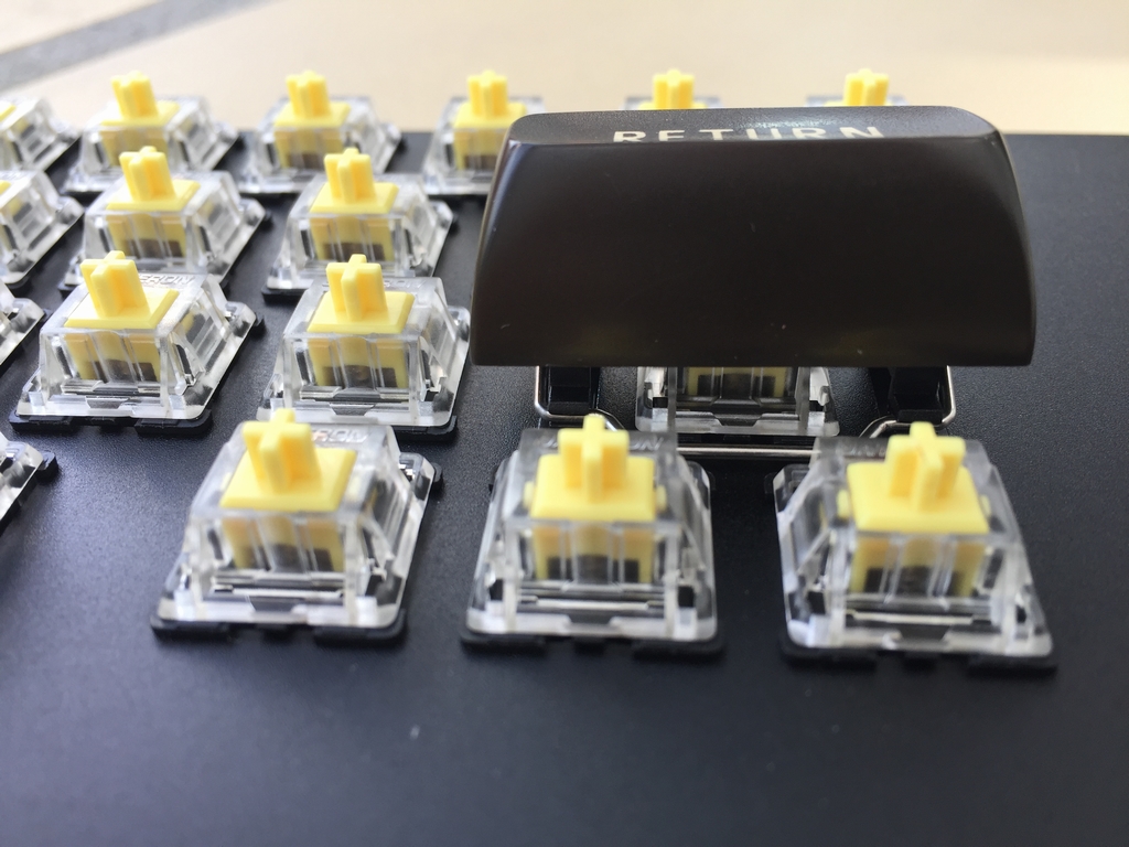
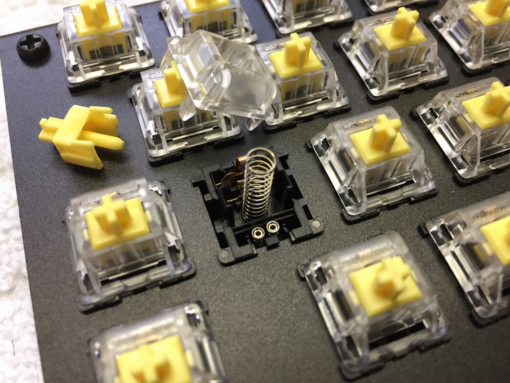
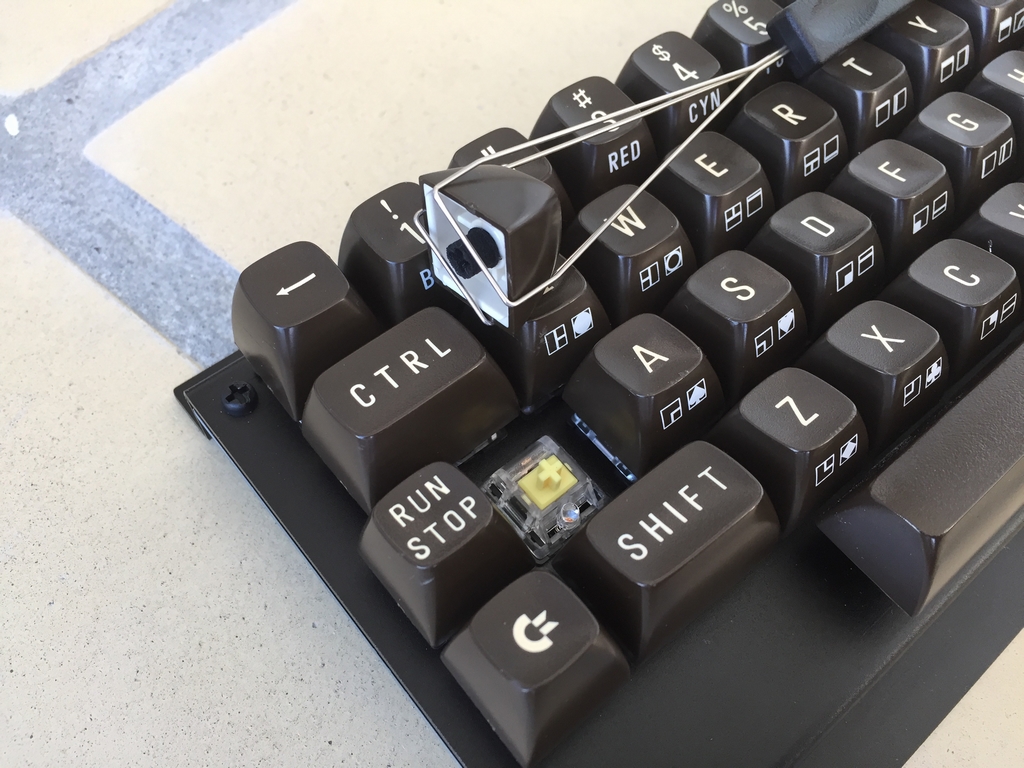
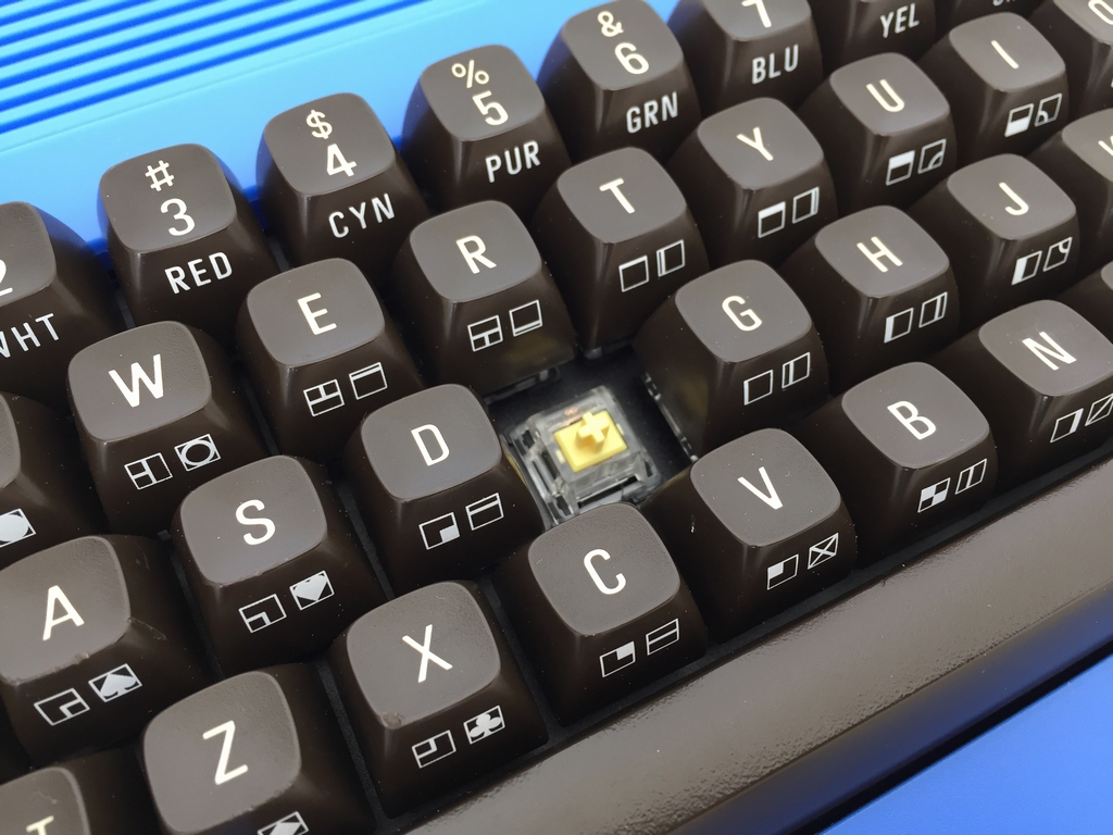
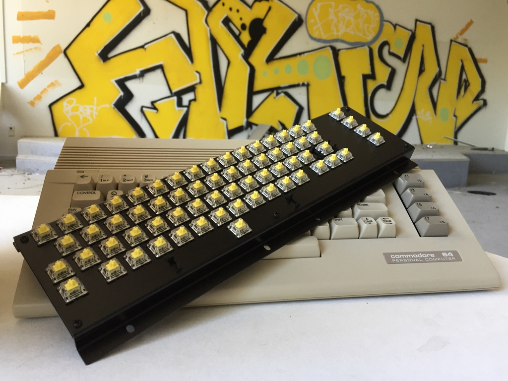
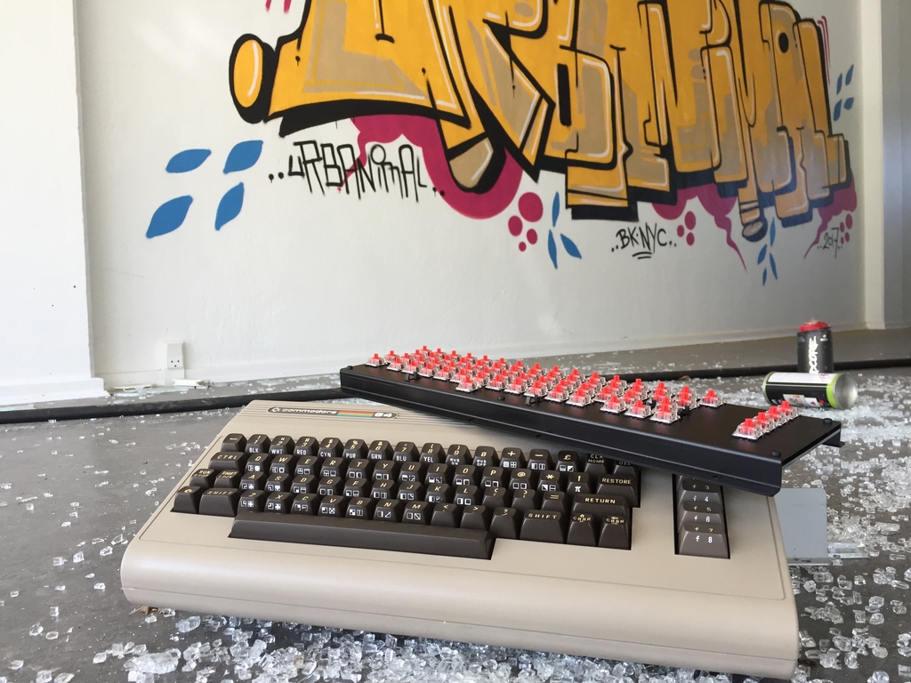
I spent quite some time on deciding what microswitch I wanted to use for the MechBoard64. However, I quickly decided to use microswitches from Cherry mx or Gateron as these seemed to be the most used in modern keyboards and would also be available in the future. To this end, each manufacturer has different types of switches (linear, clicky, tactile) that need different amount of force to activate. I therefore invested in a little microswitch testing board and ordered pretty much all the different flavours of Cherry mx and Gateron switches. The test board made it quite easy to test the different microswitches from both manufacturers at the same time while having an original C64 keyboard as reference. It quickly came clear that the Cherry mx reds (45 g linear) and Gateron yellows (55 g linear) resemble the original C64 keyboard the best. However, the Gateron switches have a smoother feel when pressing them and they are also almost half the price of the Cherry’s. Both manufacturers guarantee that their switches work for at least 50 million keypresses which should be more than enough for all my C64 typing needs! So my new keyboards both have Gateron yellows installed…
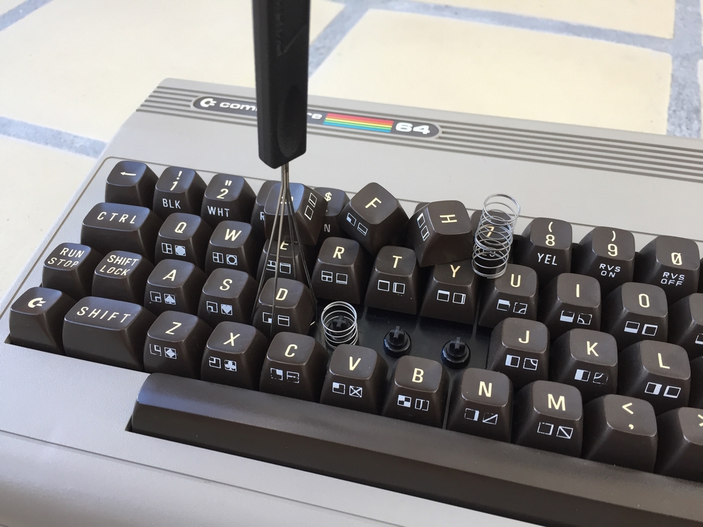
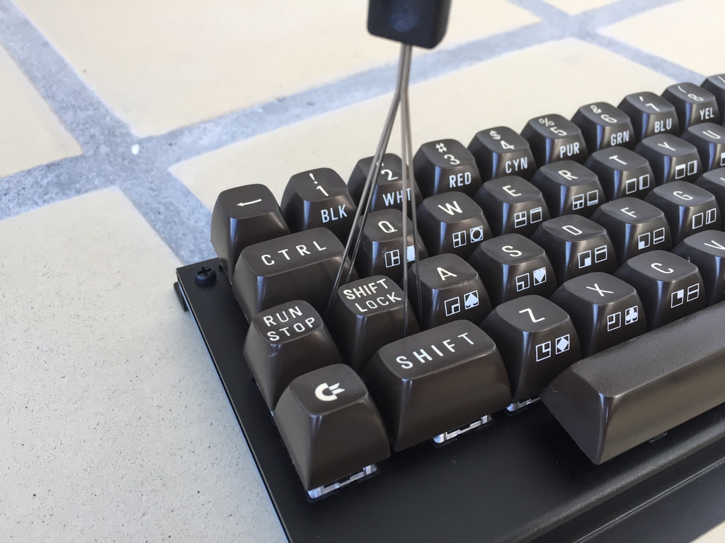
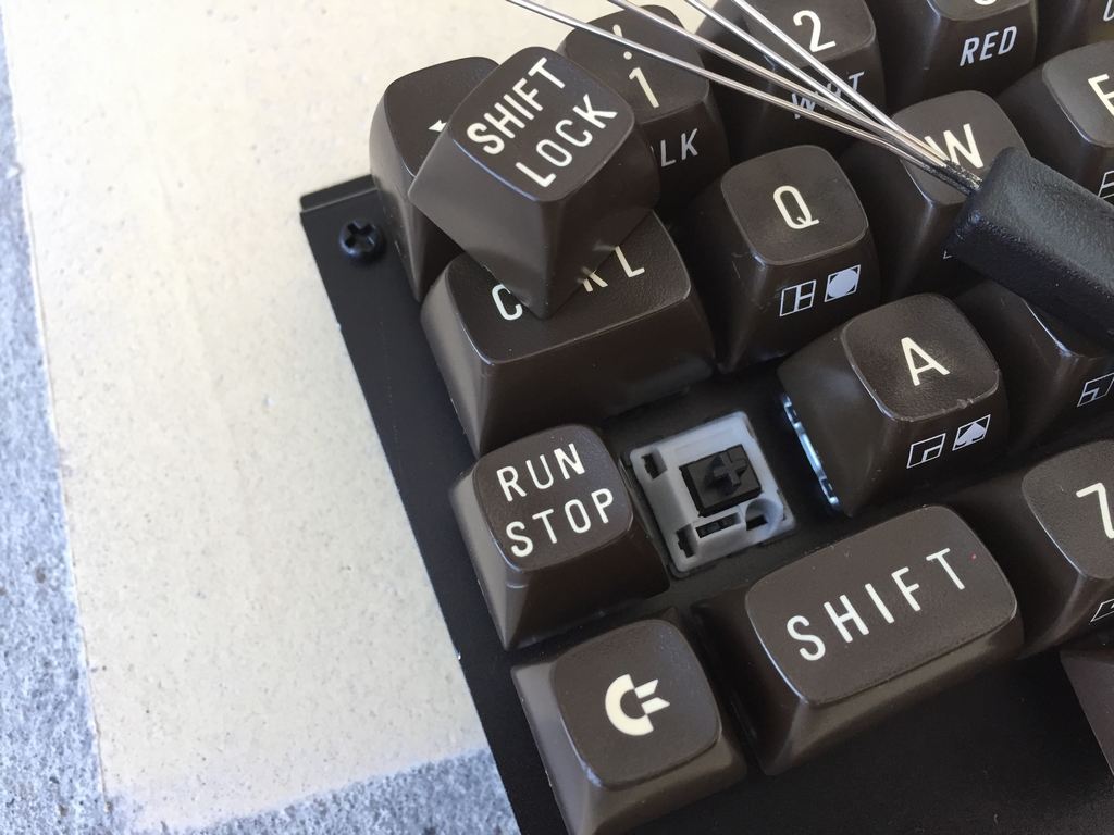
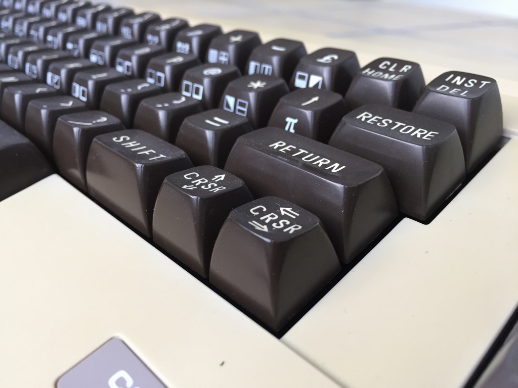
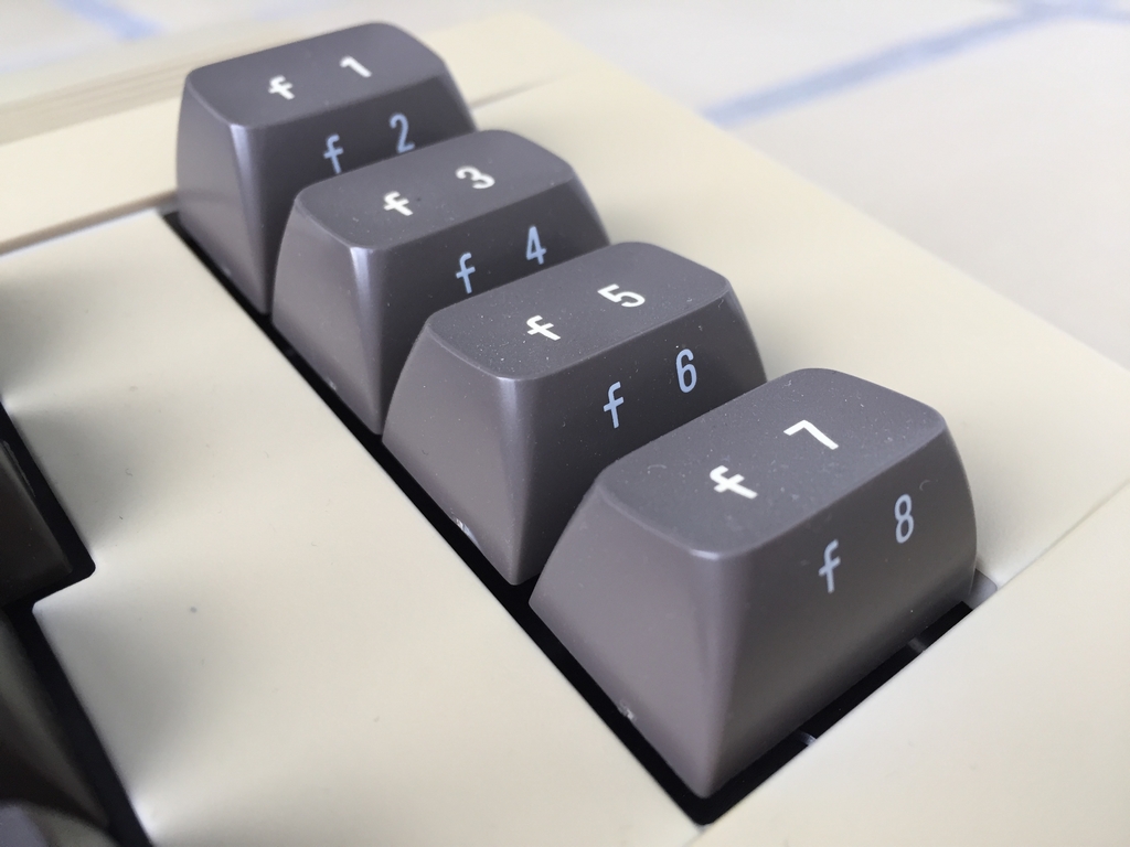
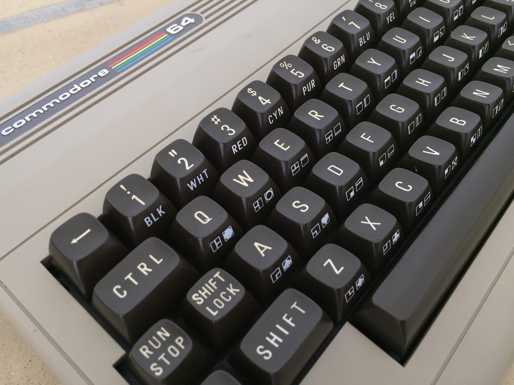
The keycaps were removed from donor keyboards of two original Commodore 64 breadboxes as I’m still waiting for the new keycaps from the Phase5/Indiegogo campaign to finish. Using a keycap puller made the job very easy and reduced the risk of breaking the fragile plastic pegs on the old C64 keyboards.
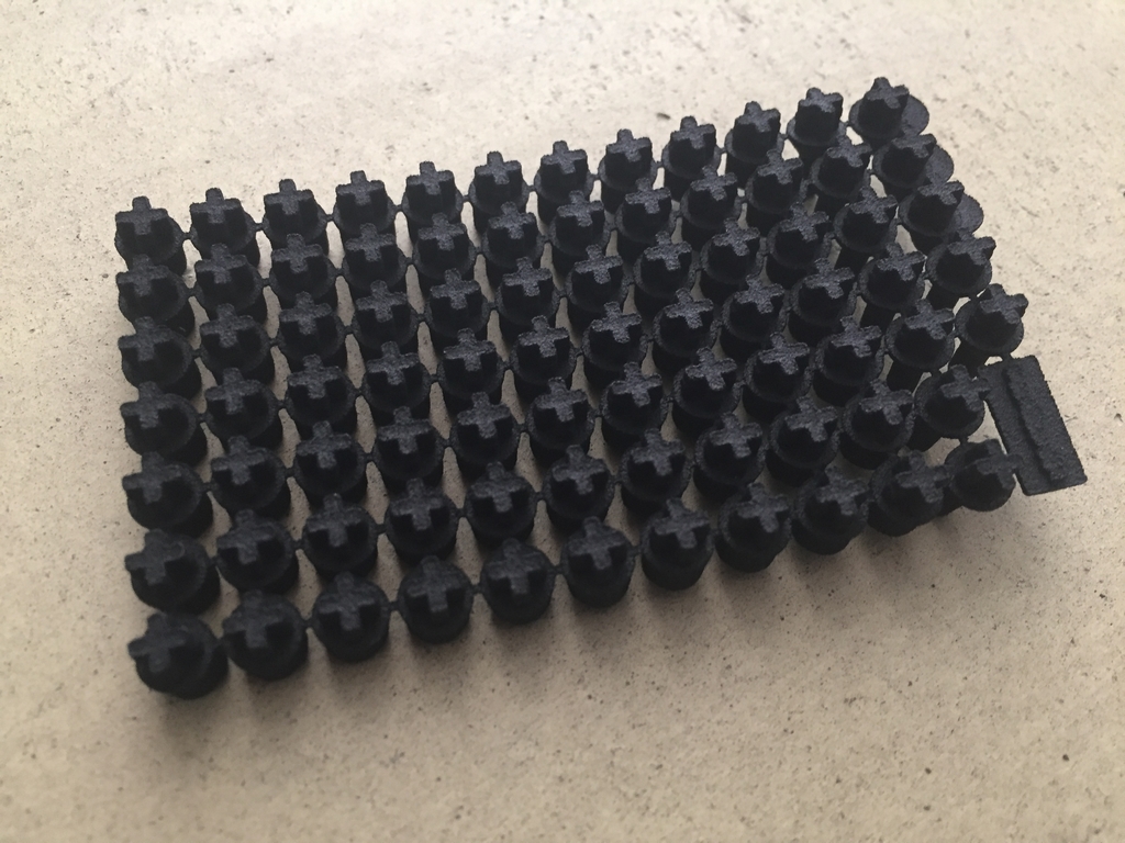
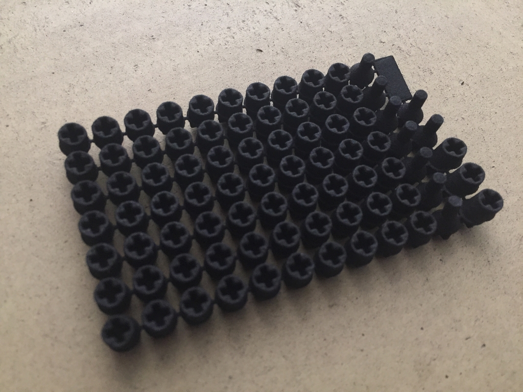
3D Printed Key Adapters
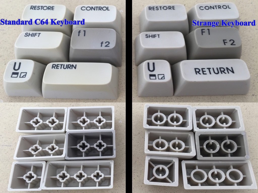
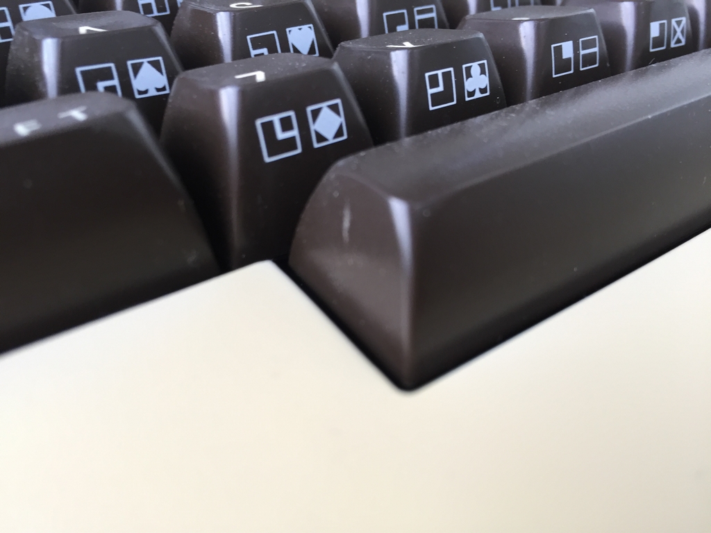
In order for the original C64 keycaps to fit the stems of the Gateron switches, 3D printed key adapters have to be used. A guy on Deskthority (link) made the CAD drawing and I’ve updated them slightly for an even better fit. The keycap adapters are made from Shapeways in a material called Strong and Flexible which is also known as Nylon Plastic, PA12 or Polyamide. They are printed using Selective Laser Sintering (SLS), which is strong enough for structural components. The 3D prints fits really well and are easy to attach to the stems of the microswitches. The same goes for attaching the keycaps on top of the adapters. It is important to note that the 3D printed key adapters only work with the Cherry mx style switches (e.g. Gateron) and the standard Commodore 64 keycaps. Other C64 keycaps, like the ‘strange’ ones shown below, will not work and hence cannot be used with the 3D printed key adapters!
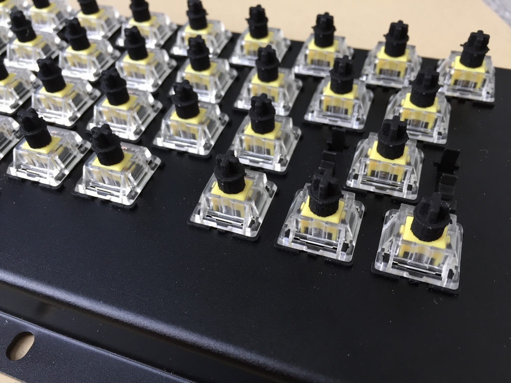
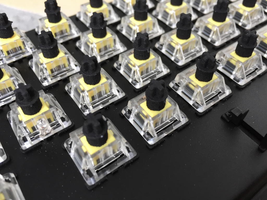
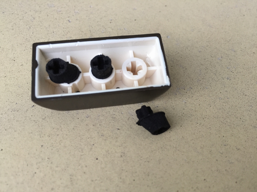
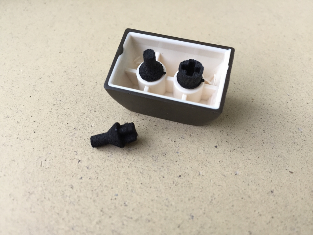
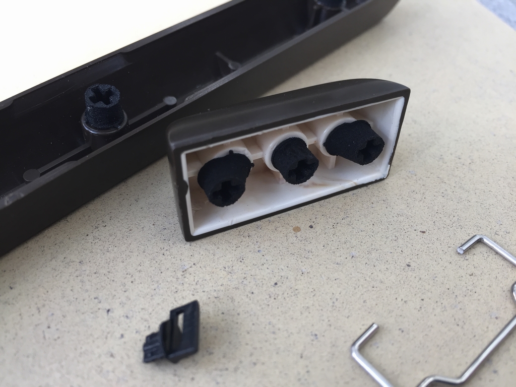
Special shaped adapters are used for the stabilizer wire of the Return key. All 1.5u sized keys (Shift keys, Function keys, Restore and CTRL) have a 3D printed stem installed into the free hole to stabilize the keys during key presses. The stabilizer system of the Spacebar simply uses the same 3D printed key adapters for the Costar keycap inserts.
Keyboard Stabilizers
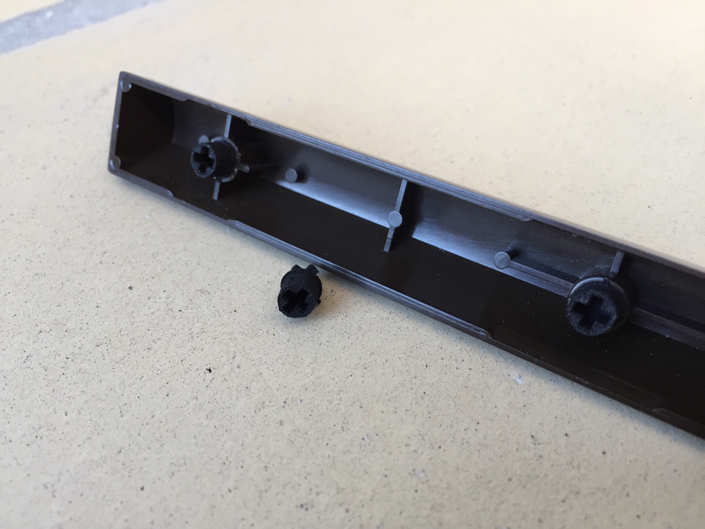
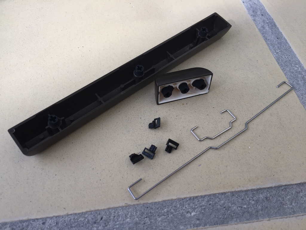
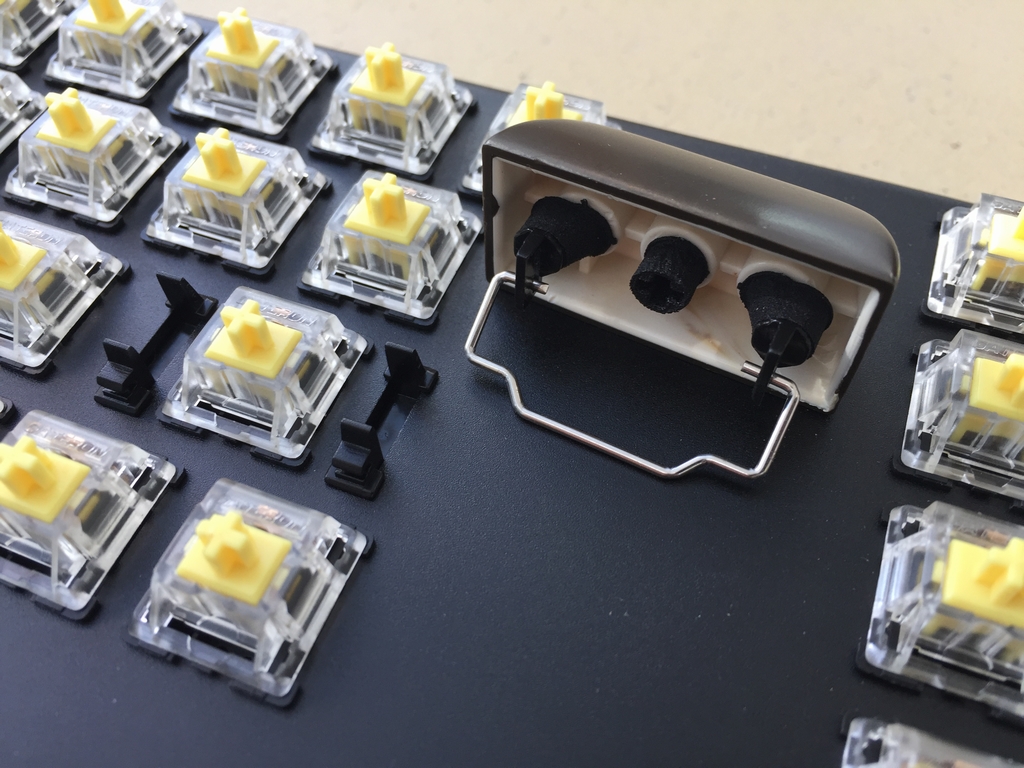
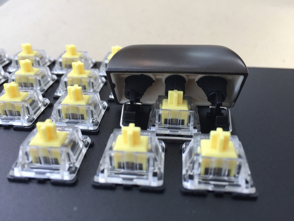
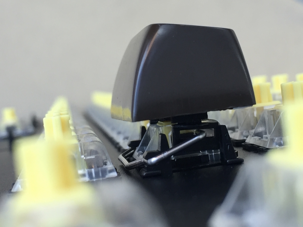
The Spacebar and Return keys both have a stabilizing wire installed underneath to keep them stable regardless of where they are pressed during use. Costar plate clips were snapped into the rectangular slots near the two keys while stabilizer wire were added to the Return key and Spacebar keys. I installed the two keys before anything else in order to have as much room as possible for fiddling everything into place.
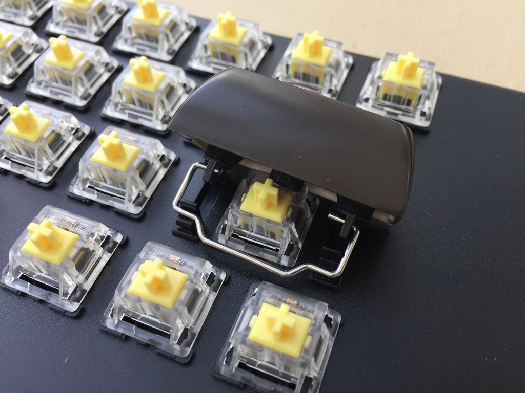
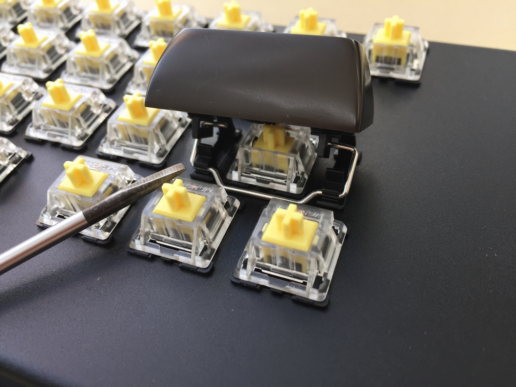
The Spacebar stabilizer wire is placed behind the spacebar in order to get as far away from the edge of the bracket as possible. This was to ensure that the bending tools did not alter the dimension of the slots. I used a flat headed screwdriver to gently push the mircoswitch stem down in order to attach the spacarbar.
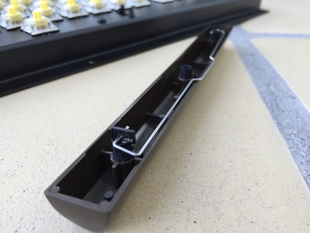
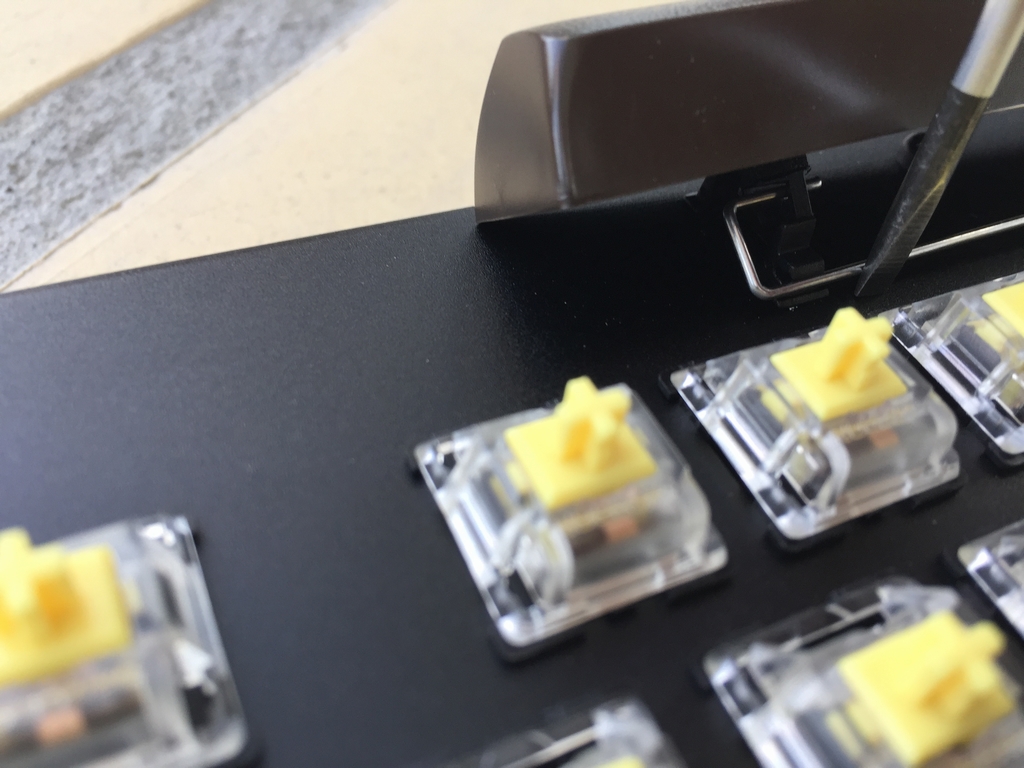
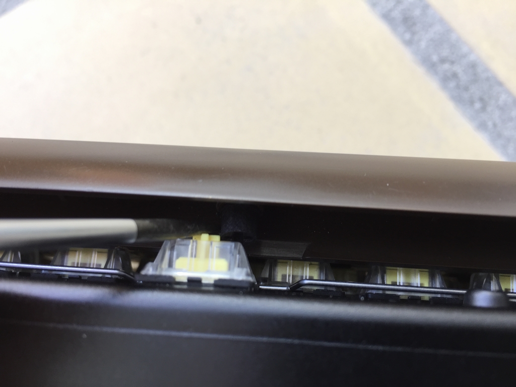
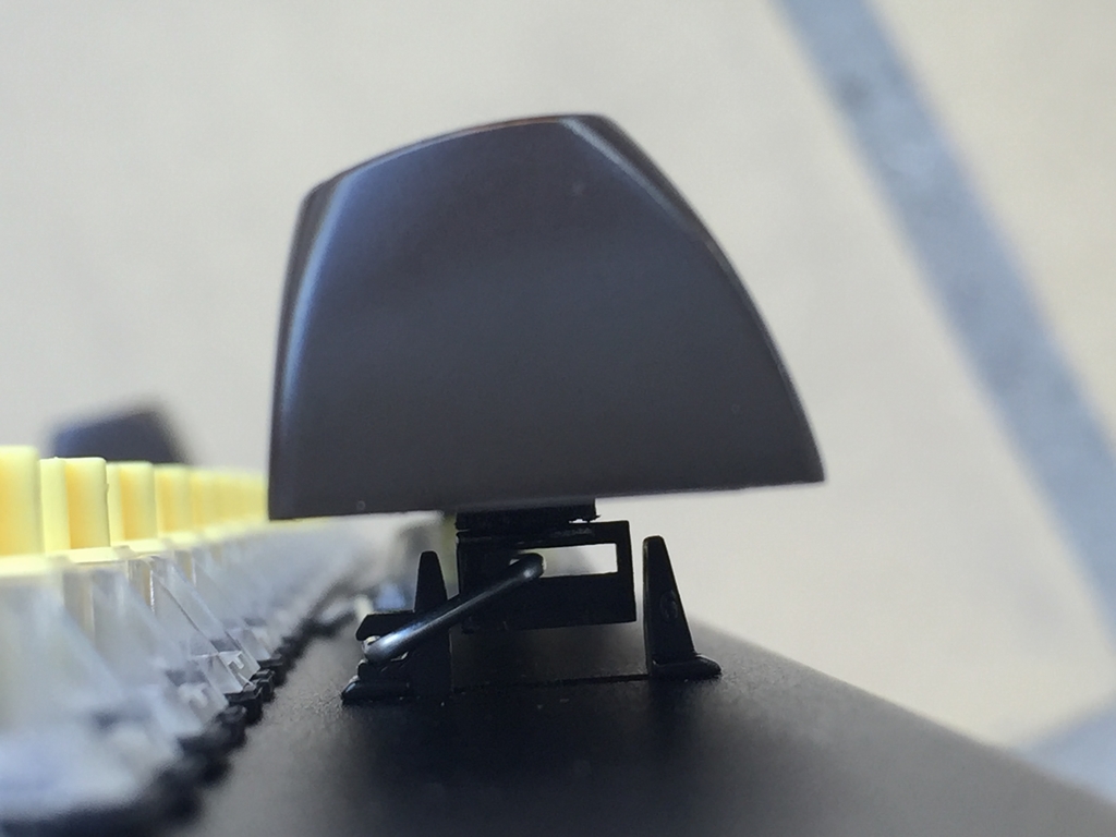
I then installed the Return key. First the stabilizer wire was installed into the Costar keycap inserts before snapping it into the two plate mounted inserts. Again, a flat headed screwdriver was used for snapping everything into place.
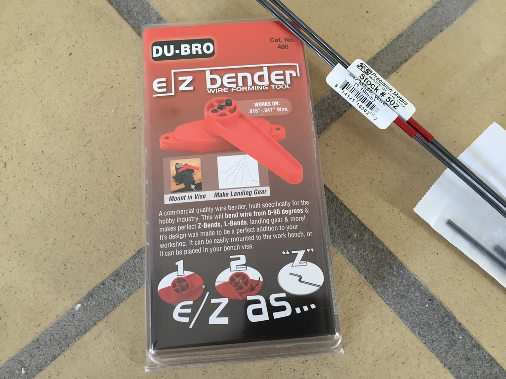
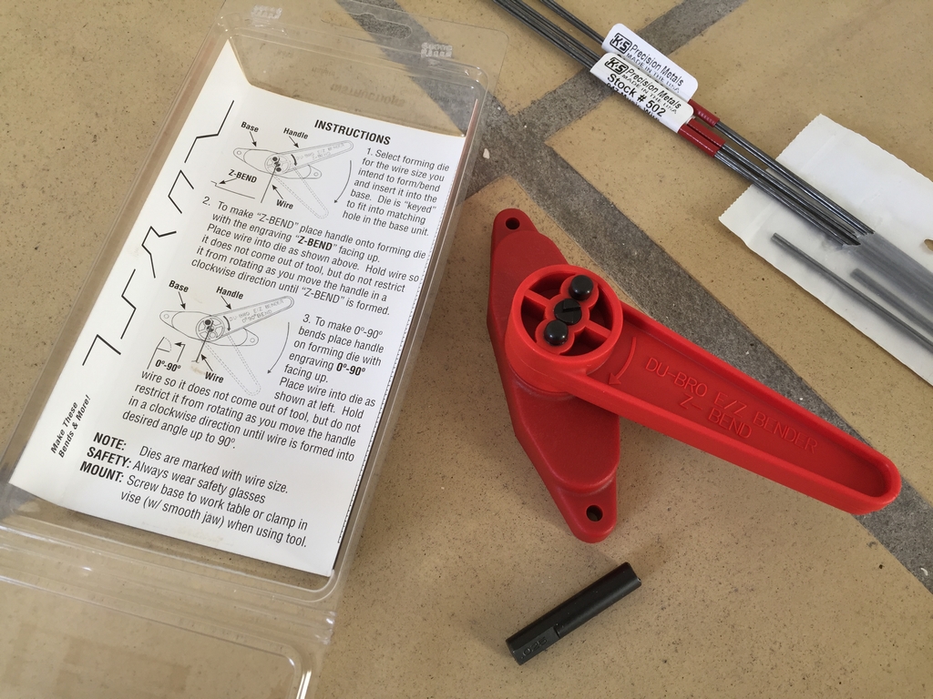
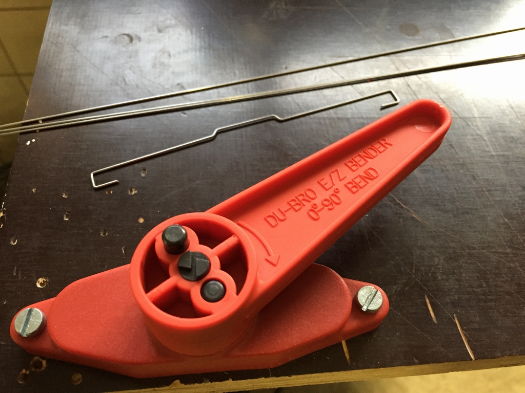
I had to make my own stabilizers as the size of the SpaceBar is very long (size 9u!). I used a tool called DuBro EZ Bender #480 and some piano wire. Before I even had the first stabilizer made, I broke the die… typical, right? I also found that the 1.19mm wire was a bit too thick for the costar keycap inserts. After replacing the broken die, I got some thinner 1.00 mm piano wire and after that, making the stabilizers went pretty fast.
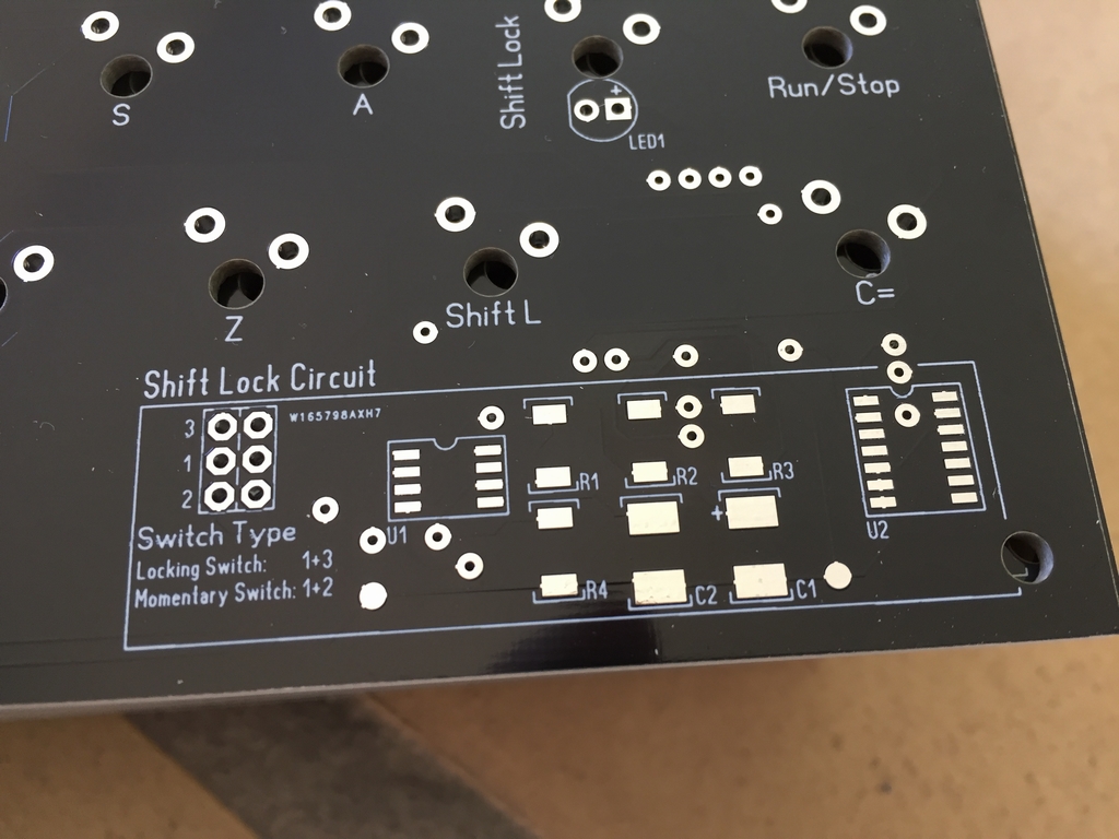
Shift Lock Circuit
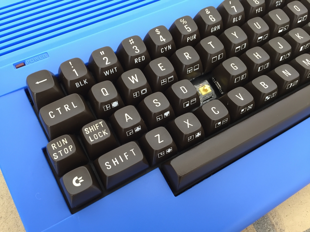
The original Shift Lock key uses a latching/locking type switch. Cherry used to make these but have since discontinued making them. Thus, I had to come up with another solution. I therefore made a small circuit which adds a push on push off functionality. This way a standard non-latching microswitch can be used to turn on the Shift Lock and when pressed again, turn it off. In order to get a visual indication of the state of the switch (on or off) a red 3 mm LED is placed underneath the keycap which lights up whenever the switch is activated. The circuit is made from a few standard components including a NE555 timer, a 4066 analog switch, some resistors and two capacitors.
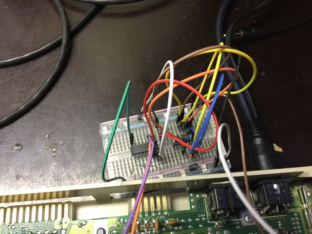
Before transferring the circuit onto the PCB, the Shift Lock circuit was tested with a simple breadboard connected to a Commodore 64. The Shift Lock circuit is powered using the 5V line going to the keyboard. This 5V line is not used on the original C64 keyboards, so it came in handy for powering the Shift Lock circuit on my keyboards. The 5V line is also present on the C64 Reloaded boards and Gideon has confirmed that it is also present on his Ultimate64 boards (thanks Gideon!).
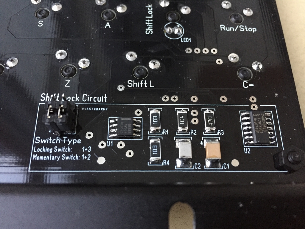
Two SIP sockets have been added to the Shift Lock microswitch. This way the color of the 3mm LED can easily be exchanged to match the color of the power LED of the machine.
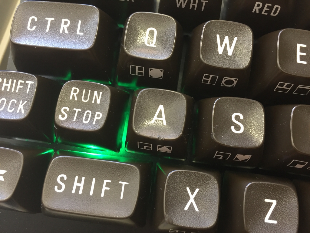
It is also possible to exchange the standard non-latching microswitch with a locking type switch like the Cherry Locking switch. To do this, the momentary microswitch obviously needs to be de-soldered and replaced. In that case the small Shift Lock circuit is no longer needed and must be bypassed in order for the locking switch to work properly. This is simply done by moving the two header caps inside the Shift Lock Circuit area of the PCB as indicated by the text on the board. Easy peasy!
NOTE: Using the MechBoard64 with a Keyrah from Individual Computers (link) should be possible. However, as the 5V line of the Keyrah is not connected, neither the Shift Lock circuit nor the LED will function. In this case, a Cherry Locking switch may be used instead.
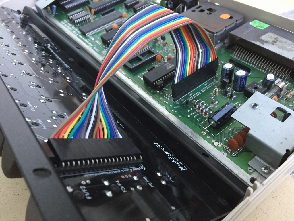
Wiring the MechBoard64
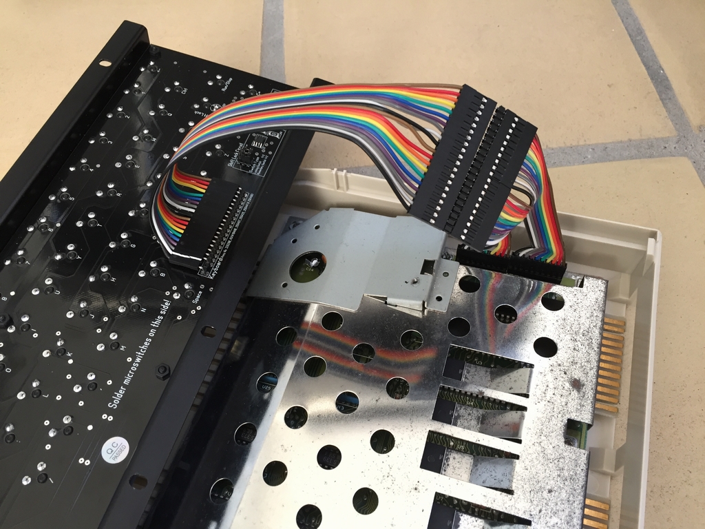
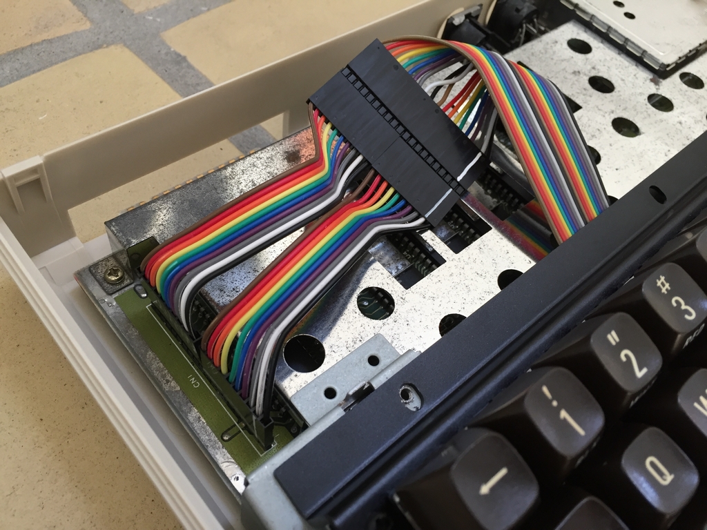
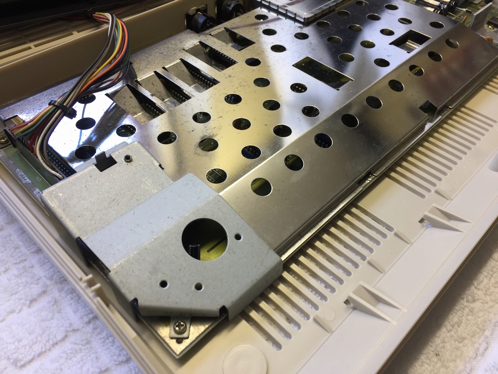
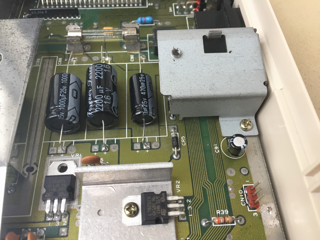
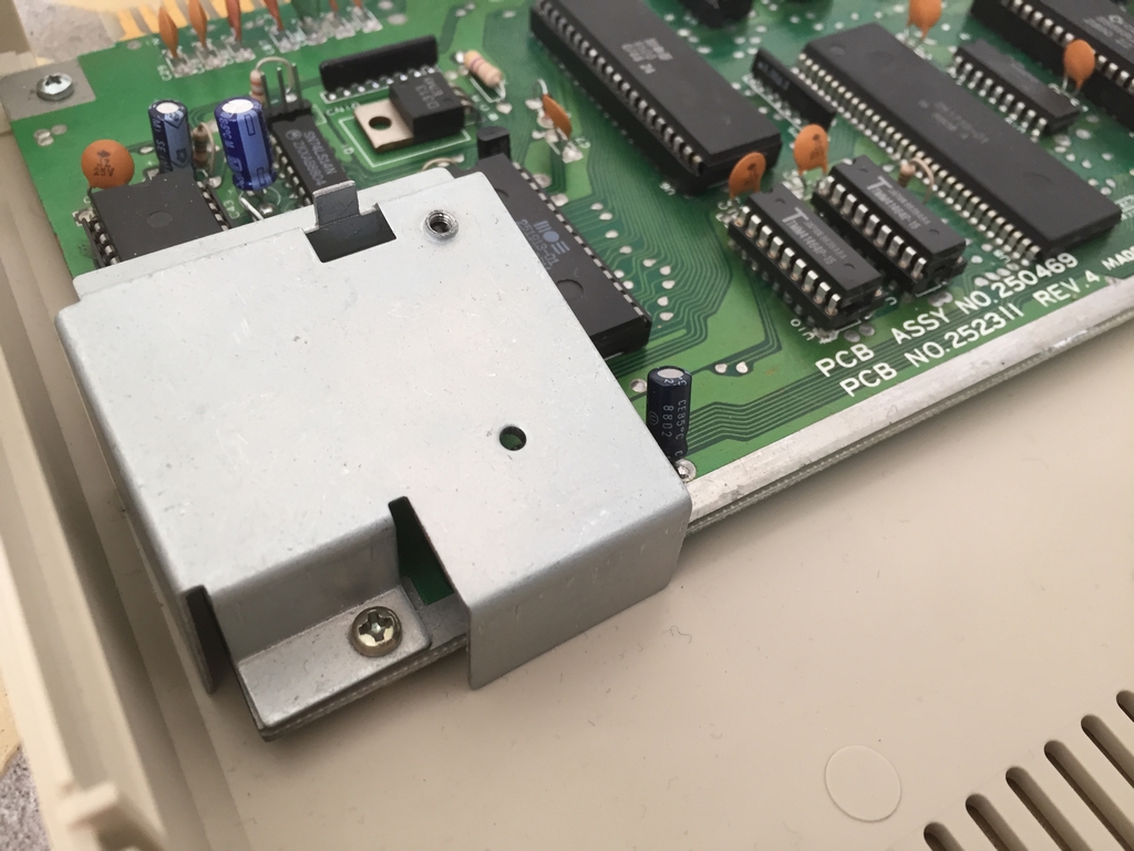
The keyboard is connected to the motherboard using a 20 cm ribbon cable. Below are images from installation in a long board (Assy 250425) and a short board (Assy 250469).
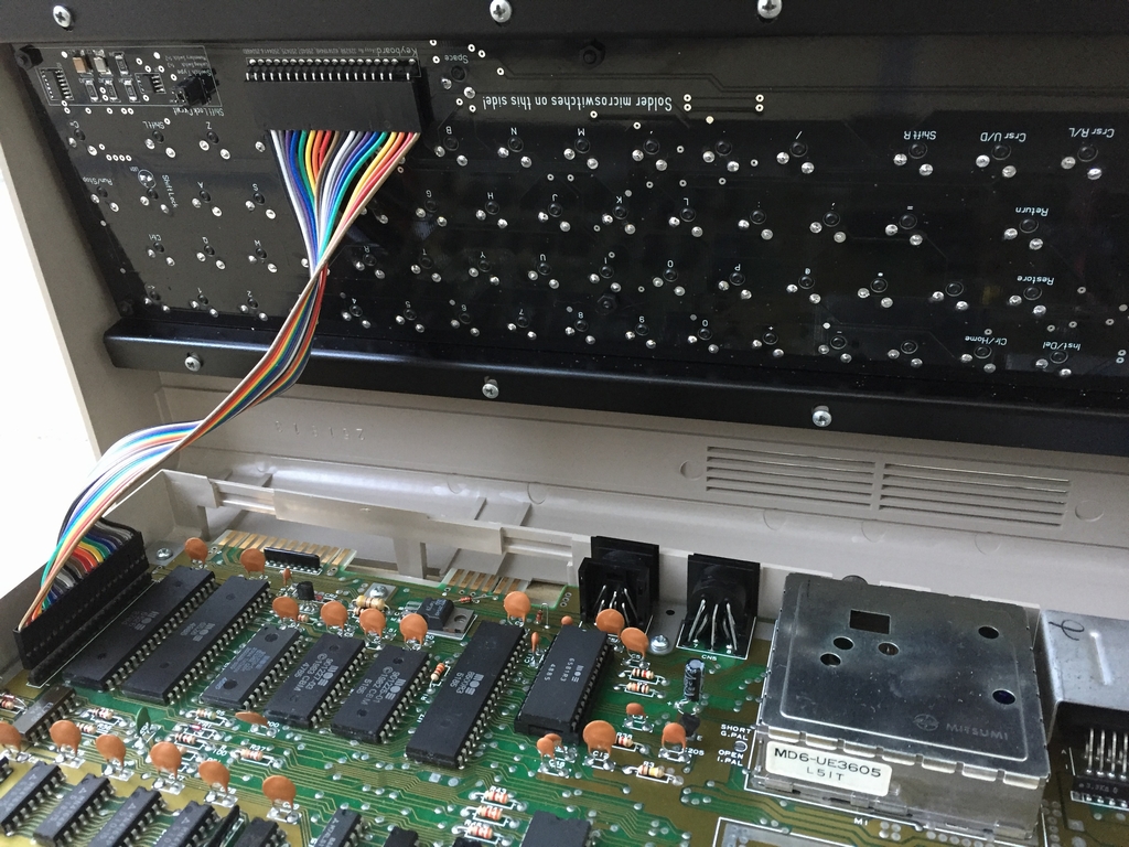
One of my C64C slim cases has an Assy 250466 long board installed as Commodore basically assembled machines depending on what they had in stock. The combination of a long board and a C64C slim case places the keyboard pins on the C64 motherboard quite far from the keyboard pins on the PCB and the 20 cm ribbon cable is simply too short. I therefore had to use a 10 cm extension cable to make it work. I have also seen Assy 250425 long boards installed in C64C slim cases. That combination will also need an extension cable…
Keyboard Case & Mount Compatibility
I wanted to make sure that the keyboard is as universal as possible. I therefore tested it in all the different machines that I have in my possession. I found that the MechBoard64 fits perfectly in all of my machines regardless of the internal hardware and cases (breadbox and C64C slim cases). The only combination that caused some trouble was long boards (e.g. Assy 250425 and Assy 250466) installed in a C64C slim case. This combination needs a longer ribbon cable in order to make the connection as described previously!
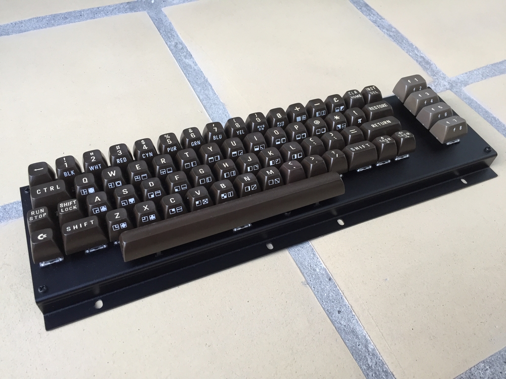
Adding the MechBoard64 to Real Hardware
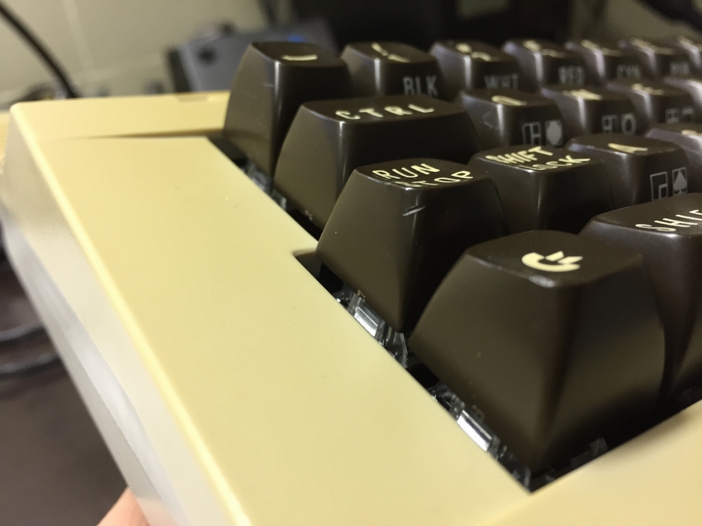
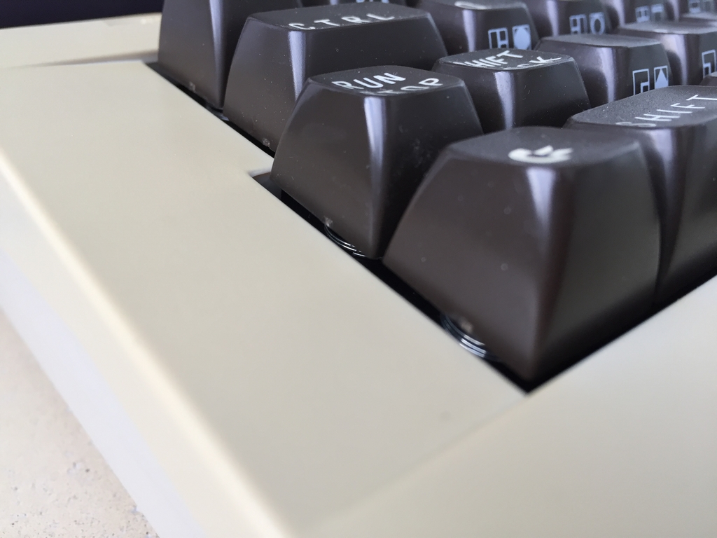
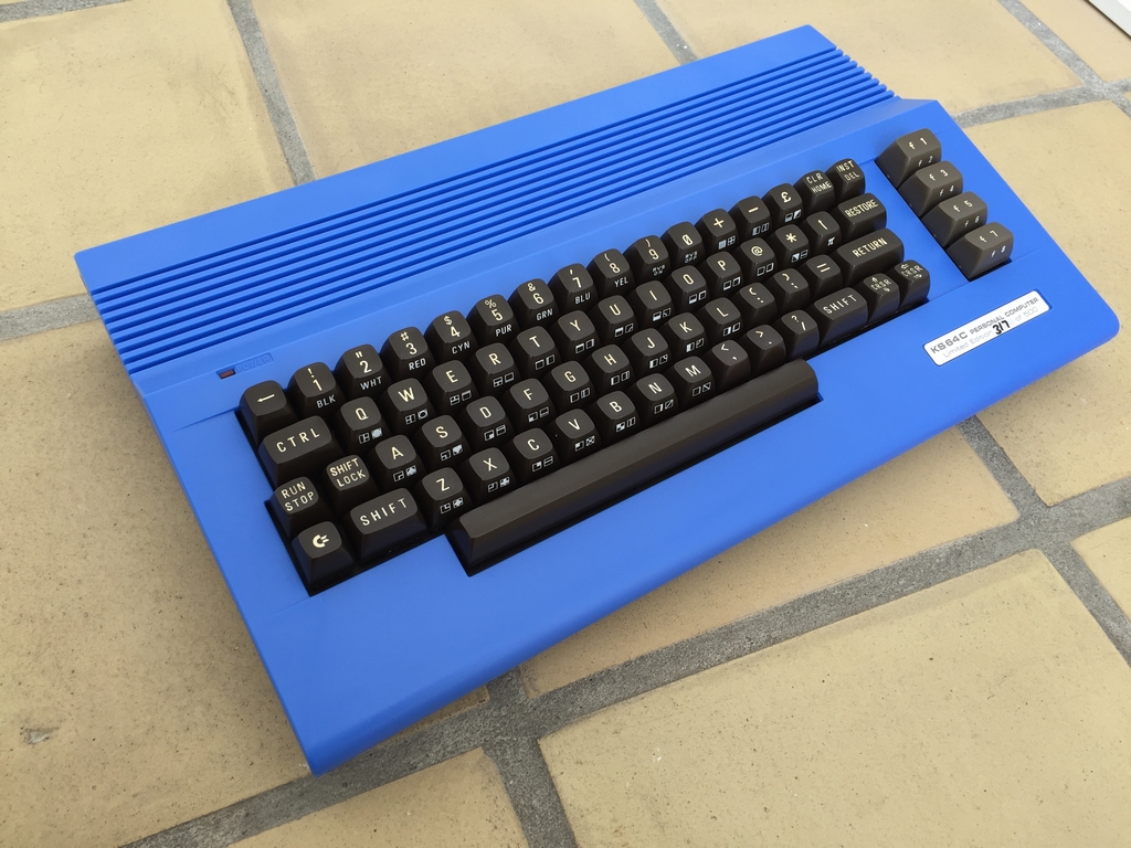
Well, there is not much to report as the MechBoard64 simply does what it is supposed to do – give inputs to the Commodore 64 regardless of motherboard version. The Shift Lock circuit works like a charm and turns on and off as it is supposed to. The MechBoard64 fits perfectly in both C64C slim cases and the old breadbox cases.
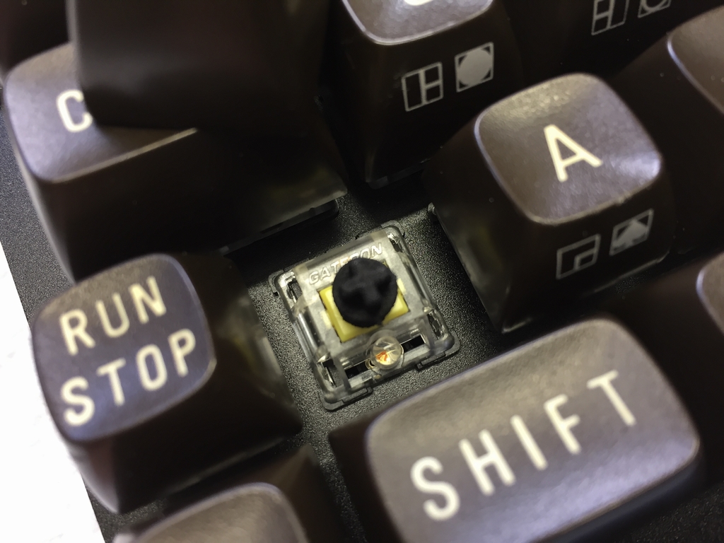
If looking closely at the images below of the keyboard inside a C64C case, it’s possible to see the wider Gateron microswitches underneath the keycaps. This is of course not possible on the old keyboard as it has, well no microswitches. All that is visible is the springs…
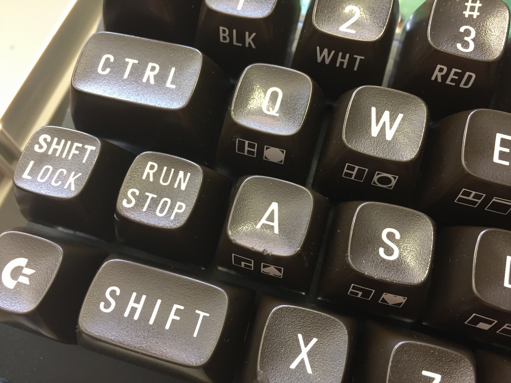
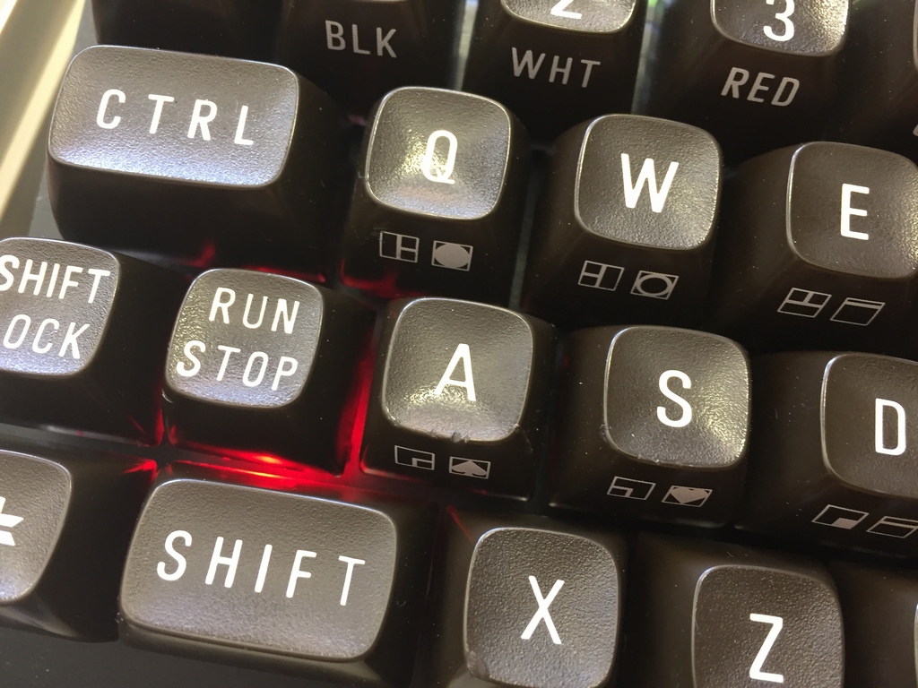
…and after waiting for more than two years, my C64 Reloaded machines have finally gotten their new keyboards… Now I just need need some keycaps. Please hurry up Phase5!
Final Thoughts
My little keyboard project has finally come to an end! I’ve spend 350+ hours on the project and the total cost of making the two keyboards exceeds reason by a very large margin… But it has been sooo much fun creating something usefull for my machines that I couldn’t just order somewhere. Hopefully they will last for at least 30 years! The final looks of the keyboard also exceeded my expectations by far and I’m really glad I abandoned the acrylic plate bracket and went for an aluminum version instead. The final version is very stiff and should be able to take some serious pounding…
UPDATE: Want to make your own MechBoard64? More information and instructions can be found here (link).
© breadbox64.com 2018
How would 3D-printed keycaps be in quality in comparison to other types of manufacture?
3D printed ketycaps would definately work. However, the finish will be different compared to plastic molded keycaps 🙂
so.. basically… that’s the final stage in reproducing new c64’s.
take a new c64c case from icomp, take the ultimate64-II mainboard (as the one icomp offers still needs the old chips you can’t buy anywhere), take that white psu boxy thing made by yet another company and take this keyboard… and you have a complete brand new c64. Btw scr** the ‘original’ keycaps. Why not just take any keycap that was designed for these switches and already is mass produced and just have the commodore pictures lasered onto them instead. Same mold, for all I care even the same grey plastic, just different images on the keys 😉 (or would normal keycaps be too low to come out of the case or something)
Now all that’s needed is a shop that sells it all in masses, in one place. Preferably already assembled and put into one box 😛 (the keyboard has been the ‘missing part’ for years now, all of those chips have had fgpa replacements for ages. The case molds popped up again, nobody even wants the original PSU as it’s a death trap so there are at least 3 better mass produced replacements for those on the market. But nobody ever came up with a keyboard to complete the thing.
If the ultimate goal here is ultimately completely new machines with completely new parts, then the need for keycap adapters and old keycaps may not be ideal for achieving it. Doubleshot PBT keycaps are really expensive, but UV printed keys are pretty attainable in small, even single-unit quantities. The question is … will standard keycaps even fit the C64 housings?
I would love to be able to use a Commodore 64, built brand new from new parts like this as a daily driver for work. Maybe if someone can develop GEOS 3.0 and develop enhancements to the GUI for daily use…
We can deal with the graphics not being the best, but memory, disk speed and networking would be a problem – so you should consider increasing the RAM (as if you had a expansion module built in) – include a SD Card reader in the side somewhere, so we can use SD Cards like small floppies and give me an Ethernet port or wireless so I can actually send an email.
I believe all of these things have already been developed – either here or by others working on different projects.
You should start a manufacturing collective, gathering parts from all the other projects out there and assembling them here into a kick ass C64R (R for Reloaded)… Use the newer C64c style case, it looks better than the breadbin – dare I say it.
Have you considered releasing a variant of the MechBoard64 which works as a USB keyboard? It would be a good complement to both software emulation running on modern PCs and … certain hardware C64 replicas which use USB keyboards. An integrated dual USB hub would be ideal, as that would allow joysticks, USB drives, SD2IECs, and also mice and normal PC-layout keyboards to be plugged in.
Hi Leo, I have actually played around with the idea of implementing a small circuit that would enable USB connectivity. To keep the MechBoard64 in its current form, I think the best approach would be in the form of e.g. a cheap daughterboard that can be inserted directly onto one of the 20 pin male connectors. It could also be one of the smaller (and cheaper) Arduinos with USB integrated. The latter doesn’t have the USB hub you talk about. However, having a readily programmable platform will certainly make things happen a lot faster in comparison to developing a new PCB 🙂
What an amazing build! Are the new C64 to MX adapter .stl files that you improved available to download at all?
Hi Patrick, I did not alter the orignal .stl that much. I basically filled the top right hole with a logo plate 🙂
Just wanted to say I’m really interested in this product as I am going to build a new C64 soon. Looks fantastic!
Is there gonna be a 128 version of this? I have a 128 that needs this due to a sticky “,” key 🙂
Now, we just need a version that will fit the SX-64!
God I wish I could buy one of these.
Instant buy if they are ever massproduced. These would sell out in seconds.
Wow, definatley interested in a pair of those.
Hi, build a SX-64 keyboard version, please !!!
This is awesome – have you considered partnering with someone to produce these for sale? Guaranteed people will buy.
One thing I don’t understand, is why doesn’t someone just re-release the C64 with modern / better parts? Not like that full-sized C64 mini – which is closer to the original but still not fully compatible, i.e. missing various ports and connectors. And not like the C64x which was missing all the original controller / cartridge / cassette ports and way overpriced. Just rerelease the C64 but with a super reliable power supply, quality keyboard (like yours!), all the original switches, and 100% compatible with EVERYTHING. The only difference would be maybe build in composite video out, put the chips in sockets (for easy replacing), maybe build in HDMI & VGA out (probably not needed but would be nice). Someone ought to do this with the C64, Atari 800, Atari VCS (the flashbacks are decent but should have a cartridge port) and Vectrex systems.
Thanks for our comment. I have released all the information needed to make your own MechBoard64. You can find alle the information here (link, link).
I would kill to be able to buy a Mech64 with Cherry MX blue switches for some clack to my classics. Can guarantee a buy from me if these are manufactured.
Hi Rob, I don’t make the keyboards, sorry 🙁 However, you can make one yourself if you are up for it. Files and building instructions can be found here: link, link. Sometimes you may be able to find a keyboard on Ebay. The last option it to keep an eye out for group buys. Escpecially the German forum forum64.de (link) have been running a few of these lately. Good luck with your MechBoard64 quest 🙂
Unreal. Every time I think I’ve seen everything for the c64, there is yet again something new. Awesome work! If I ever get back into the c64 (I have a lot of them from my dad buying them for us back in the 1980s), I’ll have more stuff to get than I ever remember.
@madscientistjr: Well, you should definitely check out then: ultimate64.com (link)! 😀 There you can get like almost ALL of that you mentioned in your posting: A reliable ‘new’ and fully compatible c64 rebuild with hdmi output and much, much, MUCH more for today’s retro-fans and phantasies !! 😀 I own lots of original hardware myself and also several of those ultimate boards and I can just say: IT ROCKS HARD !! 🙂 Best thing ever I have seen besides any original c64 machine!
Only thing (still) missing is a _new_ and cool keyboard-rebuild to date. This is really almost the ONLY thing still missing today, I’d say. 😉
But who knows… there seem to be certain projects for this, too, though… hopefully… 😀
Have lotsa fun (everyone), bye, Weasel…
My Dupont connectors are quite loose and don’t really hold onto the pin headers, did you use anything to make them more secure? Or do you think it might just be the crappy off brand connectors I got from Amazon?
I never experienced any issues with the ribbon cable connections. I assume that you are making your own cable which is why you’ve got the Dupont connectors, right? I got mine from this Ebay seller: link 🙂 They are a really tight fit!
You mention that your aluminum keyboard frame is bent by hand. Did you do this yourself? I only ask, because after modifying the AI file to work better in their web app, Oshcut.com is showing me that the flange perimeter on the first bend of the top inner-most bend won’t work due to too many cuts so near the bend in that top row of switch cut-outs. I’ve been considering changing those swtch cutouts to just engraved and using a Dremel to cut them out manually myself after the fact, but then their app informs me that the deburring and powder coat process will cover up the engraving, so I’m considering what my next move will be… Perhaps skip the deburring and powder coat process, do my own cuts for that top row, and then take it somewhere local to get powder-coated?
Hi Craig, Sounds cool with engraving the bracket 🙂
What I meant by ‘bending by hand’ was that each bracket was bend individually using some kind of metal bending machine. A person has taken the metal sheets (after the cut-outs for the switches were laser cut) and carefully lined them up in the bending machine and bent them one by one. Each bracket therefore had some bending tolerances within about 0.5-1 mm. Thus no, casting mould or similar device was used for the bendning process.
I do not know the exact reasons for the issue you describe with the to top row of the switch cut-outs. However, care should obviously be taken to ensuere that enough space i available for that row as it is really close to the bend. I used a factory in China for the manufacturing. You can find the information here: link
Good luck with the project!
Beware, not everyone who claims they can make these can.
I have purchased a set of 5 from Ebayer claining to know how to make them, that I was going to gift to my old school commodore club friends and all 5 have issues and now I’m stuck with 5 that need to find someone who can diagnose the poor job.
If anyone here can recommend someone who can take on 5 boards to diagnose, I would be very happy to work something out as I have to save my investment somehow.
Hi Ron, I can help you and diagnose those boards. Tell me what problem do you have ?
What is the size of MechBoard64 adapters pack (file – MechBoard64_adapters_v1_02) – 83.3 x 11.1 x 47.07 ?
According to Shapeways where I get them printed, the size is: 47.08 x 83.39 x 11.1 mm. So your dimensions seem pretty close to what I got 🙂
Hi Jacek!
All thr boards fail at lighting caps lock in either jumper position. All the stabilizers don’t work, they fall off and I even re purchased from someone claiming to know how to make but all were unique, not plumb and didn’t work. Ever see a grown man cry over a keyboard?
Also the guy had boards made with pinout facing frame so I have to source longer cables to use them in breadbin. A couple survived bending pins. If distance is too far for longer cable, I might have to have the pin header removed and replaced instead.
It’s all a mess but irony is the work looks clean. Nothing looks sloppy. Maybe the micro components weren’t installed correctly?
I’m will to pay of course, just looking for someone who can get me back to where I need to be with the keyboards.
Already gave my friends their custom commodore with painter cases, they were happy regardless but I still want to rescue these.
I know it’s expensive to ship 6 units back and forth plus repair but I can’t give up and this requires serious experience.
If you can help, I would be very grateful.
I have the same problem with keyboard cable length putting a mechboard into a plexi laser cut case. The keyboard sits far forward. Where did you source the extension cables?
Just willing to express my congratulations to this gorgeous build!
Hi Steve, Thank you for your kind words. Much appreciated 🙂
Hello, is the MechBoard64 (as a kit with keycaps) available? I wanto to build my own new C64C.
Best regards, Thomas
Hi Thomas, and thanks for your interest in the MechBoard64. Unfortunately, I don’t sell the keyboard. However, you can find sellers on Ebay who sell them (at silly prices…). You could also try retrospective.shop (link) in the US. They should have kits to build. Good luck with your project 🙂