
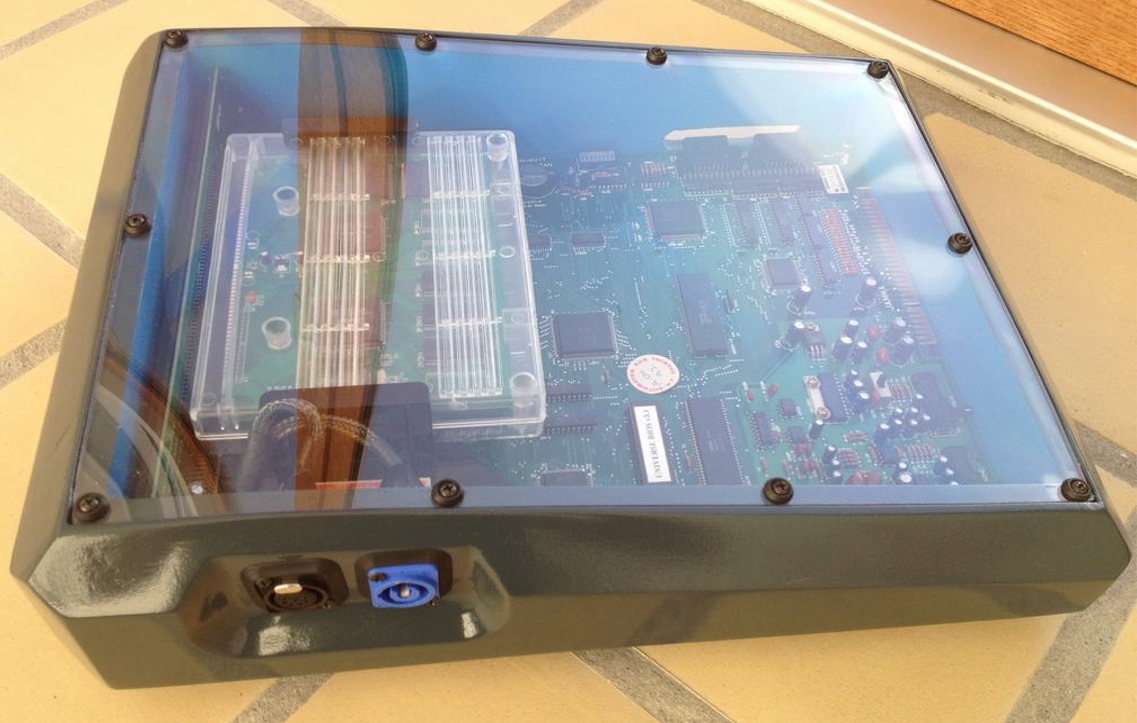
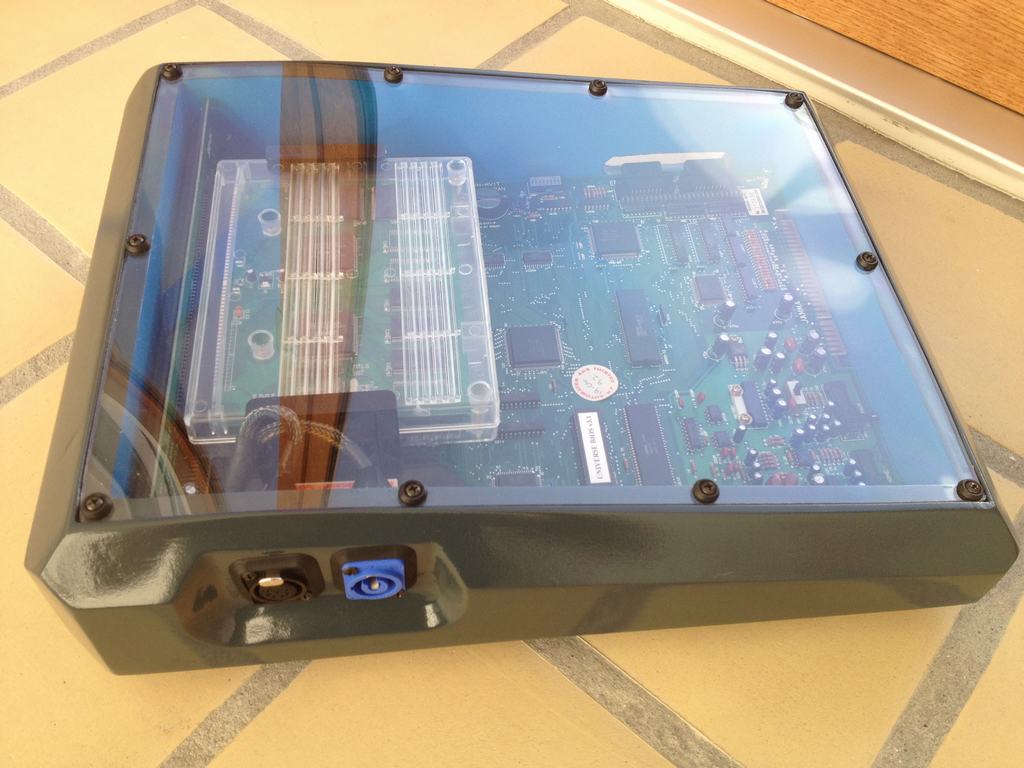
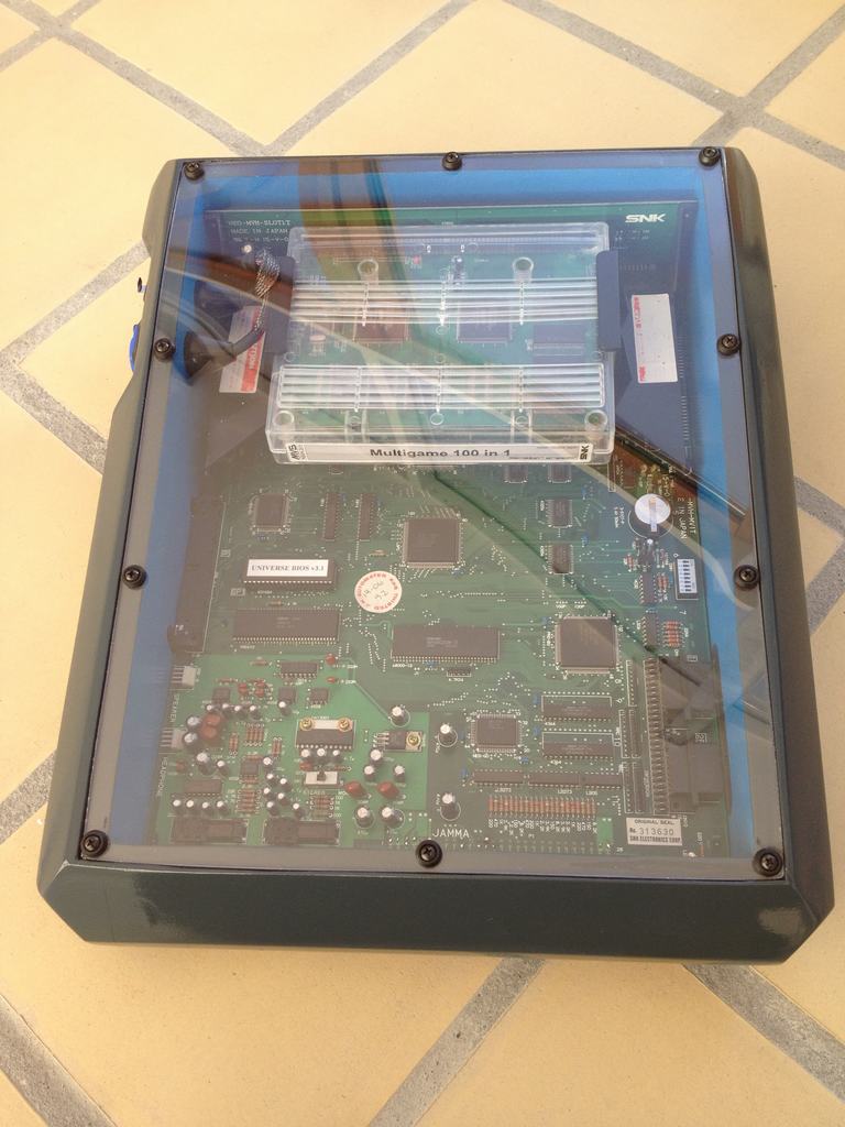
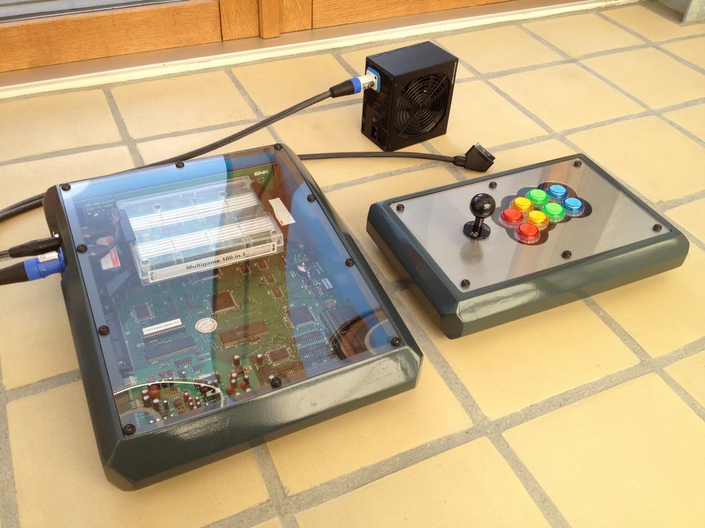
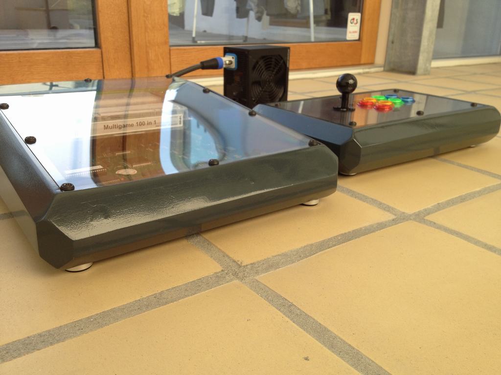
When I was done with the MVS Neo-Geo inspired Universal Fight Stick I moved on to modding a MVS Neo-Geo board that I recently bought. The MVH MV1T board is loaded horizontally which makes it quite a challenge to make a slot in a cased solution slot swapping carts. As I only had one cart which was a 100-in-1, I decided to just put everything under plexi glass. The case was build using MDF boards that were glued together and the edges were made using a table saw and painted in the same color as the Universal Fight Stick.
Power to the board and AV out using an Euro Scart plug were done using plugs from Neutrik.
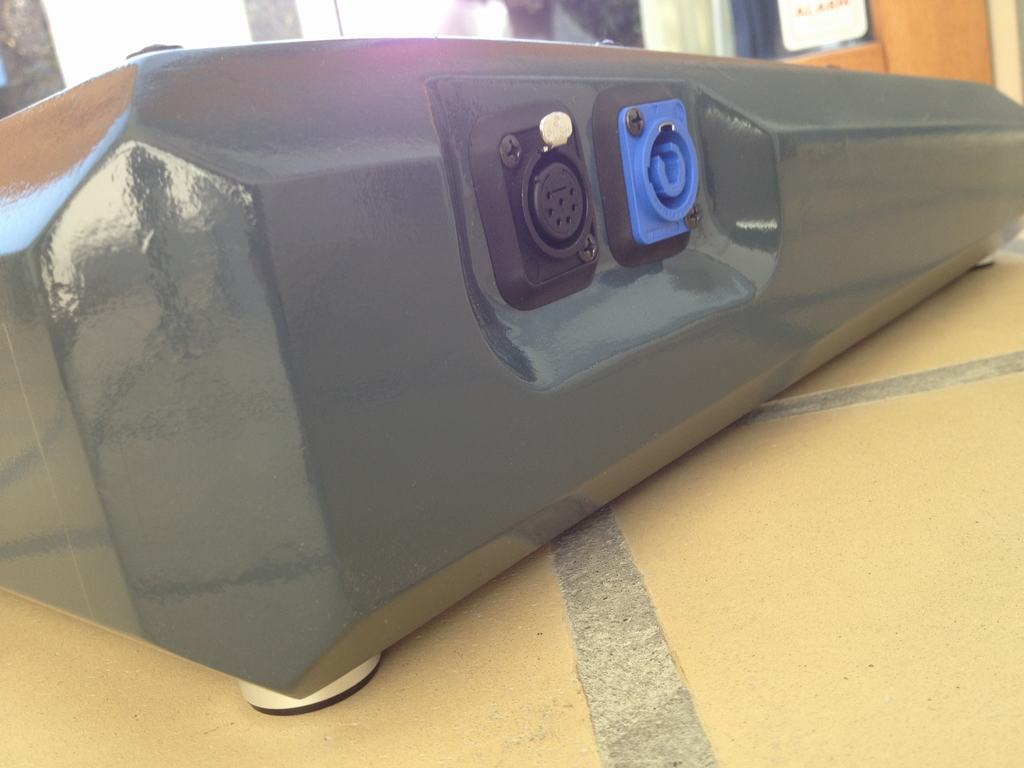
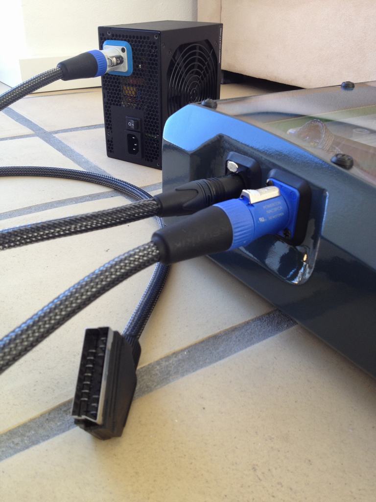
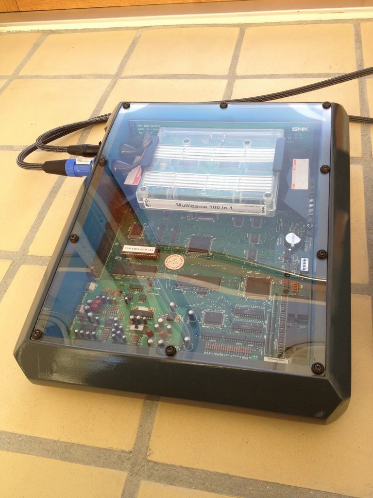
The cables for the AV-out were sleeved using carbon look cable sleeves.
Joysticks can be attached directly to the side of the board. I used a router to trim the sides of the hole.
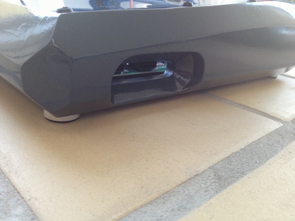
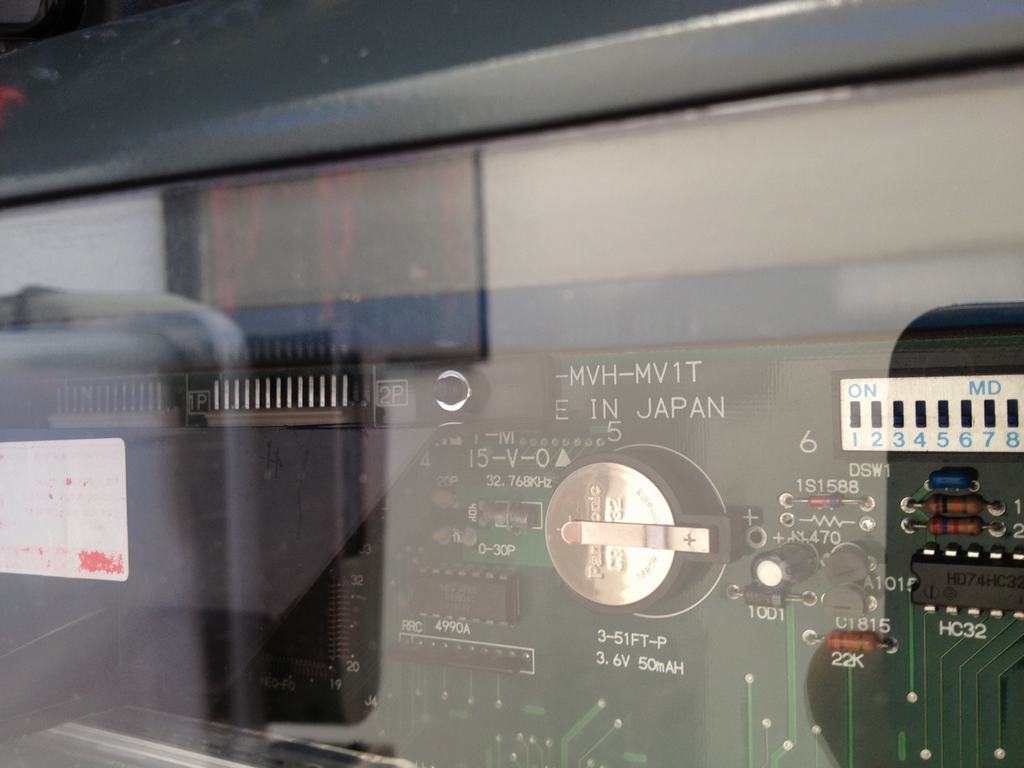
To keep the original NiMh battery from leaking and possibly destroying the board, a Lithium battery was inserted in its place.
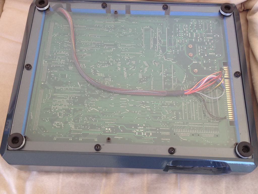
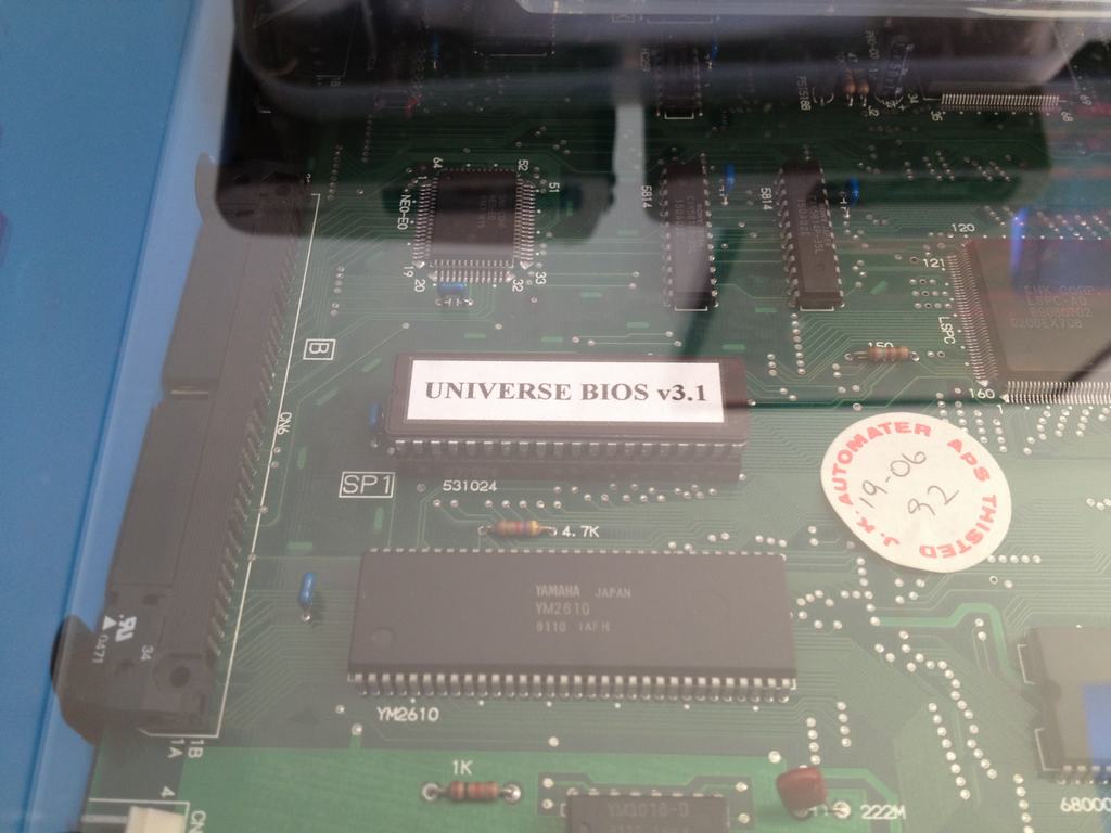
Finally, the board was modded using an Universe Bios for added functionality.
The complete gaming system with the Universal Fight Stick ready to be plugged in and played on…
© breadbox64.com 2015
Hi! Did you built the fight stick? I want to make a fight stick for my consolized MVS 2 slot. Do you use the joystick port on the board? Thanx
Yes, I built the fight stick myself 😉 You can find the build here (link). I use the joystick ports on the side of the board (link). That way I didn’t have to mount two extra joystick plugs in the wooden cabinet, including the hassle of all the wires 🙂
Good luck with the project!
As I’m preparing to consolize my 2 slot, I’ve been wondering why everyone is hacking and slashing their boards, rather than pulling everything they need directly from that big jamma connection staring them right in the face, like you did apparently. Its not like there aren’t plentiful diagrams available for these pins. Well done, looks awesome.
Yep, I couldn’t agree more! Why make it so difficult when all connections are right there – the boards even have the soldering holes to accommodate the wires.
Thanks for the positive comment and good luck with your project 🙂
I got one of these boards and was interested in consolizing. I imagine the wiring for RGB is the same as the others but what are the power requirements. I’ve heard both 5v and 12v but wasn’t sure which was correct for this model.
I used both the 12V and +5V line in the mod as these were readily available from the ATX PSU. The 12V line is primarily used to run a set of speakers when using the PCB in an arcade cabinet (which kinda spoils the whole idea of consolizing it…). It isn’t needed to have the board produce sound but the board uses the 12V to also power the opamps which run off +5V converted from the 12V line. Thus, if you want to omit the 12V line (and only use a single +5V source) you have to make another modification to the board as described below. I just found it easier to feed it both voltages as I used a standard ATX PSU 🙂
The +5V mod is basically done by joining the primary 5V rail with the secondary 5V rail. The primary 5V rail is the normal 5V rail that connects to the JAMMA edge. The secondary 5V rail comes from the 12V rail and gets converted to 5V using a 7805. The easiest way to do the 5V mod on most boards is via the YM2610 as it uses 5V from both rails. I have not done this myself, but I’m sure you can find instructions out there 🙂
Best of luck with the project!
Really cool project. Your attention to detail and the finish to all your projects is fantastic.
Thanks Neal. Glad you liked it. I really enjoyed making it 🙂