
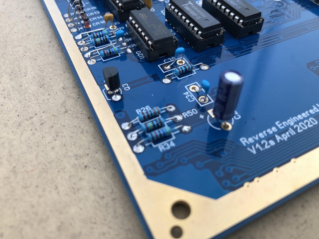
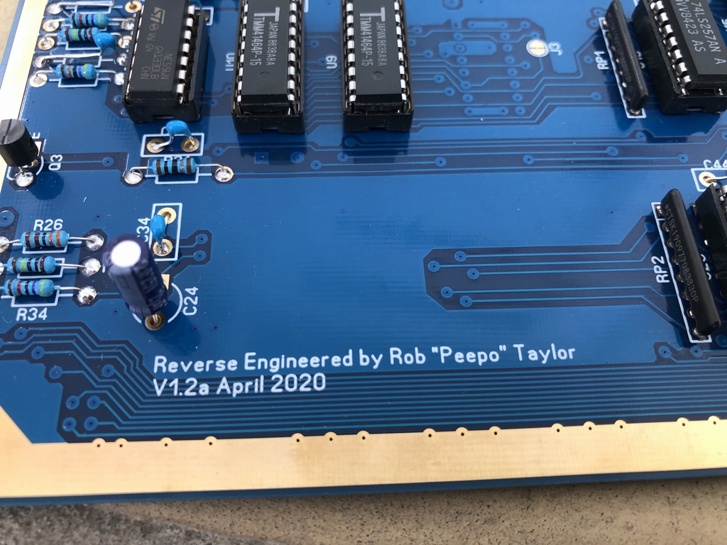
I recently treated myself with one of these nice blue Commodore 64 replica PCBs from Bob’s Bits on Tindie.com (link). After populating it with new parts (except for the orignal chips of course), I thought I would share my exprience. The SixtyClone is basically a reverse engineered replica of the orignal Commodore 64 motherboard PCB. The board is created to allow Commodore 64 computers that had damaged or faulty PCBs to be successfully repaired. This can be done by moving all components from an original motherboard to the replica board (or add in new parts as I have done). The PCB is created by Rob ‘Peepo’ Taylor who has made replicas of several Commodore 64 motherboards including two long boards (Assy 250407 and 250466) and one short board (Assy 250469).
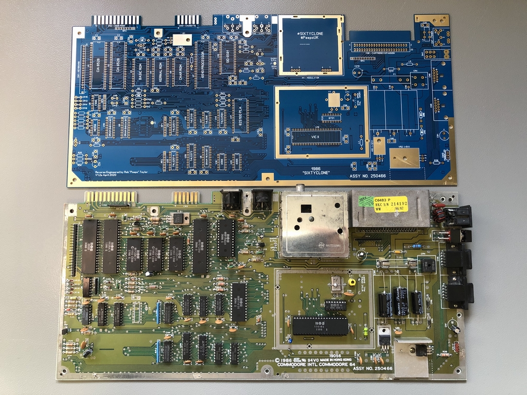
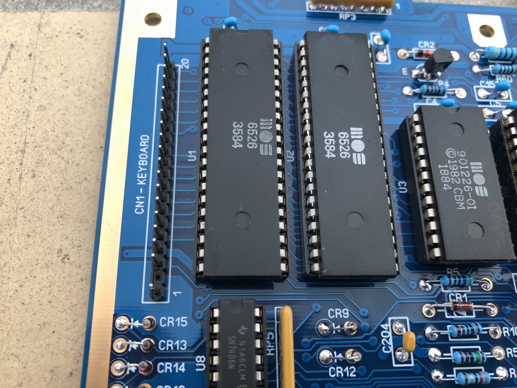
I opted for a replica of the Assy 250466 (Version B-3) long board in blue originally made in 1986. This motherboard is the predecessor of the later Version E short boards (Assy 250469). The biggest difference from the older long boards is the use of two 32 kByte RAM chips (41464) instead of eight 8 kByte RAM IC’s. Furthermore, it has fewer chips to install compared to the long boards and I did not want to mess around with the very large PLA (251715-01) memory control chip at U8 found on the Assy 250469 boards.
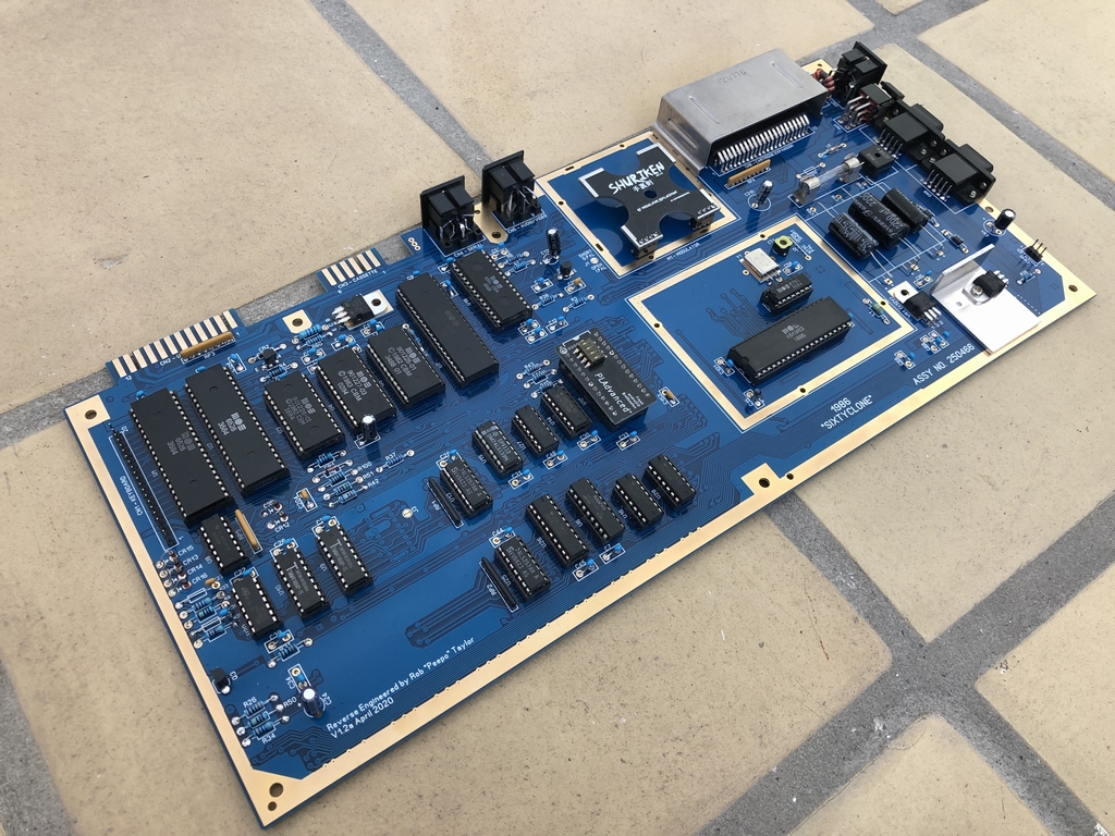
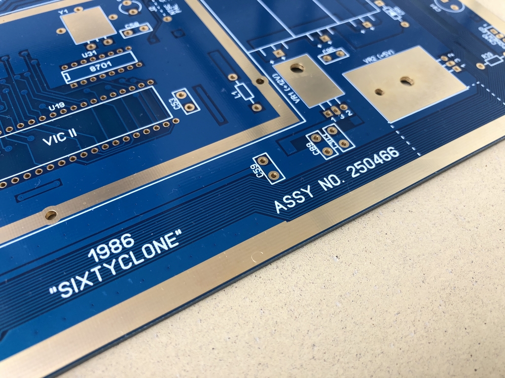
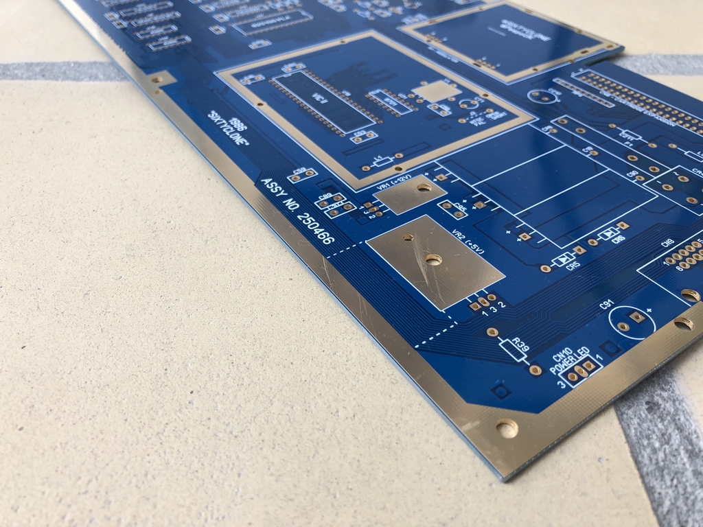
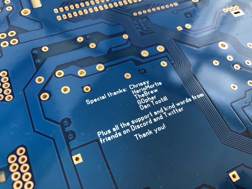
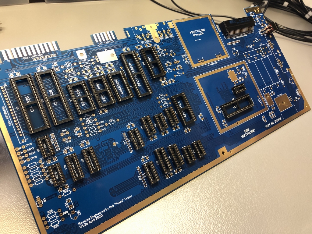
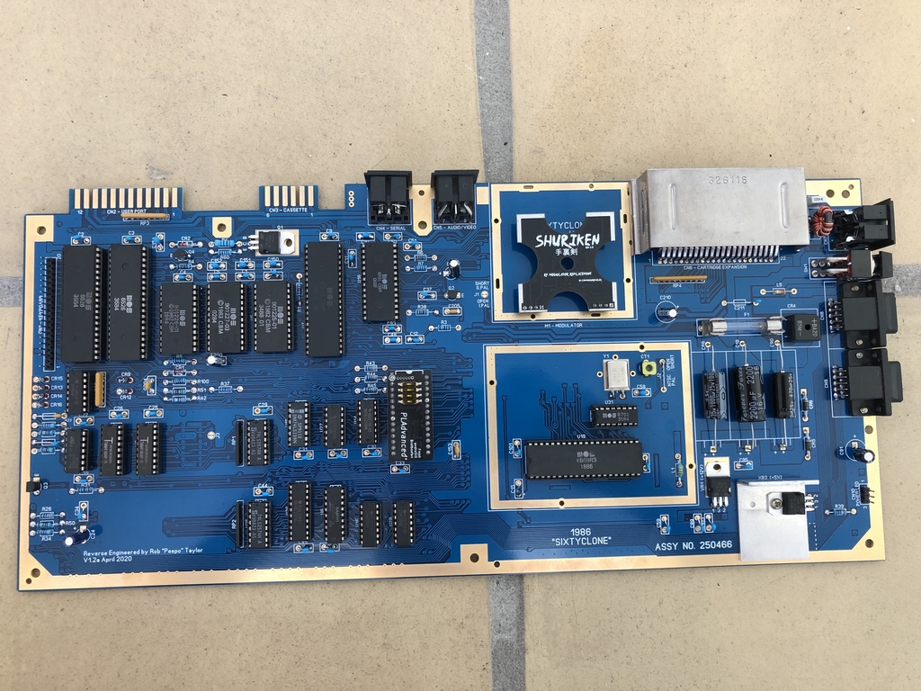
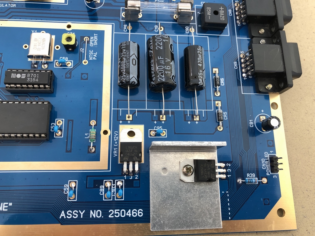
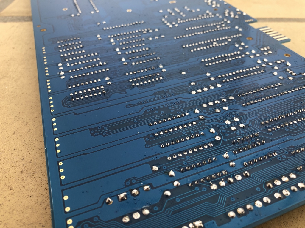
The SixtyClone Commodore 64 replica PCBs can be purchased in several colors and costs 35 $ + shipping from the United Kingdom. This is how my finished SixtyClone motherboard ended up looking – pretty sweet, eh?

The SixtyClone Commodore 64 Replica PCB
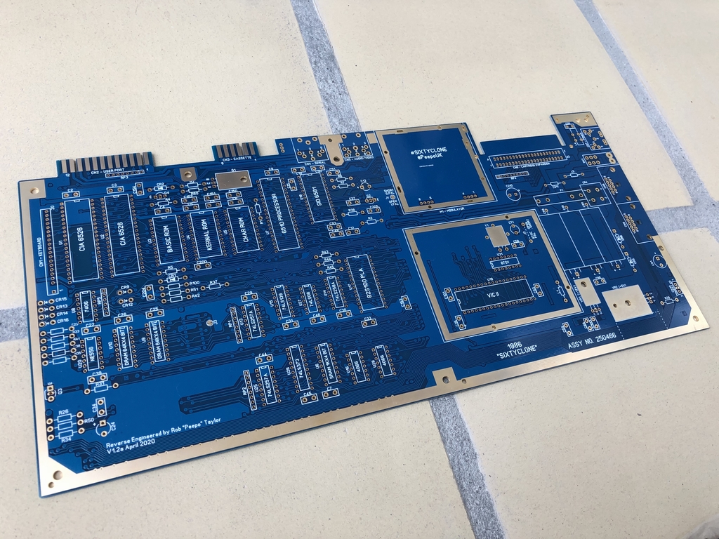
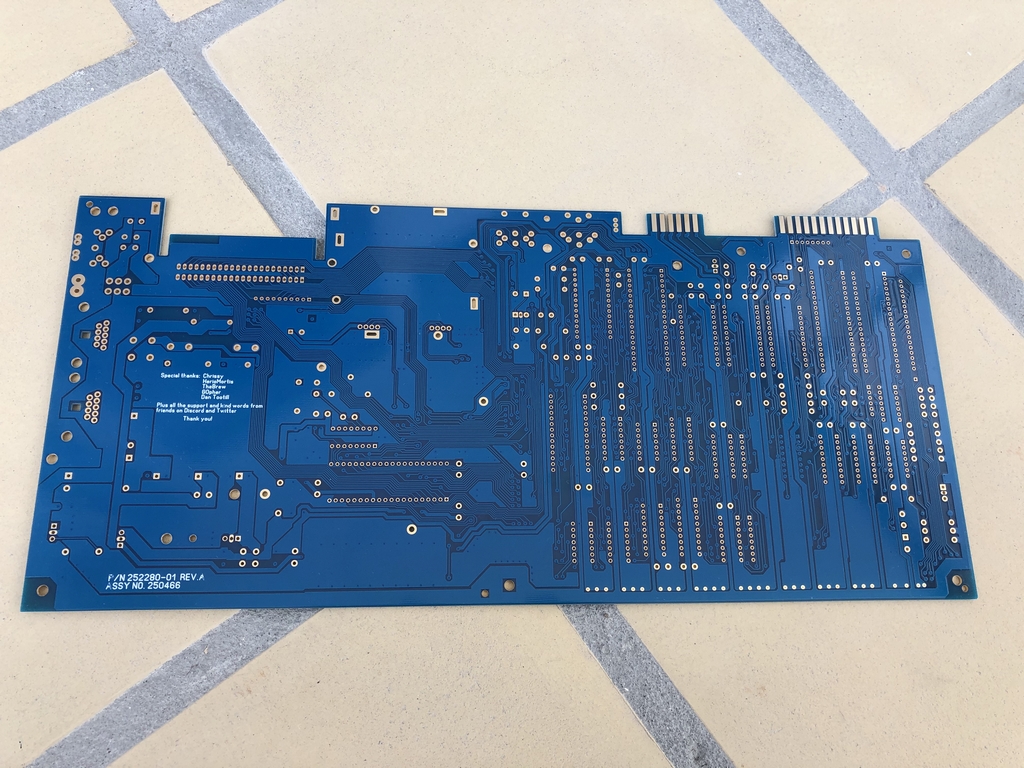
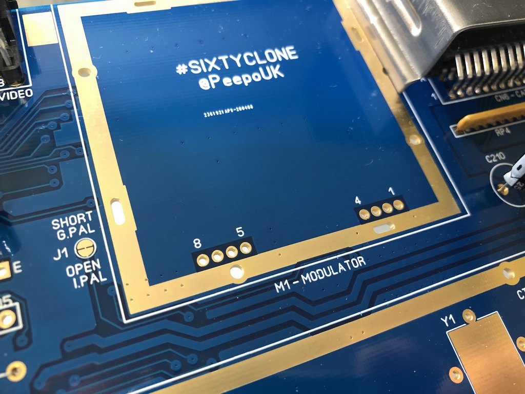
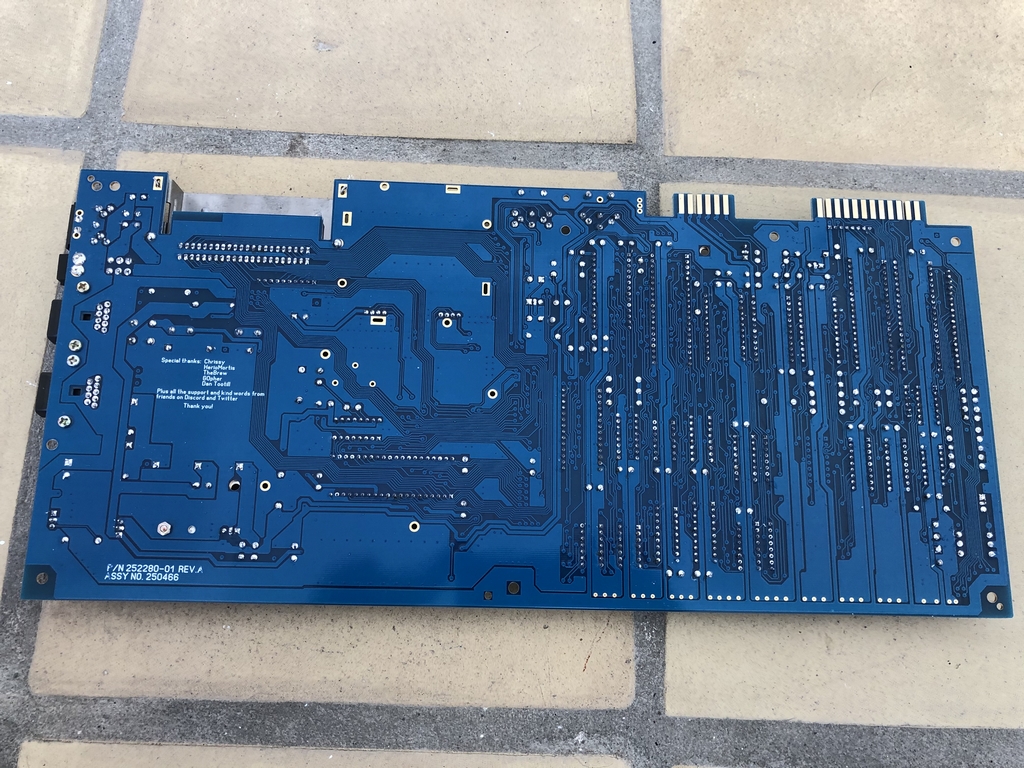
The modern-day Commodore 64 PCB has a nice blue soldermask and a white silkscreen. All open surfaces has been gold plated for an extremely nice finish. In general, everything looks very nice and of a really good quality! To make the build as easy as possible, I used my original Assy 250466 long board for comparison during the build (link). The naked SixtyClone C64 replica PCB looked like this when I received it from Bob’s Bits on Tindie.com.
Scavenging Parts
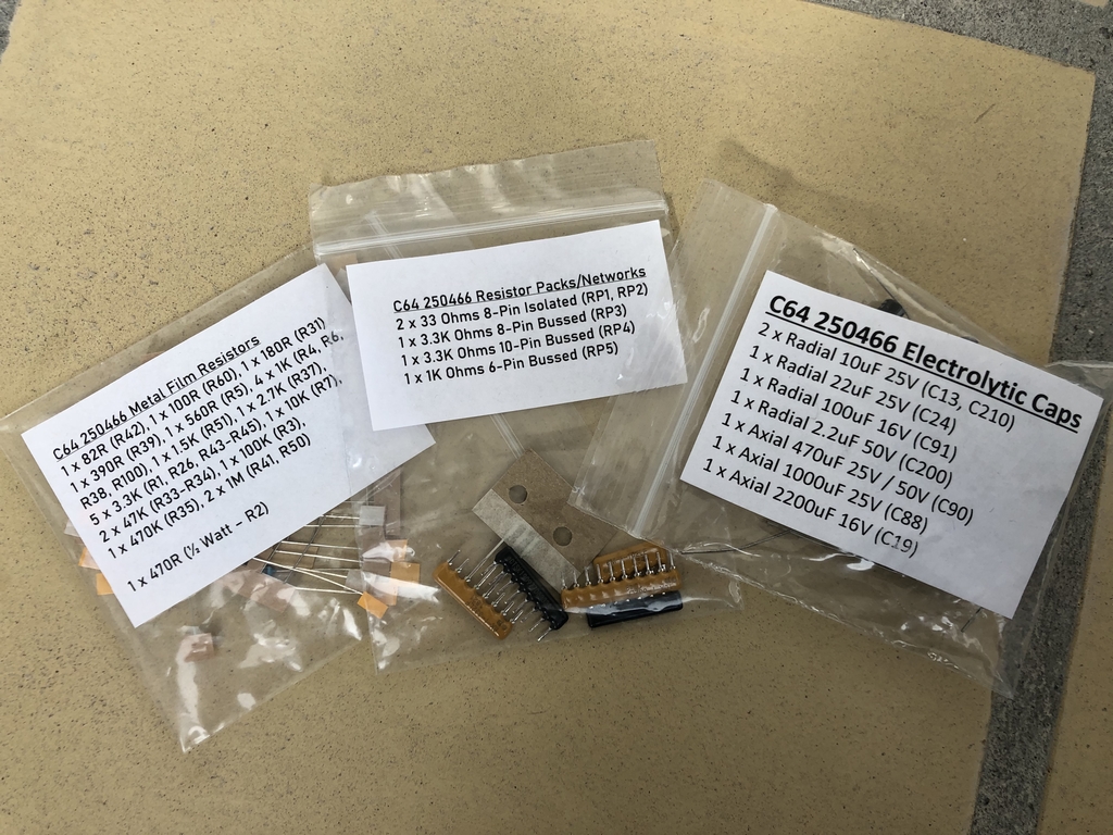
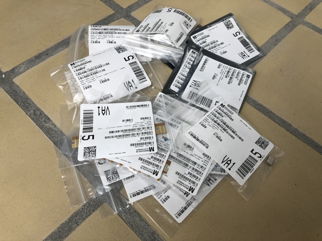
At reasonable prices, Bob’s Bits also offers a variety of optional extras to make the build as smooth as possible. This include resistor packs, electrolytic capacitors, resistor networks, SwinSID nano b, replacement power switch and a GAL-PLA. I opted for the capacitor pack, the resistor pack and the resistor networks. I already had a heap of new parts including sockets, a power switch and a cartridge port. The rest of the parts were ordered from Mouser or taken from a spare long board (Assy 250425) that I use for parts. A Bill of Materials (BOM file) with part numbers from Mouser can be found on the Tindie ordering page (link) and made it quite easy to order all the parts needed for the build.

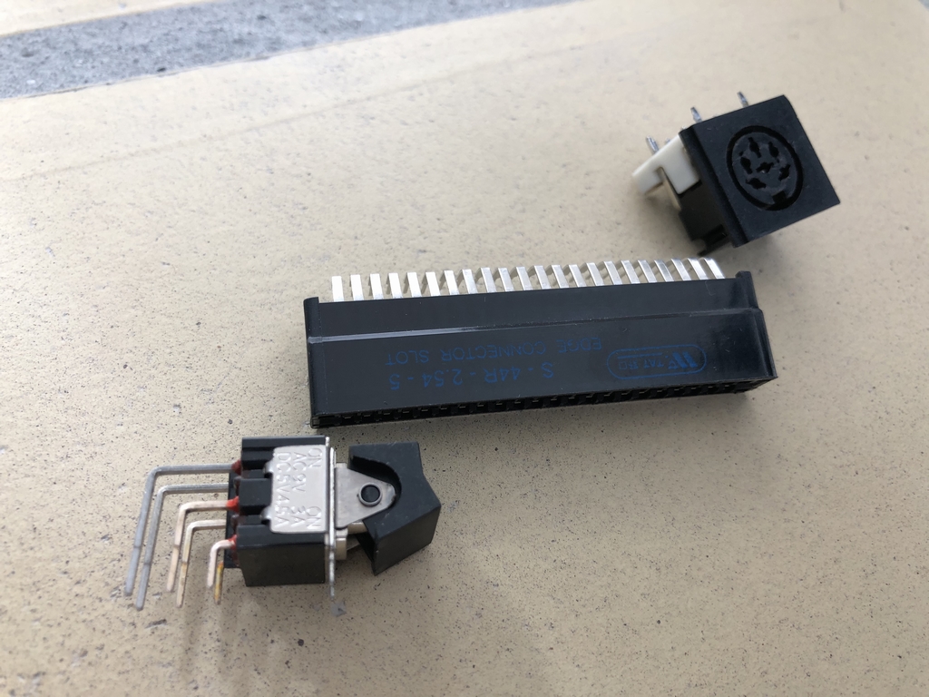
Heating up the Soldering Iron
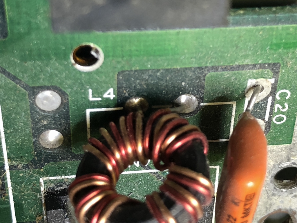
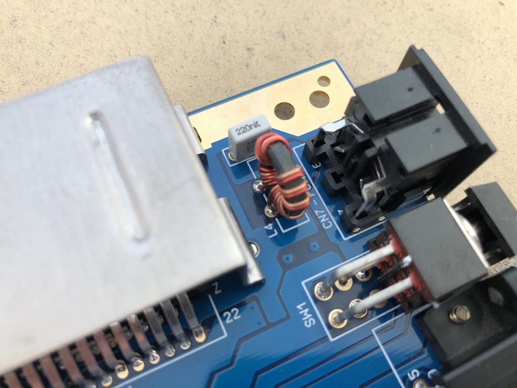
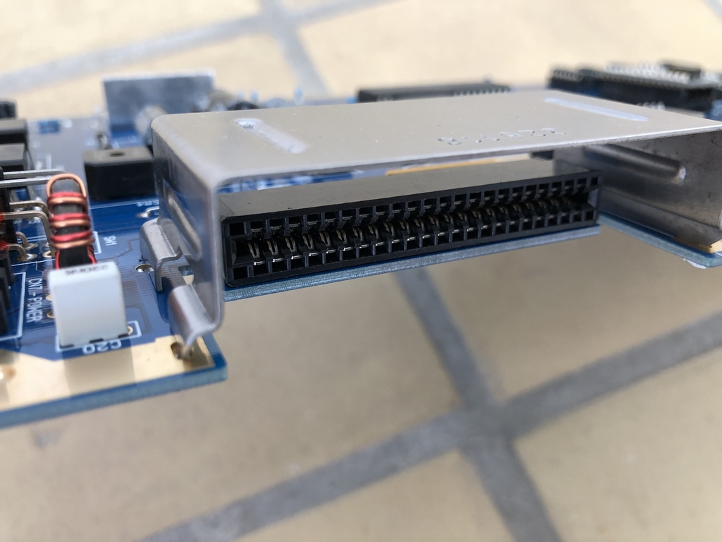
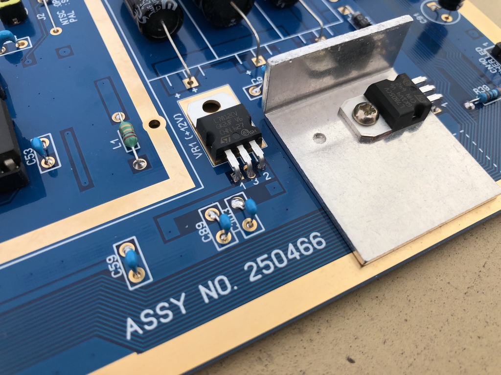
First up was soldering in all the sockets. This was quite easy – and fun! Next up was soldering in some new 5VDC (7805) and 12VDC (7812) voltage regulators that I got from Retroleum Spares Shop (link). The metal cooling plate for the 7805 chip was taken from the old long board that I use for parts. The 5V line filter at L4 is not an easy part to find online, I therefore desoldered an original one from my spare motherboard. The metal bracket at the cartridge port was also taken from the old long board. I removed all the stickers and polished it slightly to make it look brand new. I think the result is pretty nice!
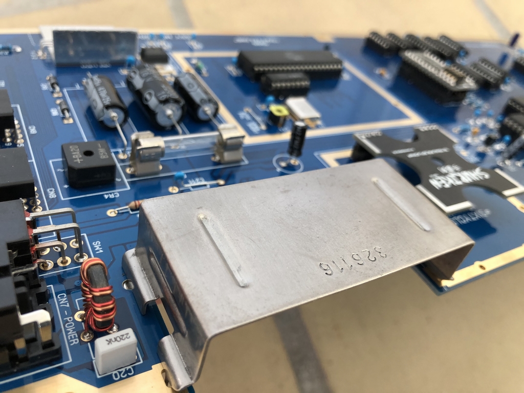
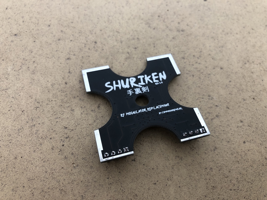
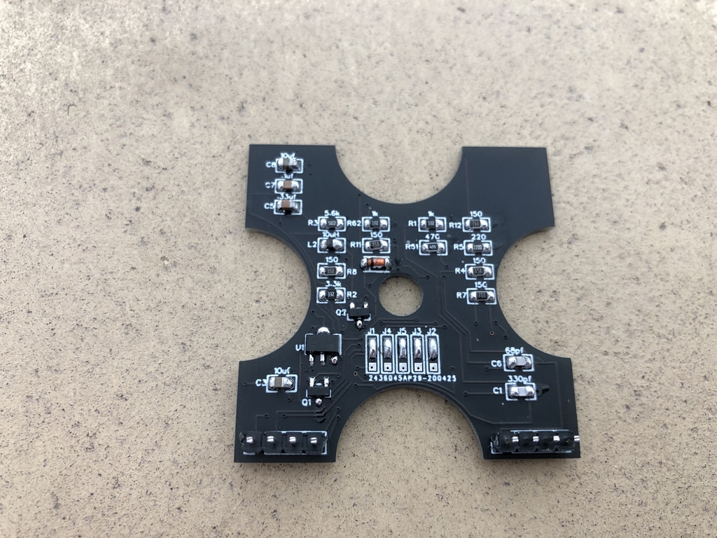
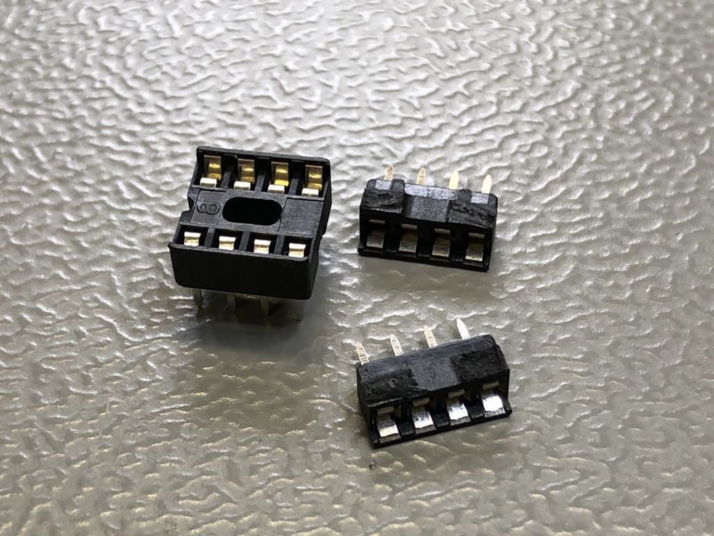
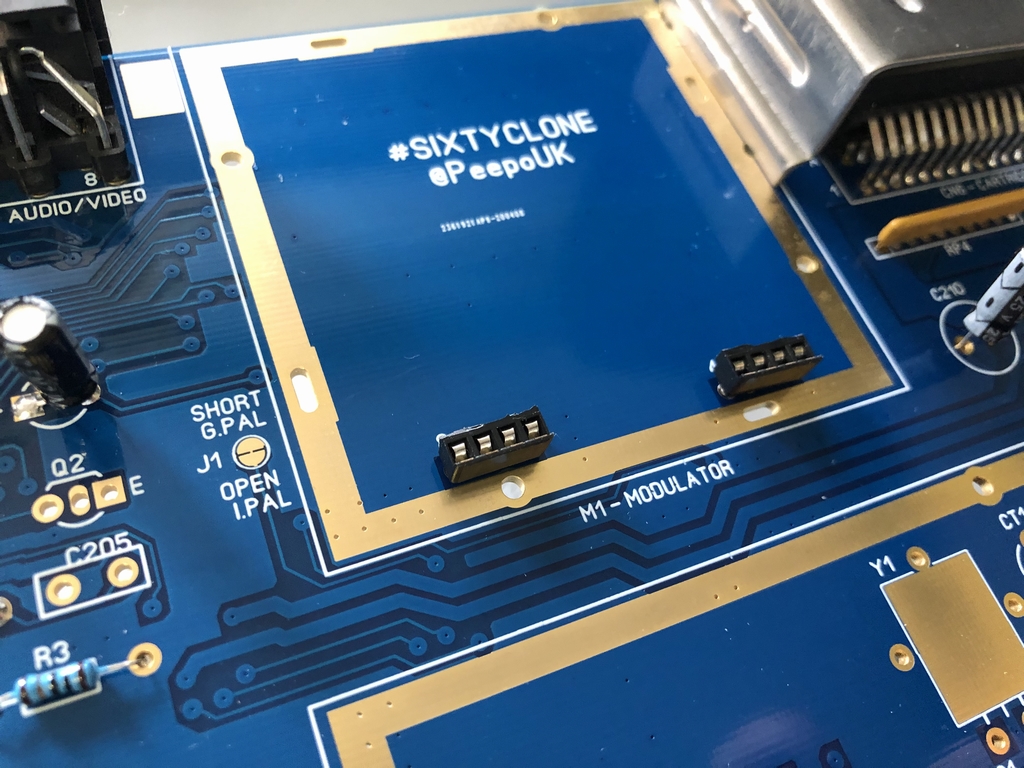
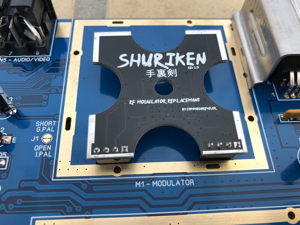
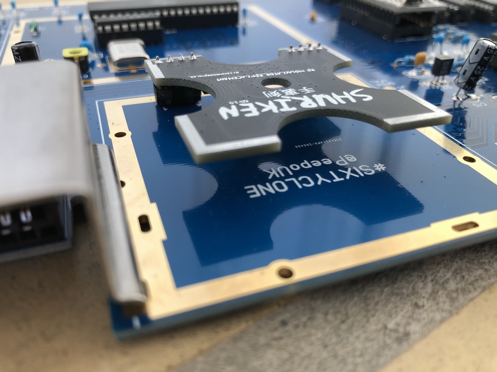
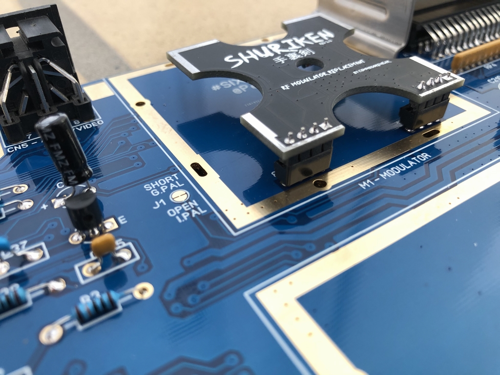
Next up was the RF modulator. I did not want to put in one of them old ugly metal RF boxes from an origial Commodore 64. As the RF box holds the circuitry necessary for S-video output (luminance and chrominance), it cannot be left out without some kind of replacement circuit. I therefore installed a black Shuriken RF modulator replacement board from commodore4ever (link). It is really small and completely removes the aerial connection. As I always use the S-video output, this was not a real sacrifice for me. (A more comprehensive review of the Shuriken RF modulator is on my workbench at the moment so staty tuned!) I soldered in some small sockets to make the installation as easy as possible.
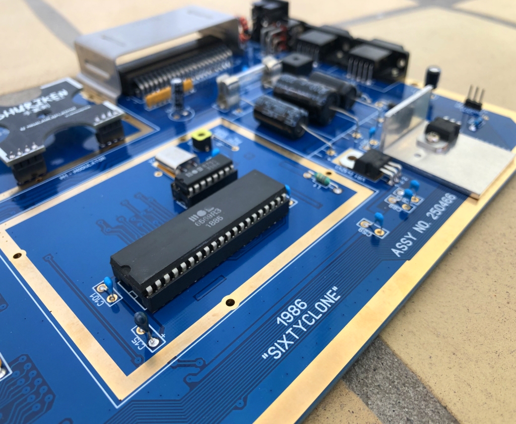
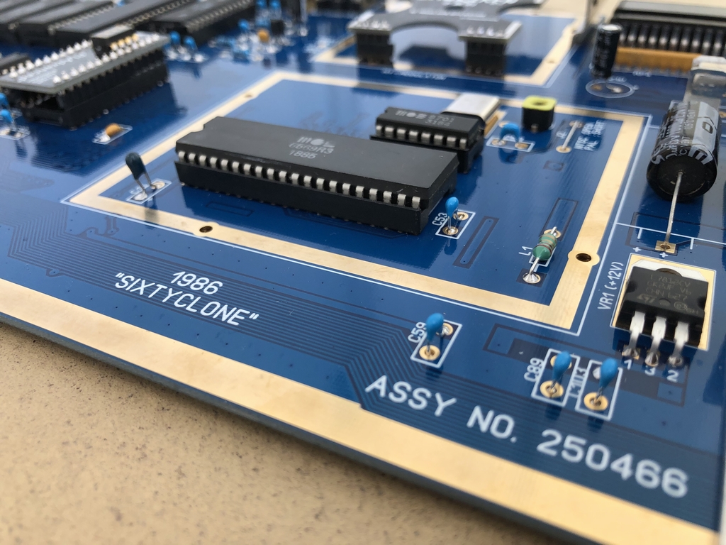
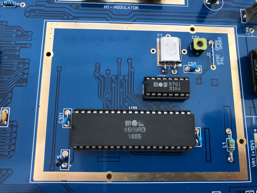
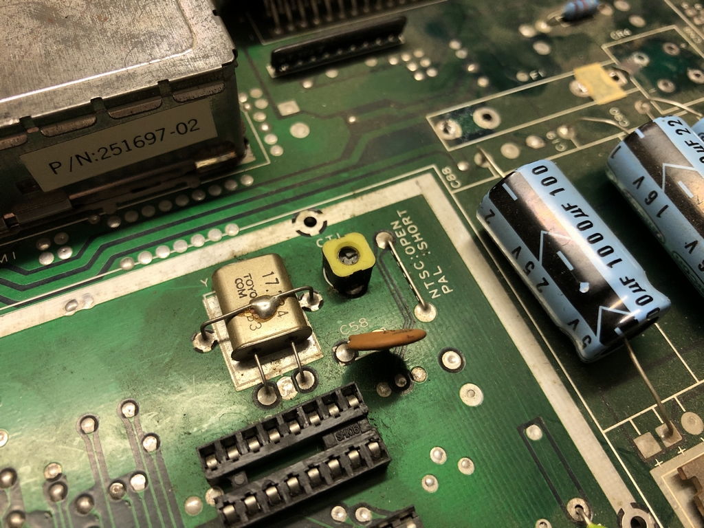
It was then time to populate video area of the board. The VIC-II video chip (MOS 6569) and the 8701 chip were inserted into the sockets. The frequency crystal, the inductor coil at L1 and the ceramic capacitors at C58, C53 and C101 were all new parts and were quickly soldered on to the PCB. The 6.5-40pF trim capacitor at CT-1 is not easily found as a new part – at least I did not manage to find it… I therefore desoldered it from the old long board along along with the radial tantalum 4.7uF 16V 20% capacitor that I did not find as a new part either.
Finishing up the Build
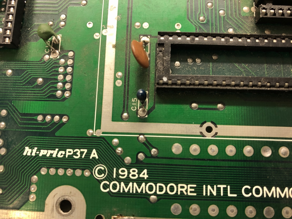
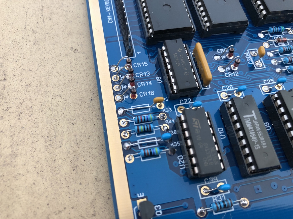
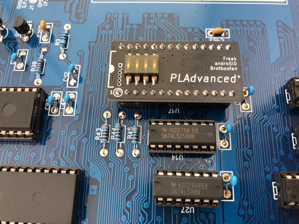
Now it was time to install heaps of electrolytic capacitors, ceramic capacitors, resistors, resistor packs, diodes, transistors etc. The orignal Commodore 64 Assy 250466 has an axial 51pF ceramic capacitor installed at C38. It is usually build into a green resistor case. The capacitor is also known as the ‘NMI Capacitor’ and it is misdimensioned which causes the RESTORE key to be hit hard to function. On the new short boards (Assy 250469) the problem was fixed. The solution to the problem is to exchange it with a 4.7 nF capacitor as I have done previously (The C64 RESTORE mod can be found here: link). However, as I did not have a spare 4.7nF capacitor I simply used a 1.8nF instead as I had pleanty of these in my spares box (they are scattered all over the SixtyClone motherboard!!).
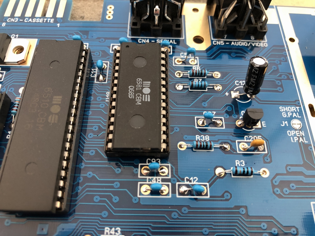
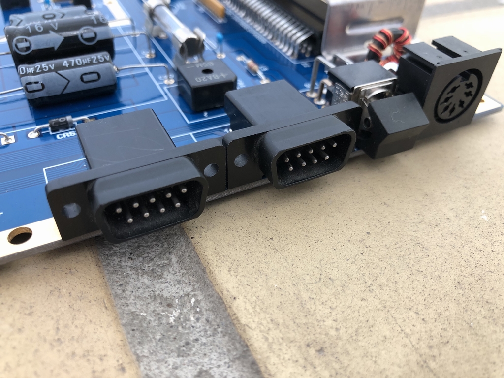
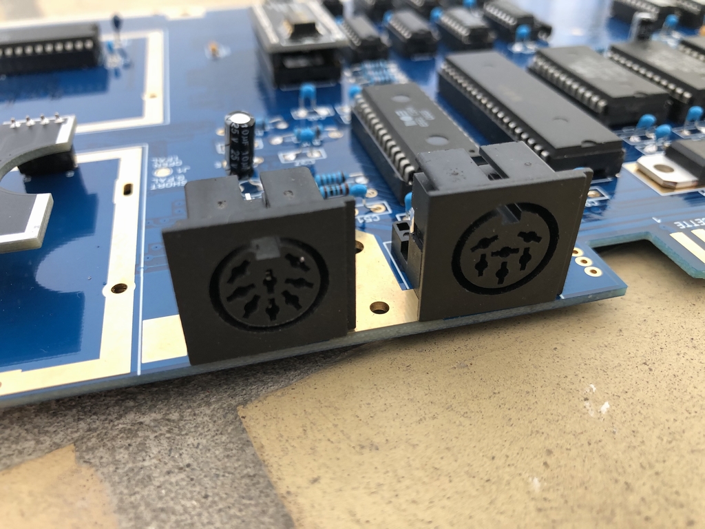
To finish up the build I installed a PLAdvanced+ (link) at U17, a new power socket, two salvaged joystick ports, a new audio/video socket and a new serial/IEC connector.
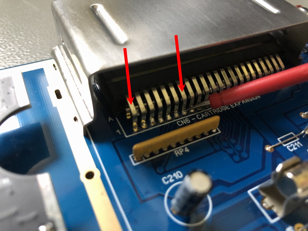
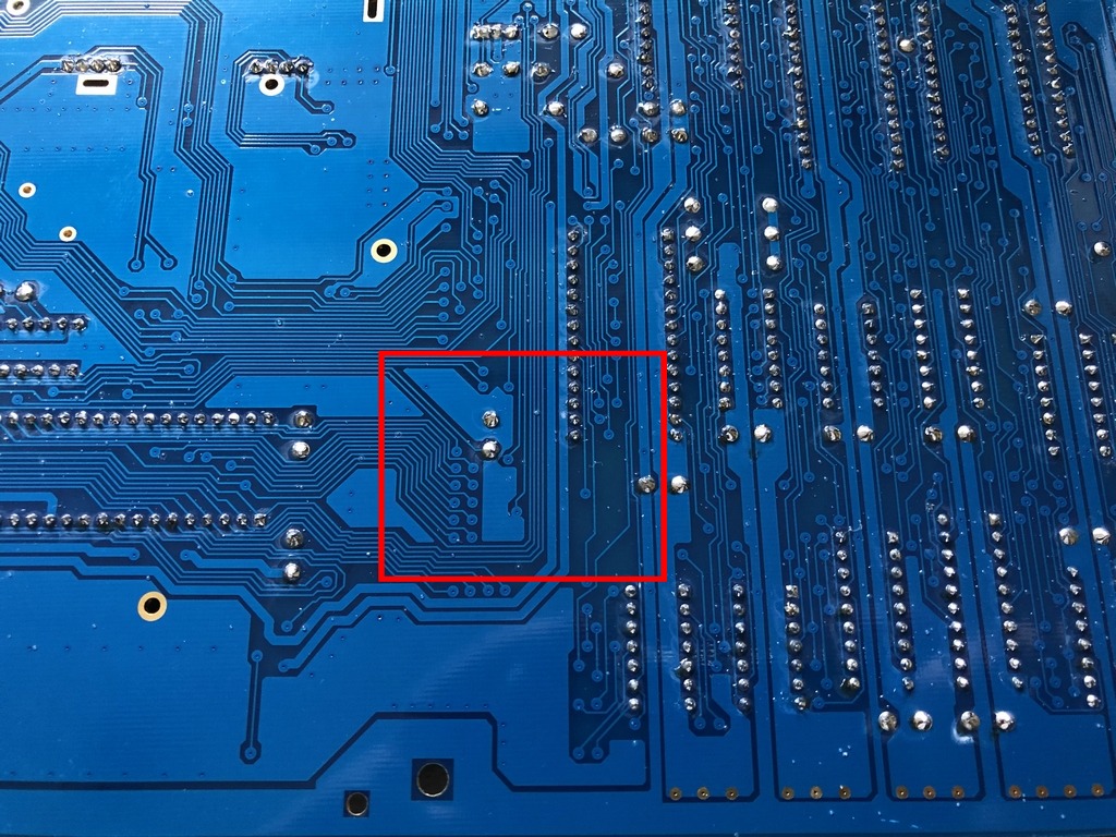
Pin 7 Issue
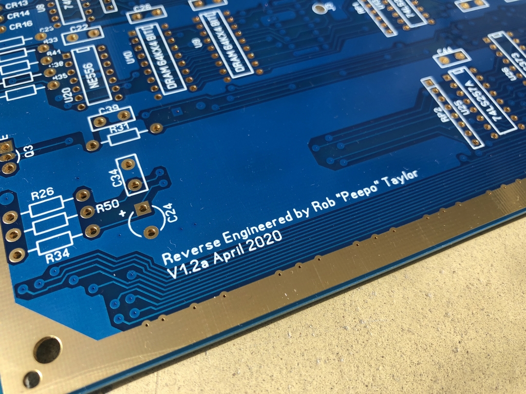
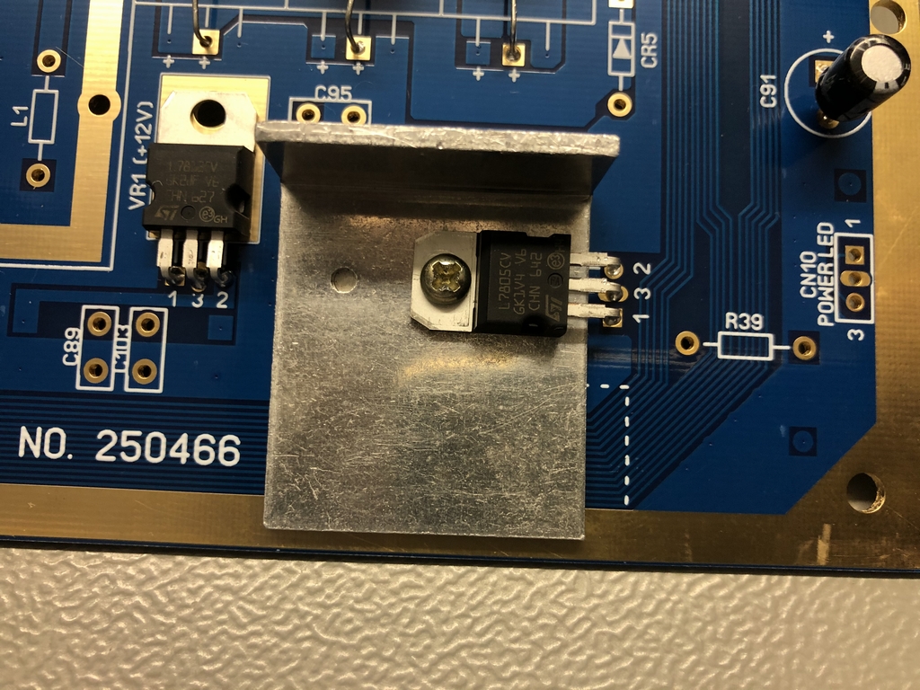
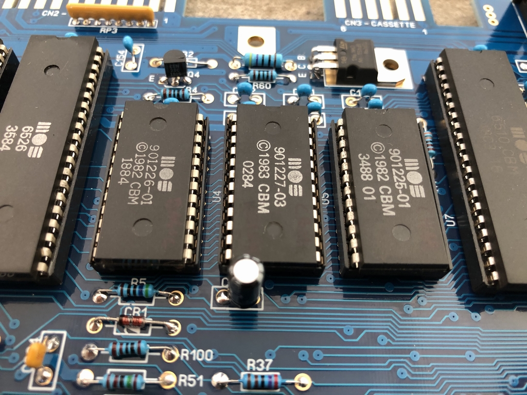
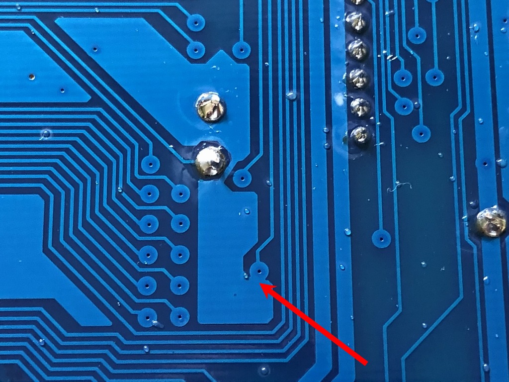
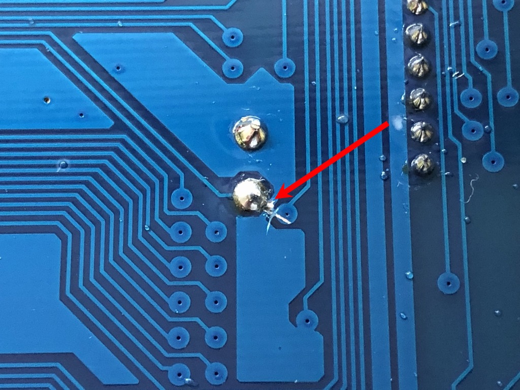
Unfortunately, some of the SixtyClone boards produced before version 1.4 have an issue where pin 7 of the cartridge port is connected to ground (GND) by a slightly misplaced via. My board is a version 1.2a and a quick test revealed that my board was affected. This was done by testing for continuity between pin 7 and ground (pin 1) of the cartridge port. As seen in the images below, the via touch the ground area of the PCB. The issue was easily fixed by cutting the connection as indicated by the red arrow in image 4. After cutting the connection, I double checked that the fault was fixed by testing for continuity between pin 10 of the 74LS139 chip at U15 and pin 7 of the cartridge port. The connection between pin 1 and pin 7 of the cartridge port should obviously not be present after the fix 🙂
As a side note, I actually tested the fully populated SixtyClone board unknowingly that it had a ‘Pin 7 Issue’. A that time I did not find any faults, altered functionality of the machine nor did any components burn on the PCB. But it should abviously be fixed if populating one of the affected board.

Self-Success?
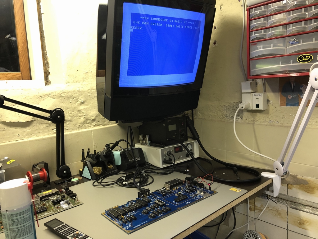
It was finally time to see if everything worked as expected. Wouldn’t it be great to be greeted by the sweet blue Commodore 64 BASIC screen the very first time the power was turned on? After flicking on the power switch, the machine simply turned on like a charm!!! A quick run with my diagnostic 64 Doctor Cartridge gave me no errors as all. Everything had been put together without any mistakes 🙂 Nothing beats self-succes, right?
Final Thoughts
Well, there really isn’t much to report. The PCB from Bob’s Bits on Tindie.com works flawlessly. The price is very reasonable and the blue soldermask looks great with the white silkscreen. The gold plated surfaces gives it a very nice look and I’m sure the PCB and the new parts will outlast any of the original Commodore 64 boards that I have in my possession. Kudos to Rob ‘Peepo’ Taylor for making this available at a reasonable price.
Who is the potential buyer of the SixtyClone C64 replica PCB besides Commodore 64 nerds like myself? Well, if you want a brand new Commodore 64 and don’t want to go ‘modern-day C64’ with a new C64 Reloaded mkII or Ultimate64 motherboard, this PCB may be worth investigating. Or if you have a damaged or faulty original C64 PCB and want it to be successfully repaired. However, a fully populated SixtyClone motherboard costs at least the same amount of money as the new motherboards. But keep in mind that nothing beats the feeling of having created your own Commodore 64! I’m sure my SixtyClone will go along nicely with one of my MechBoard64’s (link) and some nice new keycaps from Jim Drew’s keycap campaign that will hopefully deliver new keycaps to everyone in the near future.
Well done Rob!
© breadbox64.com 2020
Nice work, I wasn’t aware of these boards.
Caps get more Farads with larger plate area, so, bridge that 1.8nF cap you installed for RESTORE with a twin, because 3.6nF of a pair is close to 4.7nF you were aiming for.
It’s been a while, I hope you are well! I’m curious about the possibility of making it completely from scratch, with some supplied firmware, of course. I imagine it may be expensive, maybe horribly expensive, but is it impossible? Are there some parts that absolutely must come from a salvaged C64? Maybe I can fire up a chip programmer and have a completely new 64? I’m sure it would be cheaper just to get a Maxi C64 if I can find one. But curiosity won’t let me go.
Hi C Daniels, sounds like a really nice project. It may be a little harder to actually do than it sounds 🙂 Replacement options for some of the larger chips can already be found online (SID, PLA etc.). But some of the larger chips still need to be reverse engineered (CIA, MPU, VIC-II). But it sure sounds nice with a machine with all brand new parts.
what would be really cool on this board is make the roms 27c64 pinout directly onboard.
Love these boards and allready have a 250469 from Bob. Am no expert on the models but since not all boards are available as SixtyClones, what original boards can best be used partswise for building SixtyClone versions 250407 , 250466 and 250469 ??
So if i was to build say a SC-250466….what donor boards would it be best to look for and so forth for the others. Or if I have an original 250425 donor….what SC board would be best to build to use as many parts from donor ??
Hi NostalgiaNerdi, It would obvioulsy be best to choose an identical original board to the SixtyClone board you want to populate 🙂 However, the Assy 250466 boards are a little less common than the 250407 and 250469. If you already have an Assy 250425 and want to build a SixtyClone from that board, I would choose either a 250407 or a 250466 SixtyClone board. The latter has fewer components so this may be a little easier to build than the 250407. I would also recommend that you buy as many new components (caps, resistors, diodes, transistors etc.) as possible to populate the board. This will reduce the risk of introducing faults that will be really hard to find. Especially if you have multiple faults due to the desoledering process… Good luck with the project 🙂
These SixtyClone machines are nice. Personally I can not complain about my own 250466 machine. And it actually made me do another and even more rare clone. You should really have a look at the ATX64 board from Germany. Mine is nearly done. Just need to buy an eeprom programmer before I can begin using the machine. At least DeadTest is running through without any issues at all.
I’m actually building an ATX64 at the moment. Very nice project! It’s about 85% done. It sits on my workbench and ‘yells’ at me every time I pass it… If I could just get some more spare time 🙂
At this moment. My ATX64 are also nearly done. My wallet say no to buying an eeprom programmer this month, and I will have to wait until next to order/buy.
That said (again), I have tried both an 6569r5 and an 8565r2 in my board. The new VIC-II gives a near flawless image quality on the ATX64. In order to have the same quality on the old VIC-II, then I had to disable the onboard Lumafix and use an Lumafix64 instead. Though the old VIC-II did not come as close as the new VIC-II. There are still a tiny bit of that red/green artifacts with the old VIC-II, no matter what I do. Another tip, is to disable the composit output, by removing the jumper, and then use a Retrotink 2x Mini and use a S-Video cable. That produces the absolute best picture quality.
Now… I can not say anything about how it will display games. As I have not had any ROM chip in my board. I can only speak of the image quality when using a deadtest.
I have uploaded a video on YouTube, were I have the 6569r5 running in the board. I am using a Retrocomputer shack DIN to S-Video cable, and an S-Video connected to a Dell monitor that are turned off. The DIN is connected to the retrotink and I am using a Samsung television. It before I figured out to use a new VIC-II and hsave the composit disabled. My channel have the name Brostenen. If you are curious on my build, that is. 🙂