
Have you ever run a Commodore 64 game or demo that sounded strange or the graphics would either move too slow or too fast? Then you might have experienced a ‘PAL/NTSC related issue’. Hardware-wise, the Commodore 64 is synchronized to its graphics output and the CPU clock is derived from the timing crystal in the video hardware. In this context, the most important timing element is the vertical refresh rate which is 50 Hz for PAL (Europe/Aastralia) output or 60 Hz for NTSC (America) output. A game or a demo coded for one frame rate would appear too fast or too slow on the other. Given the limited CPU capabilities of the C64 hardware, a re-write of the software was often the only way to adapt while still being able to run fast enough. Thus, most Commodore 64 games and demos are best run on either PAL or NTSC hardware which they were developed for.
This obviously give rise to issues when running PAL software on NTSC hardware and vice-versa. Luckily, 1stage and Perifractic have made a device that can easily swap a Commodore 64 between PAL and NTSC by the flick of a switch. Otherwise, several components have to be exchanged in order to do the swap. Their device is called The VIC-II² PAL/NTSC Switch and it also comes with a build-in LumaFix64 (link) for removing/reducing the vertical lines (banding artifacts) and the checkered pattern of the S-video signal. The VIC-II² PAL/NTSC Switch costs 80 USD + shipping from the US and can be ordered several places (link, link). A long thread of the development of the device can be found on amibay (link).
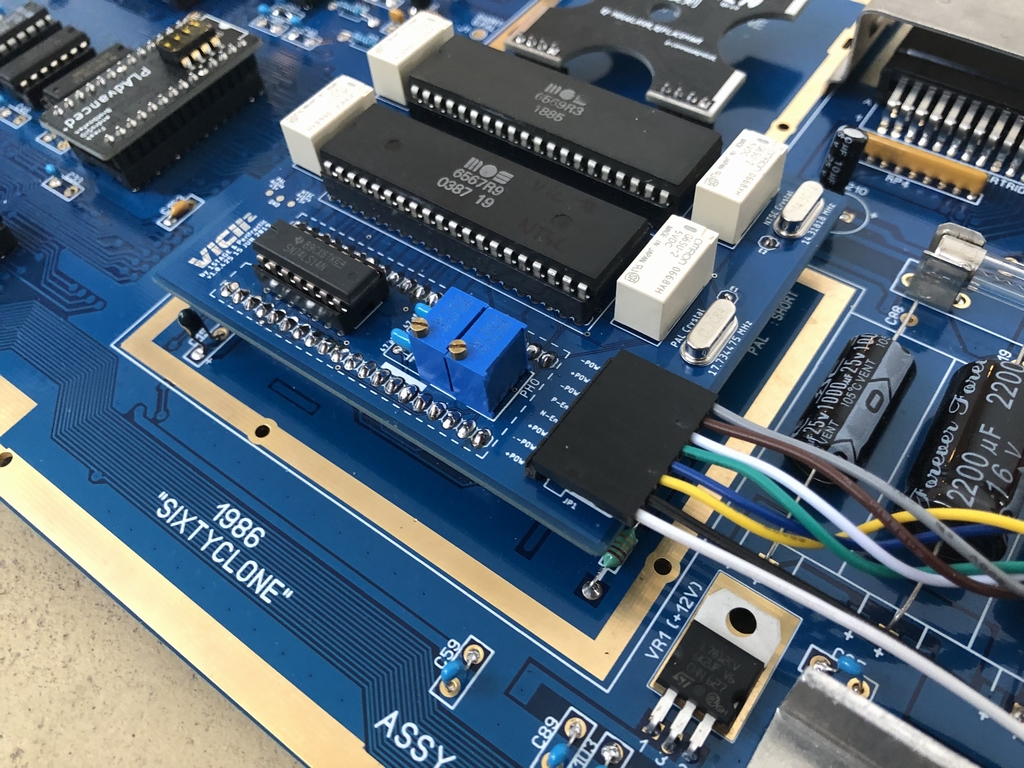
Below is a walk-through of how I build my version of the device. I used my Sixty Clone C64 Replica (link) board for the build. This is a replica of the orignal Assy 250466 longboard (link). This is what the The VIC-II² PAL/NTSC Switch looks like in a finished machine.
The Parts
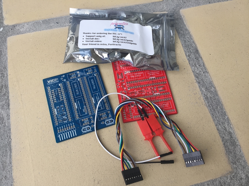
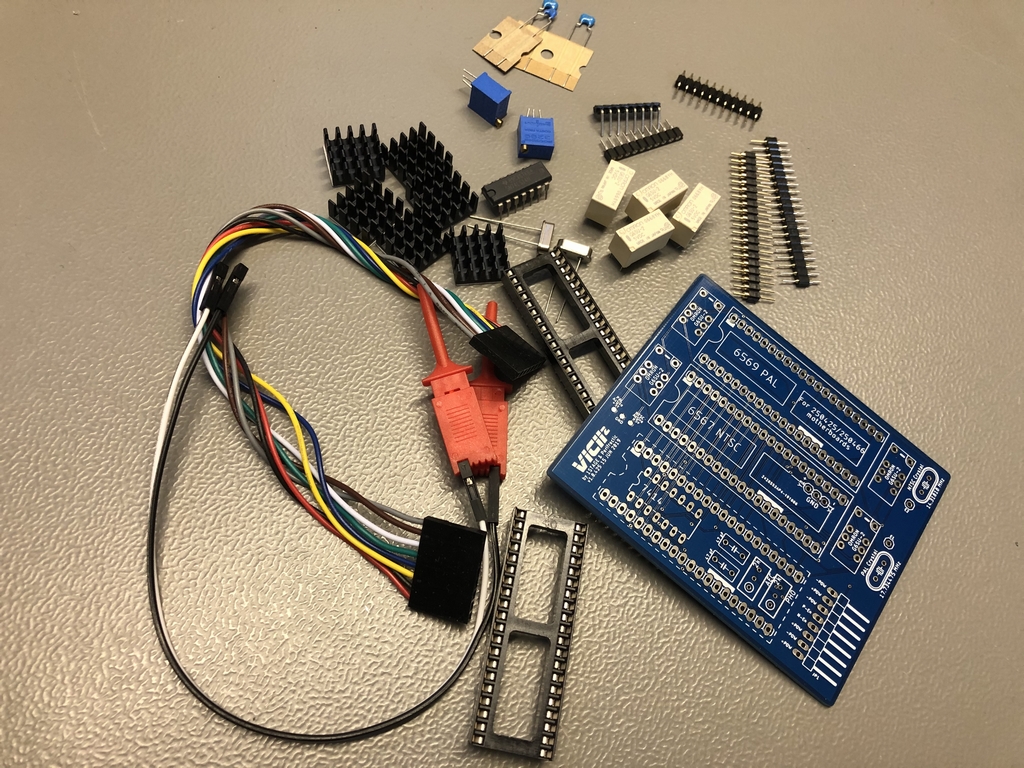
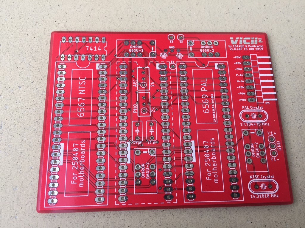
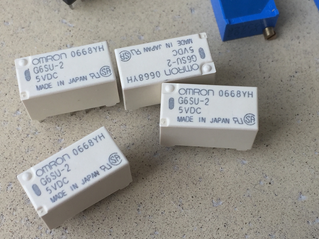
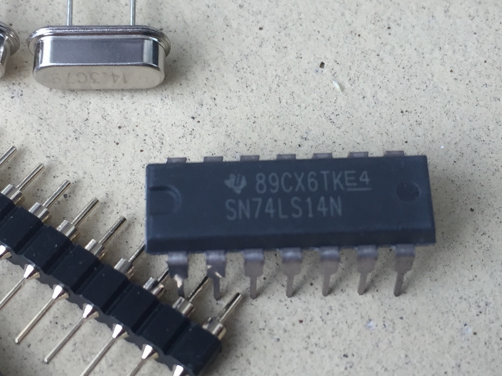
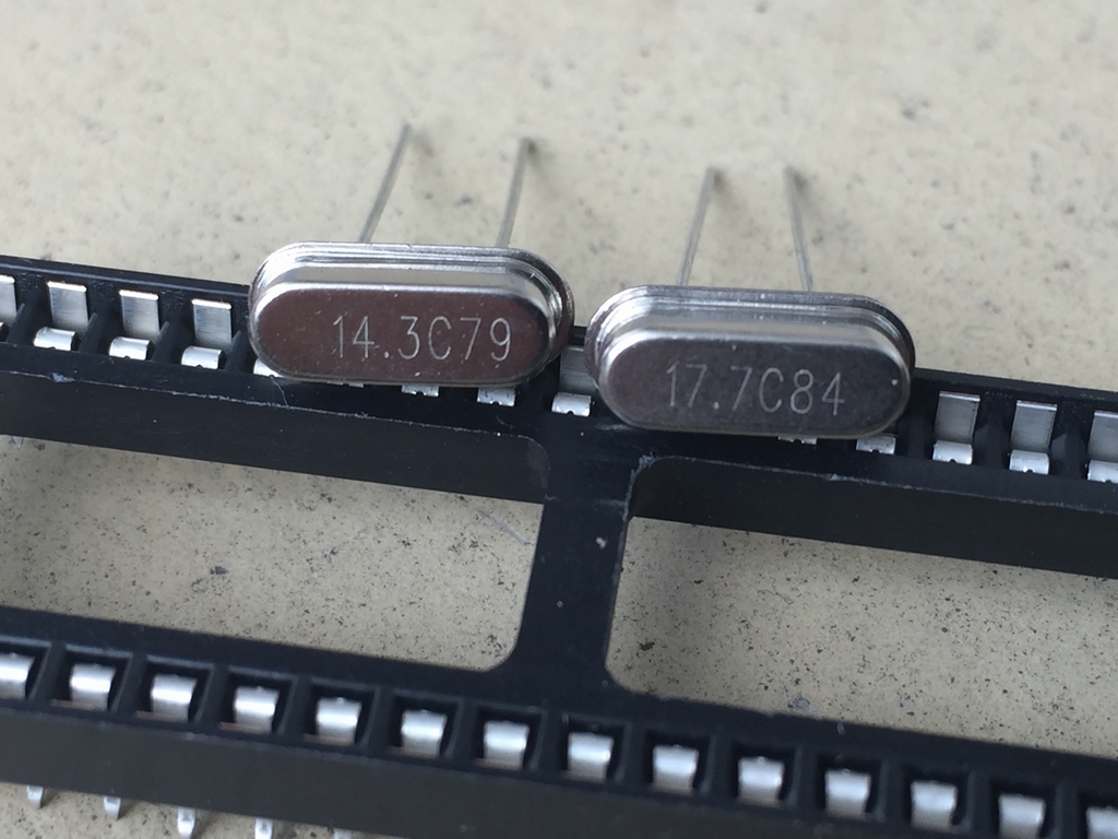
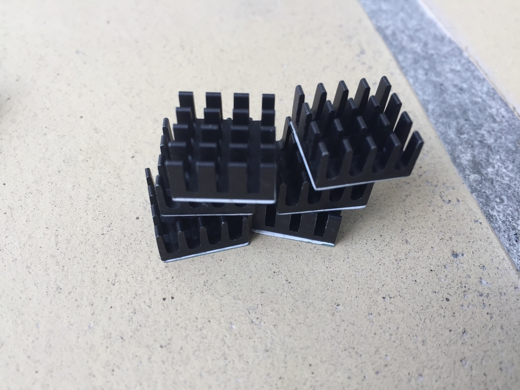
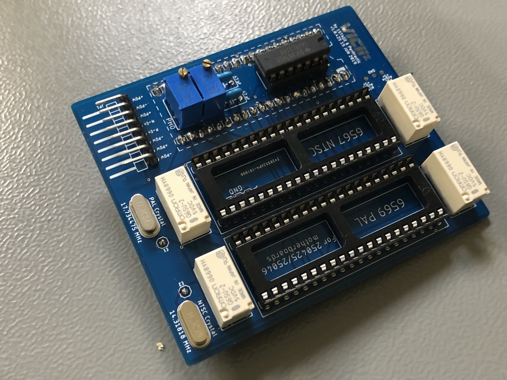
The parts came unassembled in a nice cardboard box with parts for both Assy 250407 (red PCB) and Assy 250425 & Assy 250466 (blue PCB) longboards. The VIC-II² PAL/NTSC Switch currently does not support the Assy 250469 short boards. The device consists of a PCB, sockets for the 6569 (PAL) and 6567 (NTSC) VIC-II video chips, timing crystals, 7414 inverter IC, cables, capacitors, trim resistors, relays and a heap of pin headers. It also came with some heat sinks. However, I never installed these eventhough they should prolong the lifespan of the VIC-II chips… Shame on me!
The Build
The installation manual can be found online in either video format (link) or as a document (link). The manual consists of mainly text, so I opted for the video version. It would have been nice with some images, but the video manual was really instructive and I did not run into any issues during the build.
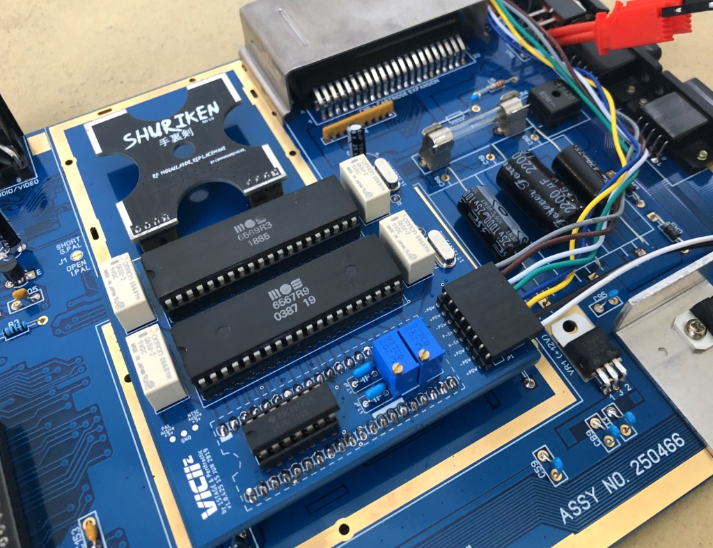
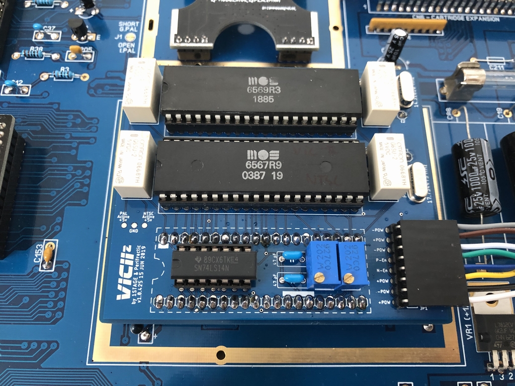
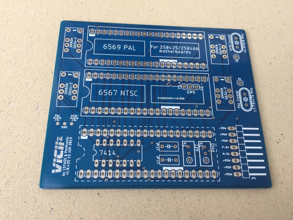
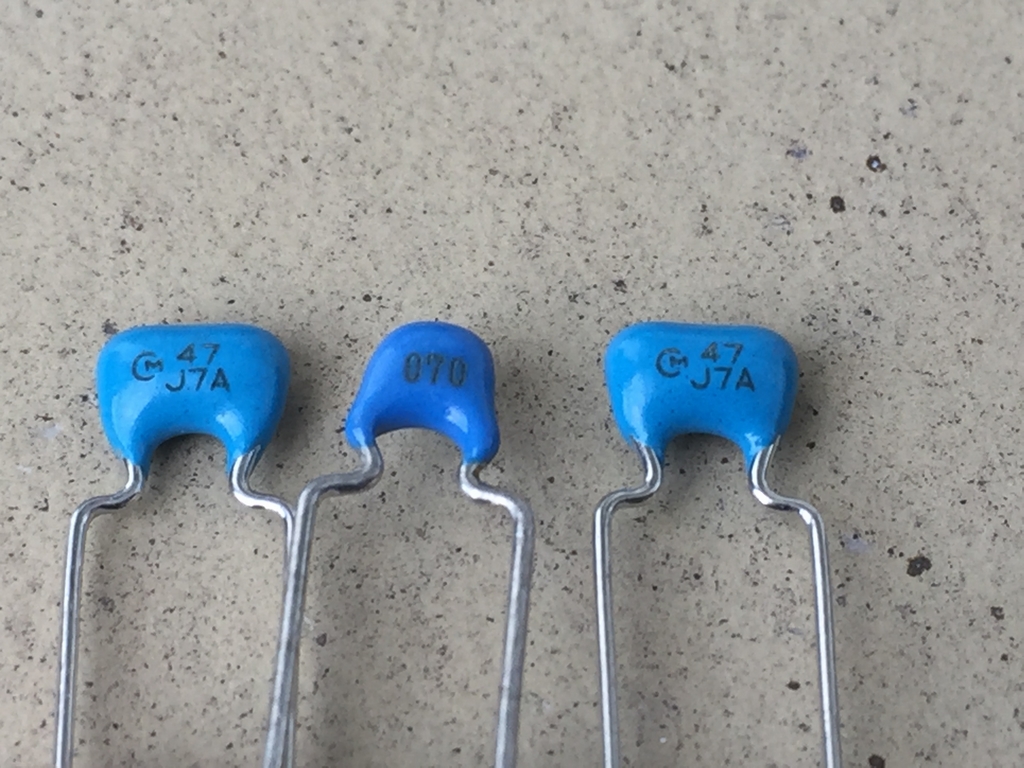
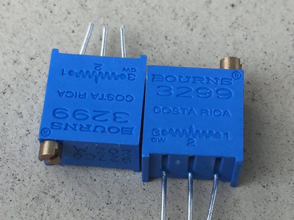
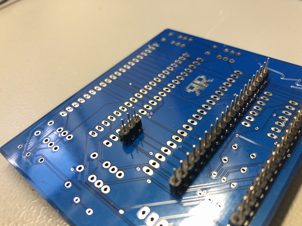
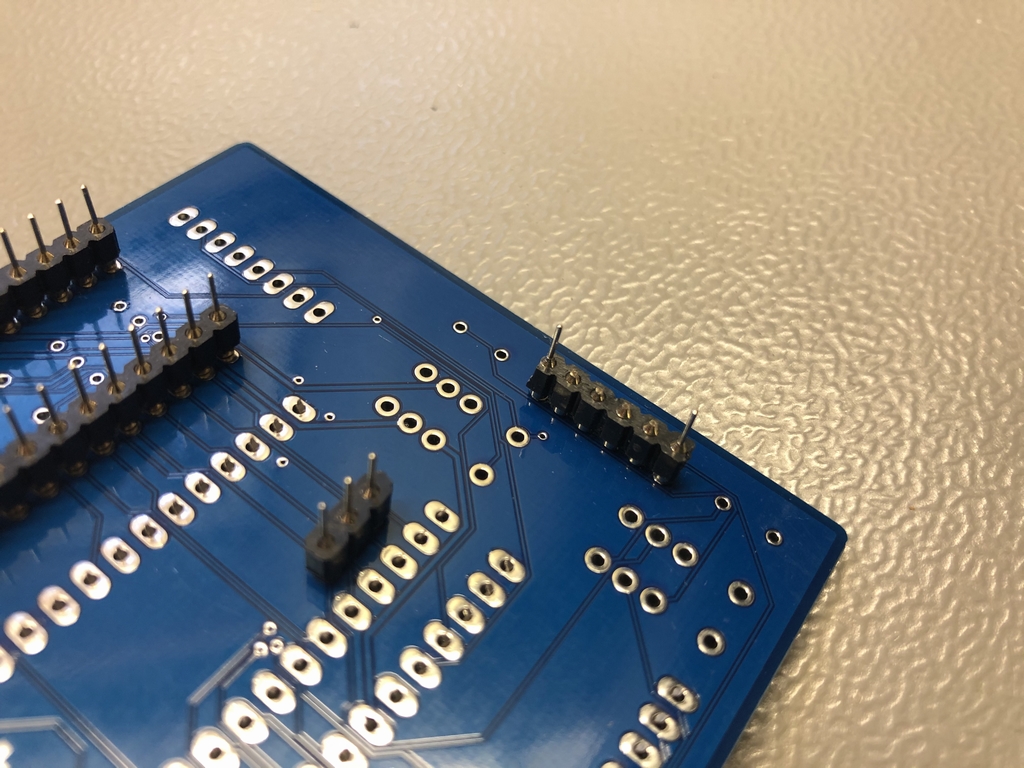
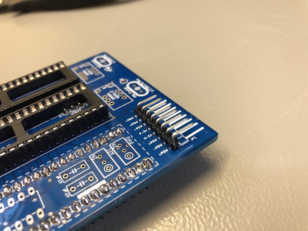
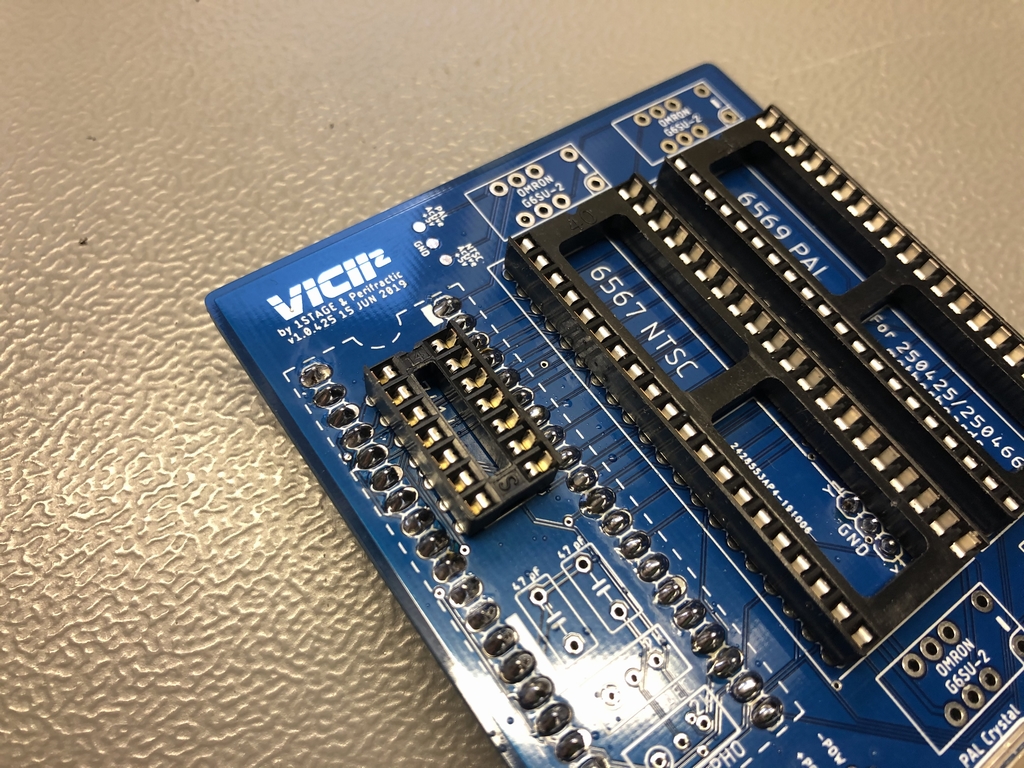
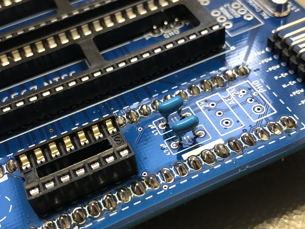
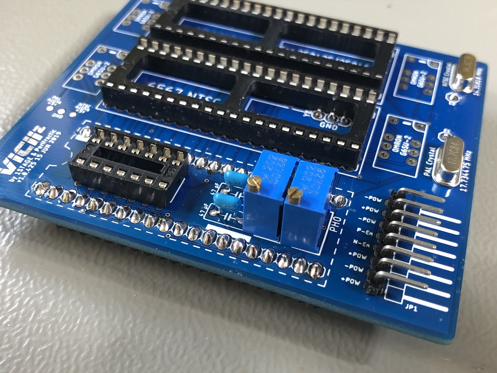
First up was soldering a heap of male pin headers. These are going to fit into the socket of the VIC-II chip, the timing crystal and the single lead PAL/NTSC jumper on the C64 motherboard. Then I installed the 90° pin header for the 8-pin rainbow cable. I finished off the build by installing the two timing crystals (PAL and NTSC), a socket for the 7414 inverter IC, the two 47 pF capacitors, the two trim resistors for the LumaFix64 and the four relays.
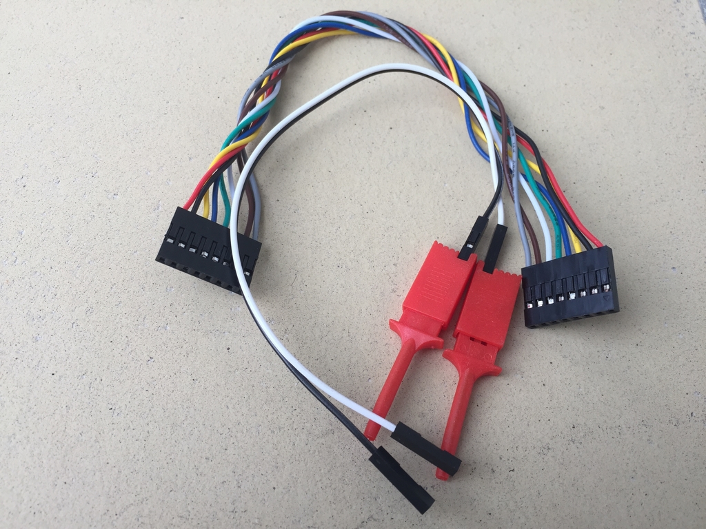
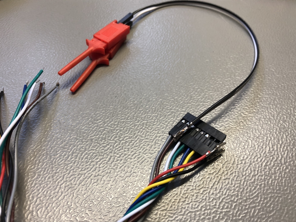
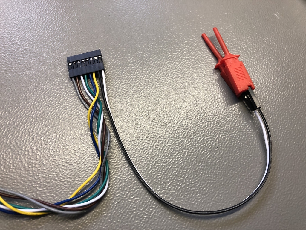
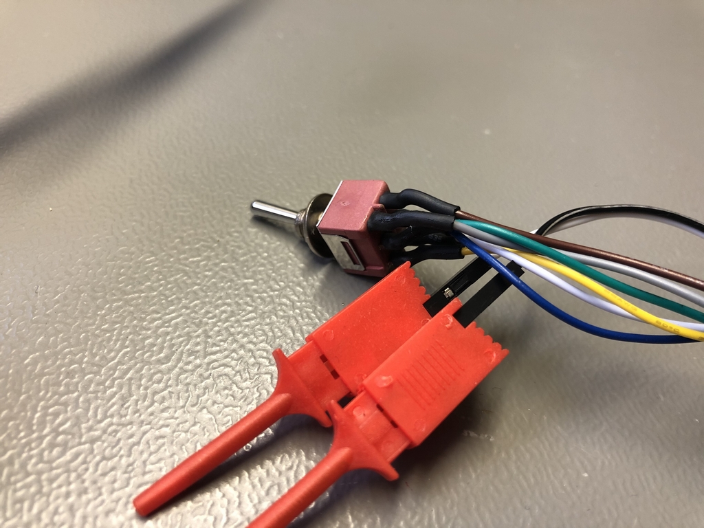
Next up was making the cables for powering the VIC-II² PAL/NTSC Switch and connecting it to the DPDT switch. The DPDT switch is needed for switching between PAL and NTSC output.
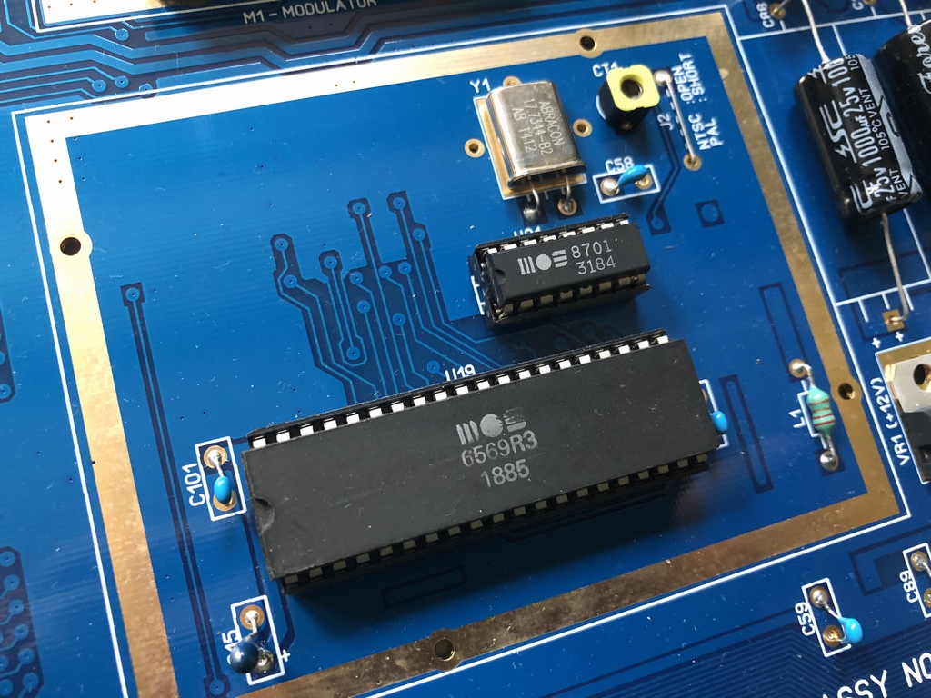
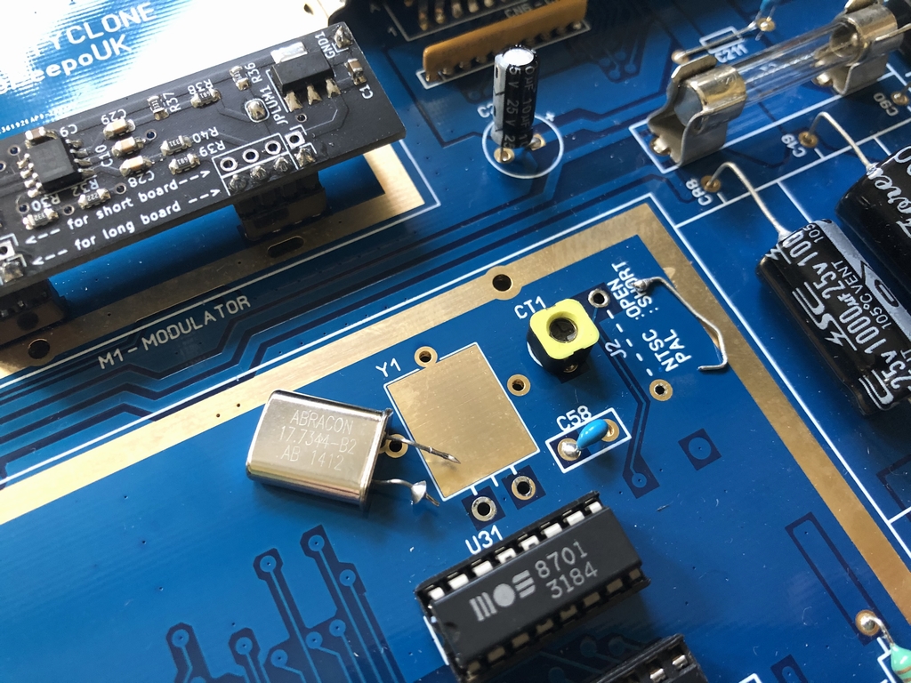
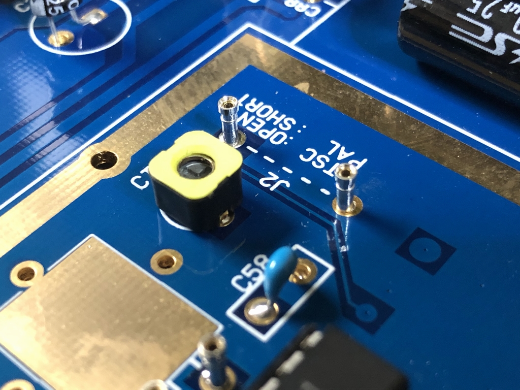
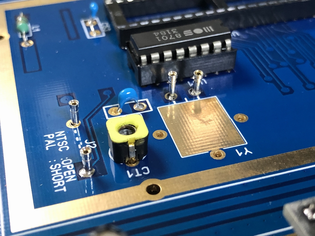
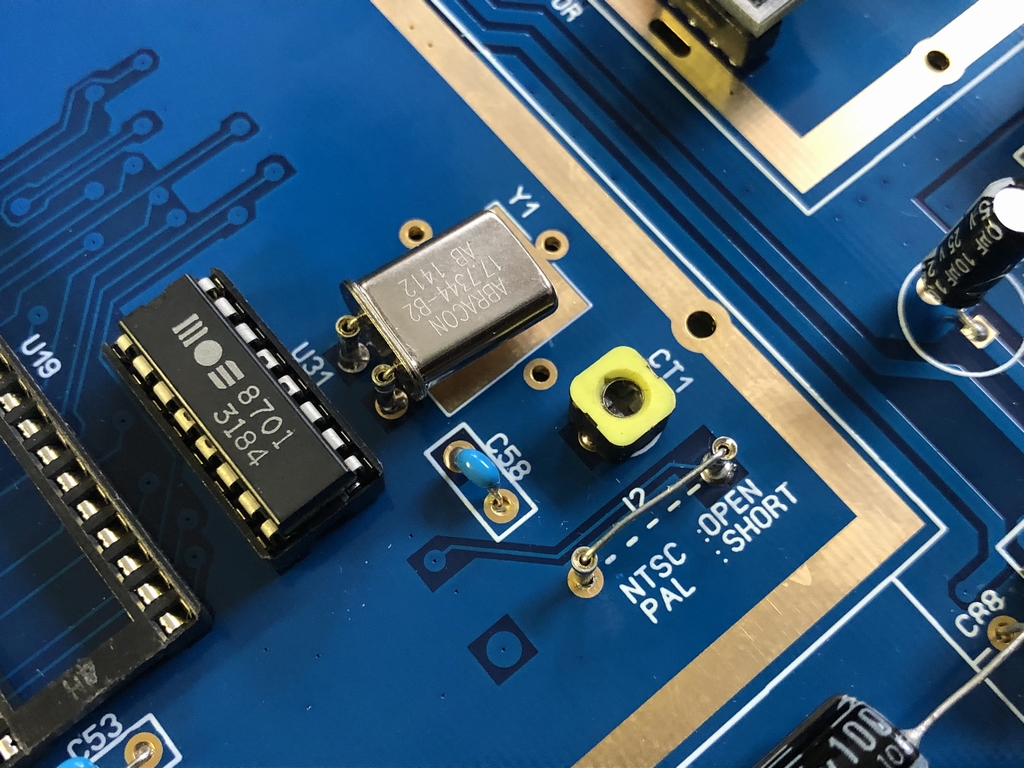
Finally, it was time to do the modifications to the longboard of the Commodore 64. The PAL timing crystal was unsoldered along with the PAL/NTSC jumper. I then installed some SIL sockets that the pin headers of the bottom of the VIC-II² PAL/NTSC Switch would fit into. This is Y1 and J2 on the motherboard. An easy way to make sure everything fits is to insert the SIL sockets into the male pin headers of the VIC-II² PAL/NTSC Switch and then mount the device before soldering the female SIL sockets to the C64 motherboard.
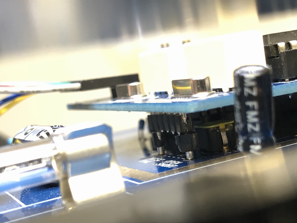
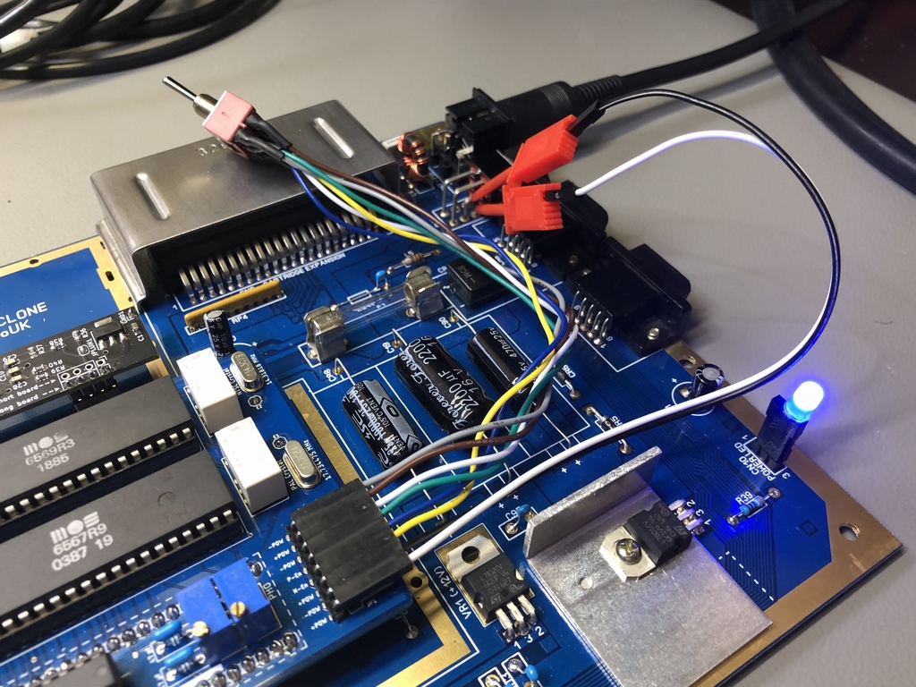
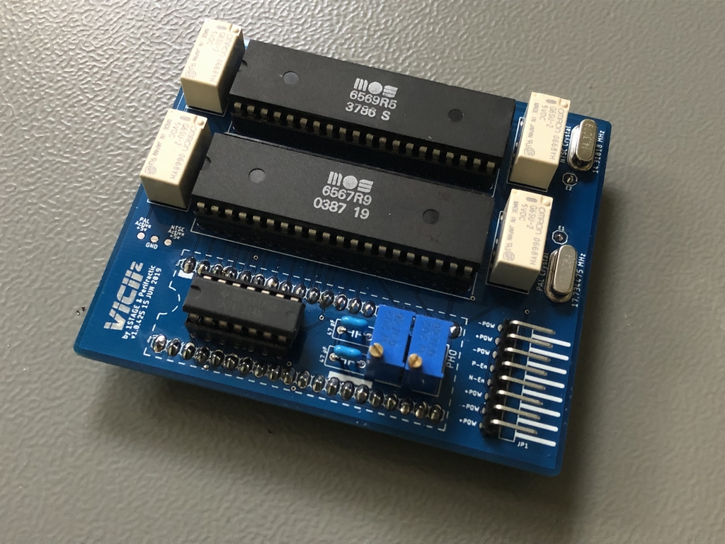
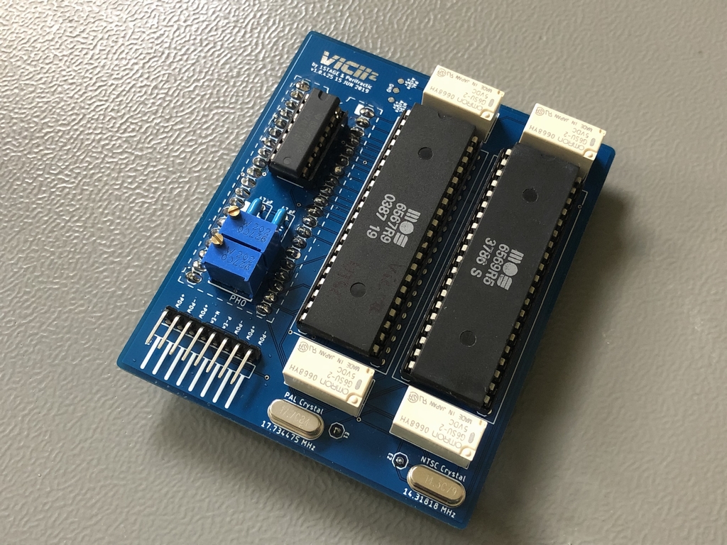
…and some images of the final build. The blue color of the VIC-II² PAL/NTSC Switch looks really nice on the Sixty Clone 64 250466 motherboard. The VIC-II² PAL/NTSC Switch gets power directly from the power switch of the C64 motherboard. This causes the VIC-II² PAL/NTSC Switch to receive 5 VDC for the relays before the Commodore 64 is turned on. In this context, the switching between PAL and NTSC can only be done when the power is turned off. Flicking the DPDT switch while the C64 is off will let you hear the realys click indicating that they are switching and working correctly. When the C64 is powered on, the relays cannot be operated hereby ensuring that the precious VIC-II chips are not fried! Safety first!
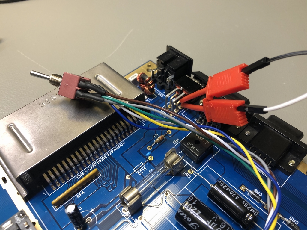
The video instructions use the Assy 250407 version of the device. I therefore used these instructions for placing the minigrabbers onto the power plug of the C64. As soon as the power plug went into the socket of the Commodore 64, the relays started rattling like crazy! Turns out that the Assy 250466 needs to draw 5 VDC from different pins of the power plug. When I figured that out, everything worked as it is supposed to. So please be careful when attaching the two minigrabbers!!
Due to the overall height of the VIC-II² PAL/NTSC Switch it can only be installed in a breadbox styled case and not in a C64C slim case like these (link).
Does it work?
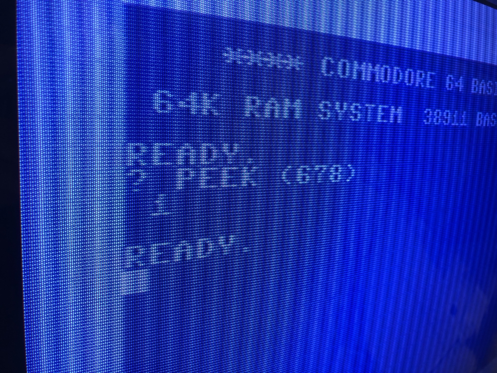
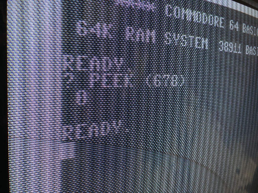
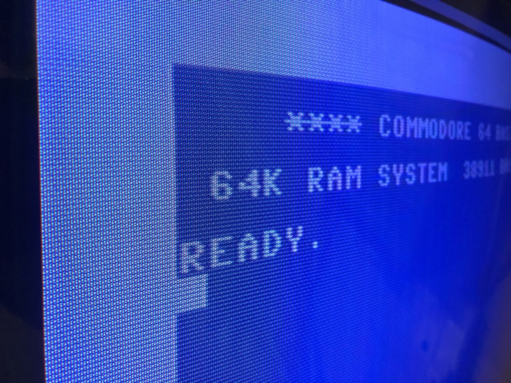
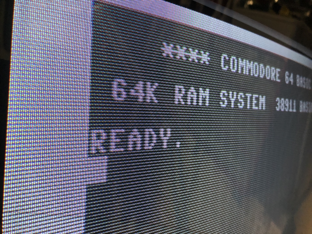
After turning on the Commodore 64 it showed the BASIC screen as expected. Writing ‘? PEEK (678)’ in the BASIC screen, the C64 will return either a ‘0’ for NTSC or a ‘1’ for PAL mode. As the LumaFix64 trim resistors (blue boxes with a small screw on top) were not adjusted yet, the images looked really horrible at first. After trimming everything, it was possible to remove almost all banding artifacts from the images. As my good old Bang & Olofsen mx4000 CRT TV does not support NTSC, the images were greyed out. If using an e.g. a HDMI upscaler and a modern-day flat screen TV, the images should look perfect regardless of what mode the C64 is in.
Final Thoughts
The VIC-II² PAL/NTSC Switch is a very nice product and it works as promised. It can swap between PAL and NTSC by the flick of a switch. Safety has been added so it is not possible to swap between modes when the motherboard is powered on. It should therefore be fairly safe for the delicate graphics chips and the rest of the motherboard to have the VIC-II² PAL/NTSC Switch installed. Furhermore, the device was quite easy to assemble and everything fitted as it was supposed to. One minor thing is that the written manual does not hold any pictures of the assembly. A manual with images would have made the build somewhat easier. I used the video instructions, which were fine, but they were of the PCB meant for the Assy 250407 longboards and not the Assy 250466 longboard used in this post. Nevertheless, it was not hard to ‘transfer’ the position of parts to one PCB to the other. So this is really no biggie 🙂
The quality of the parts are more than fine for a device like this. The price tag of 80 USD + shipping from the US may keep some people from buying the device. However, a product like this which is made in small quantities is obviously a little expensive. This product may therefore primarily be of special interest to Commodore 64 enthusiast living in a NTSC country. This is due to fact that most demos and games are made for PAL hardware. I myself live in a PAL country (with only PAL C64’s) and I have never needed to run a demo nor a game in NTSC mode. But that may just be me… Nevertheless, the device removes the need for having dedicated PAL and NTSC machines when running software with specific requirements. In that respect, the device is really a no-brainer as it saves costs of buying several machines. Congratulations 1stage and Perifractic on making a very nice and well-thought-out board. Well done guys 🙂
As a final note, if the VIC-II² PAL/NTSC Switch is no longer needed, it is really easy to swap everything back to whatever version it came from (PAL or NTSC). Simply use the SIL sockets to add the original timing crystal and the PAL/NTSC jumper to reverse the modifications needed for the VIC-II² PAL/NTSC Switch. Easy peasy…
© breadbox64.com 2020
Pretty pricey, indeed, for an unassembled kit of about $30 in parts and a cheap $2 chinese PCB. Also amusing to hear the maker claim it’s not “made for profit” at that price point on his youtube channel.
Great description – thanks for the insights. It’s still a lot easier to select between systems in the menu of an Ultimate64, but for validation on native hardware, this seems to be a great option.
And I still don’t understand why people investing time and taking financial risks developing stuff shouldn’t be allowed to make a profit. If you can do it cheaper then by all means do it. That’s what market economy is all about …