
Repairing broken Commodore 64’s is usually a matter of qualified guesswork and quite often substitution of chips is the only practical way to diagnose a fault. At least that is the approach I’m using when trying to resurrect broken machines. The challenge with this method is that most of the old C64 chips are in short supply (and insanely expensive to get online!). I therefore test possible broken chips in a machine that is known to be working. The problem with this approach is that sockets have to be installed throughout the test board to enable testing of all the different chips. In this context, ZIF (Zero Insertion Force) sockets may be used instead of standard sockets to reduce the risk of bending the pins when inserting and extracting chips. ZIF sockets function by moving a lever on the side of the socket which in turn pushes the socket contacts apart. This way an IC can be inserted with very little force and when the lever is moved back, the contacts close and grip the pins of the IC. Thus, insertion and removal of IC’s are effortless and reduces the risk of bending the pins.
In this mod I wanted to mount ZIF sockets to all the different chips on a Commodore 64 Version E (short board) motherboard for easy chip testing (link). Almost every chip on the board had a ZIF socket installed. Only two chips had a leaf socket installed due to space issues on the board. If two identical chips were present (like the CIA and RAM chips), only one chip had a new socket installed. To do the mod I ordered a stack of ZIF sockets on Ebay. I got green ZIF sockets from 3M and TFXTOOL in size 7.62 mm and 15.24 mm depending on the size of the chips they should accomodate.
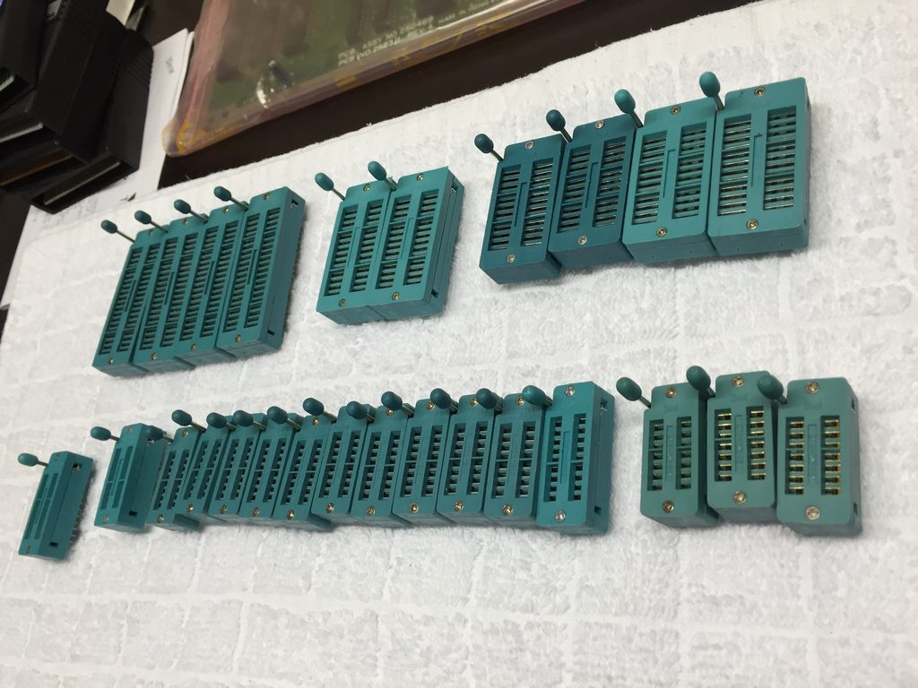
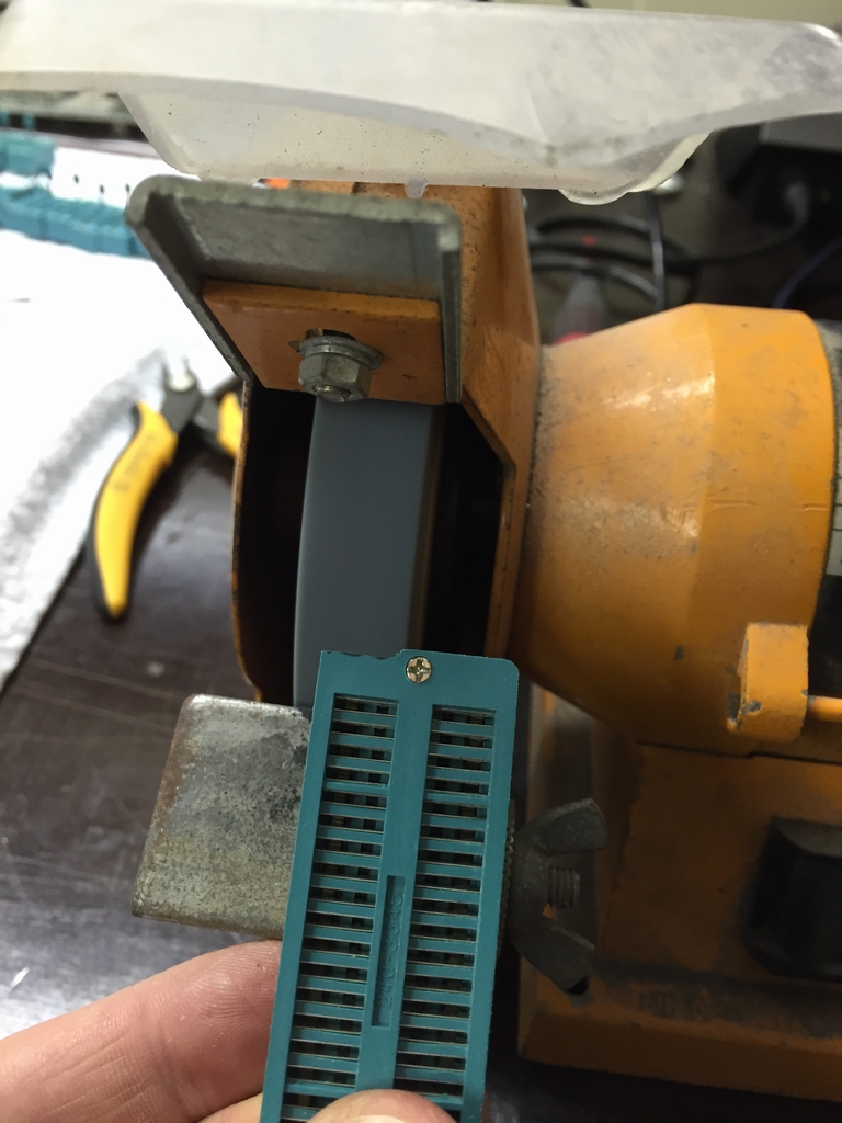
As evident from the picture above, ZIF sockets are bulky in design and not directly swappable on any Commodore 64 motherboard. Because of this, the mod took me quite a while as some ZIF sockets had to be turned 180° in order to fit, others had to have their levers bend a little and some even needed a little trimming to make them fit. The latter was pretty easy to do with the aid of my good old grinder!
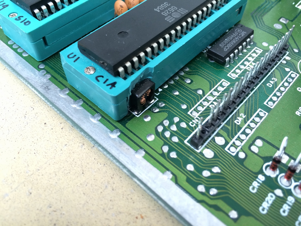
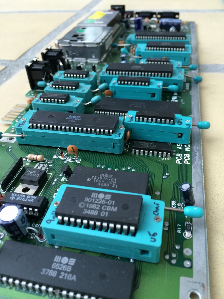
First up was the CIA (MOS 6526) at U1. The sides of the socket had to be trimmed to make room for the RF Choke Coils at L3 & L4.
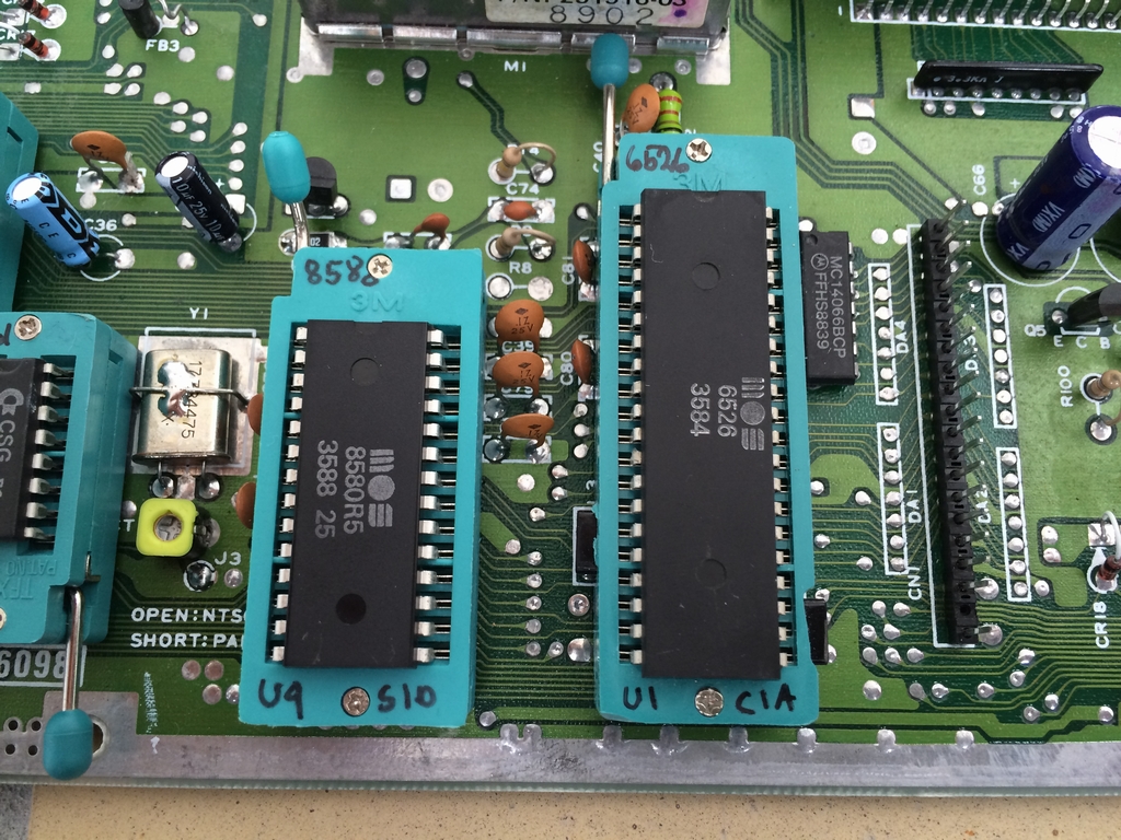
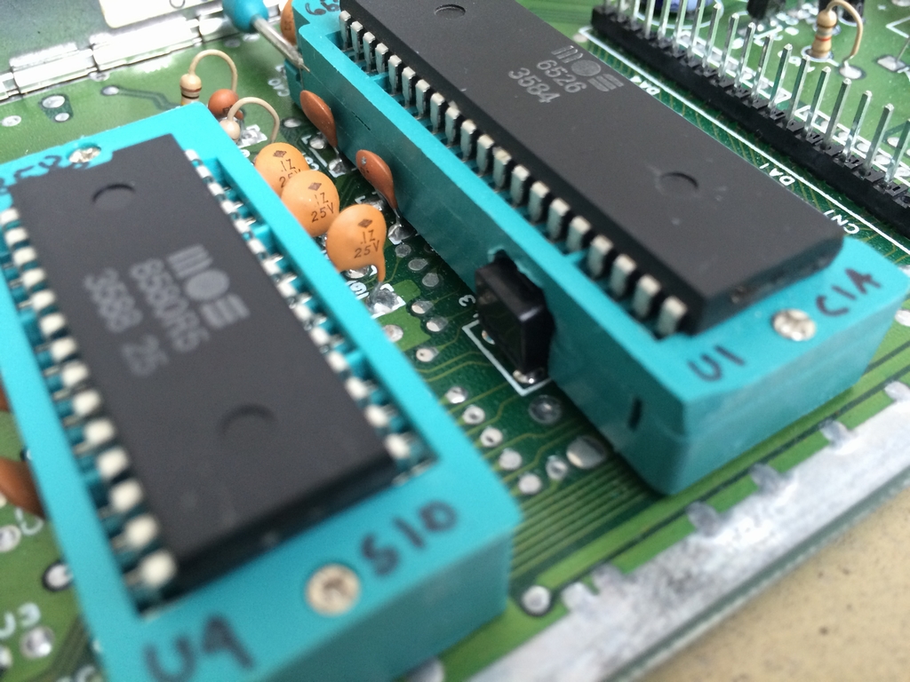
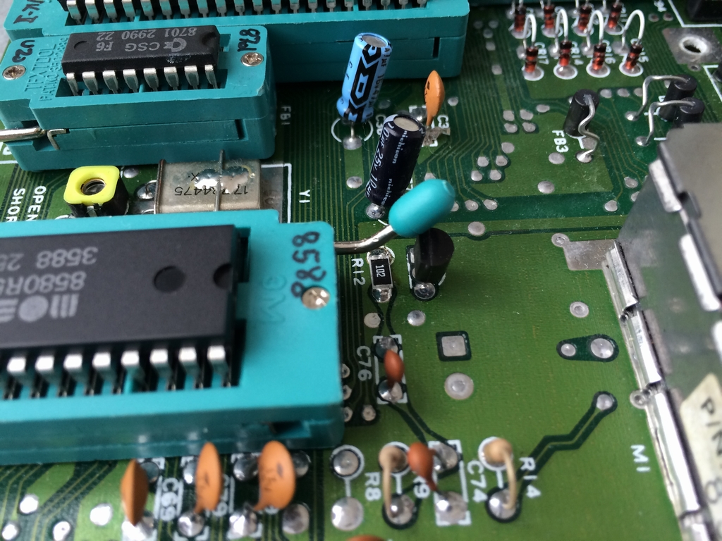
The lever on the SID (MOS 8580) chip ZIF socket had to be bend a little to stay clear of a transister. The 1 kΩ resistor at R12 was exchanged with a SMD (Surface Mount Device) type resistor to make room for the lever.
The VIC-II (MOS 8565) at U7 could pretty much be mounted without moving anything. However, to fit the socket for the 8701 clock generator at U20, the Ferrite Bead at FB1 and the capacitor at C35 both had to be moved to the backside of the board.
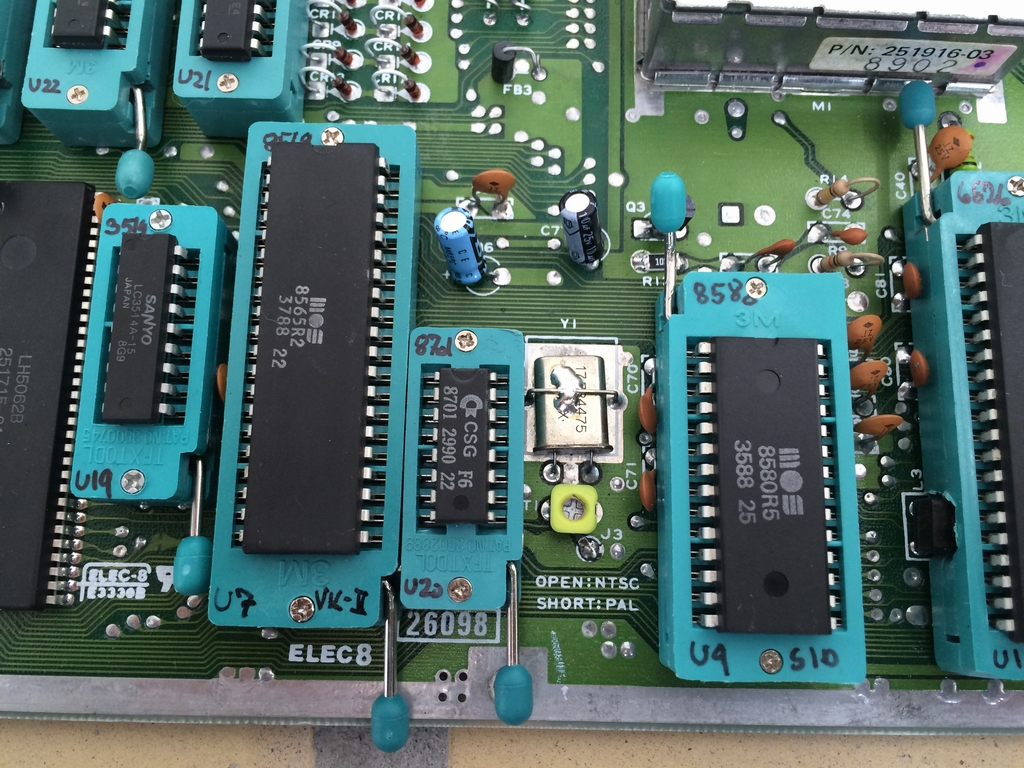
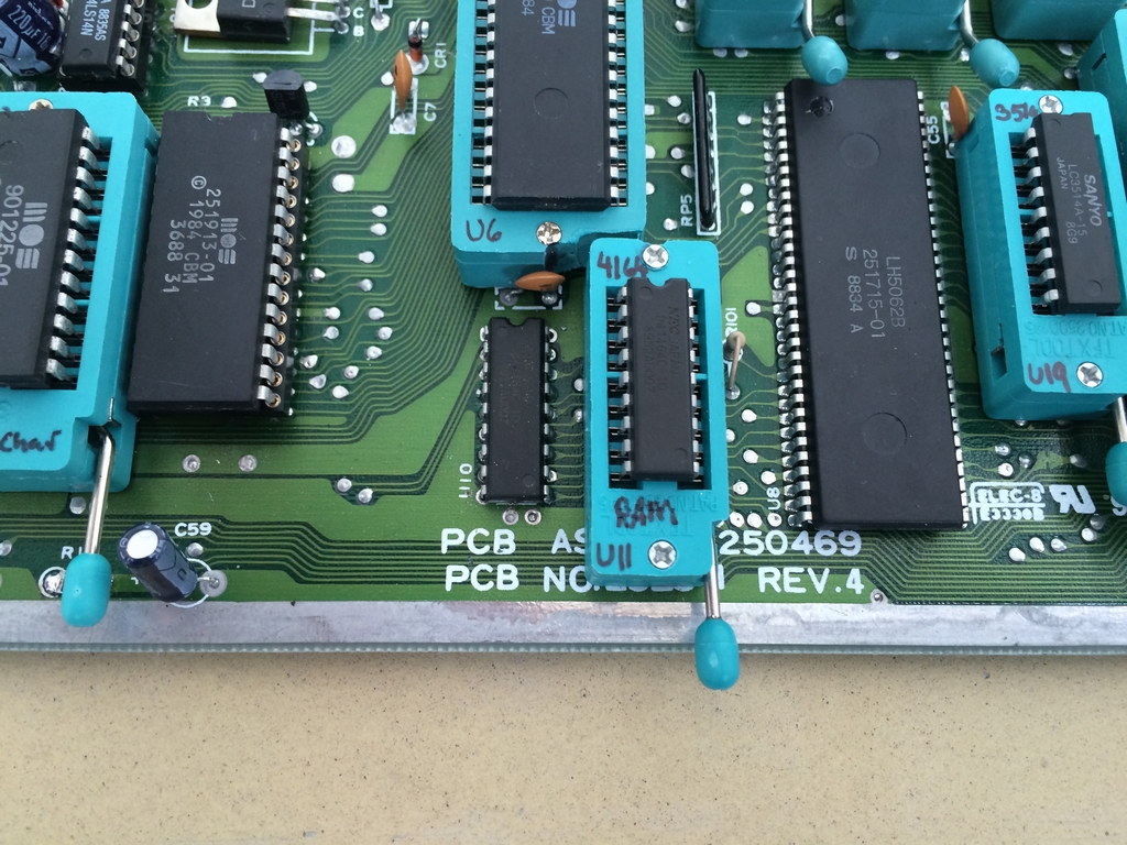
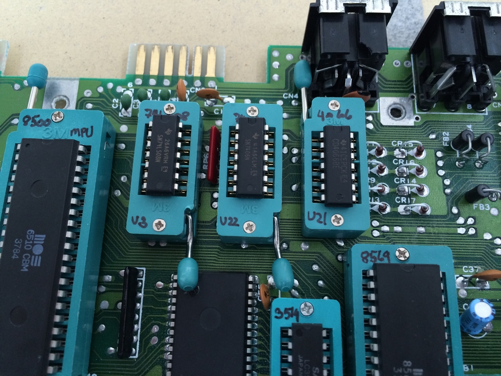
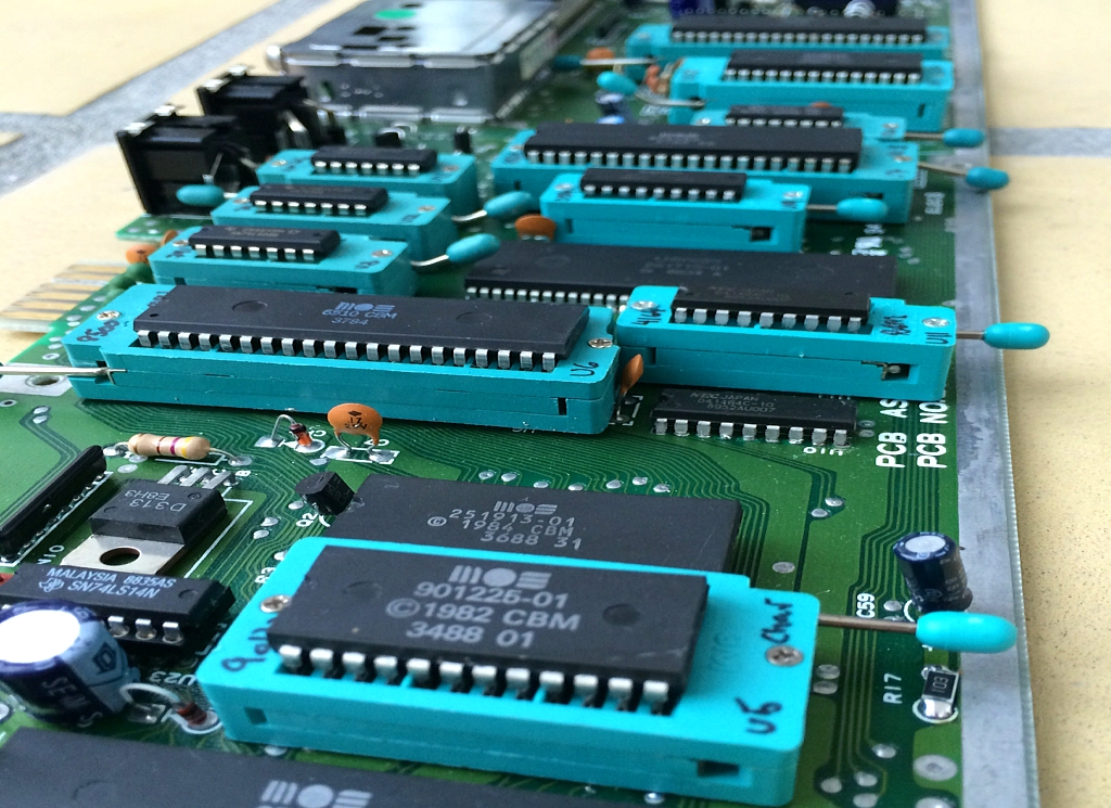
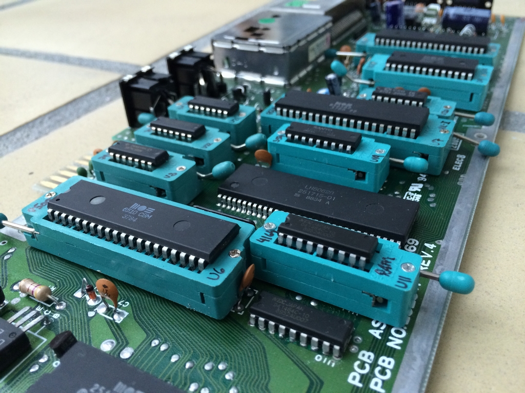
The RAM chip at U11 and the MPU (MOS 8500) at U6 were also swapped (a MOS 6510 IC was temporarily used for testing the board as I did not have a working MOS 8500 at the time of the mod). The sockets had to be trimmed a little to fit. The capacitor at C48, located in front of the RAM chip, had to moved to the backside of the motherboard.
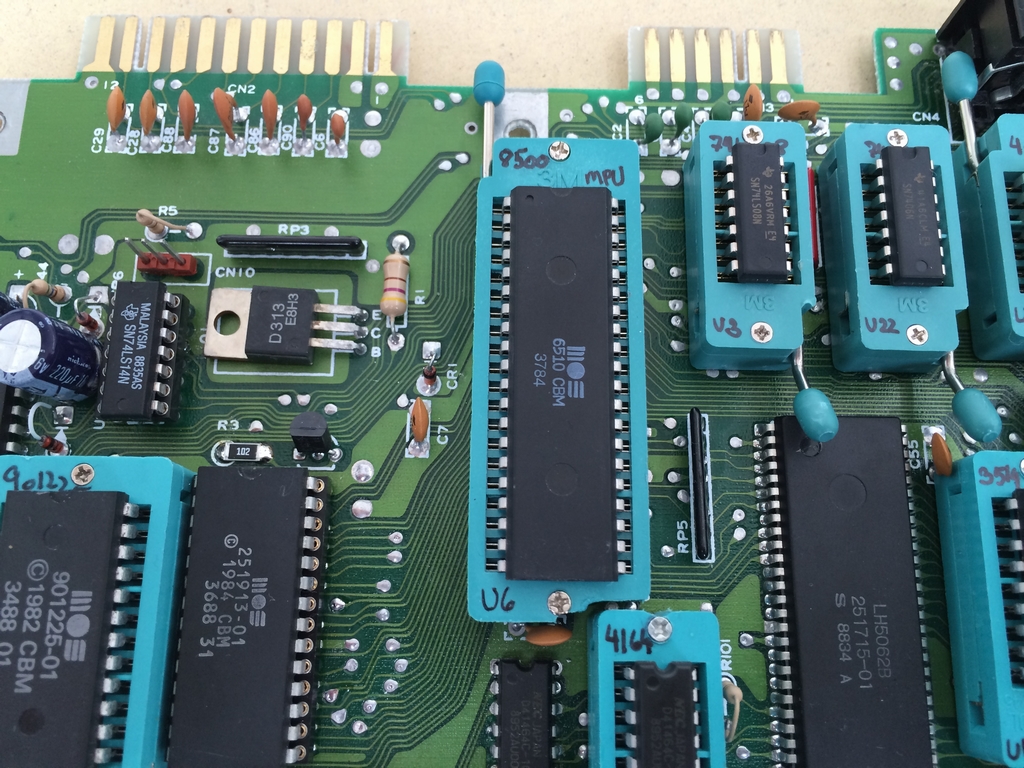

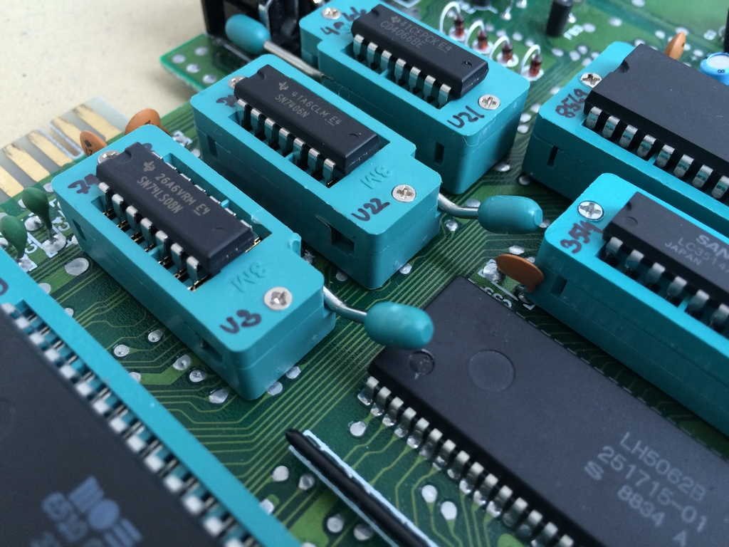
These three smaller chips (U3, U21, U22) also had ZIF sockets installed. The U3 and U22 levers had to be bend a little to stay clear of other components. The 4066 chips at U18 and U21 are identical. A ZIF socket was therefore only installed at U21 as there is more room on the board at this location.
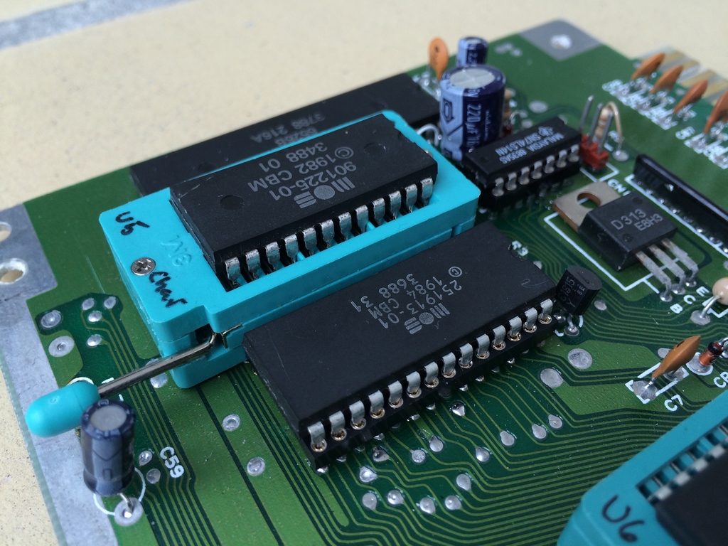
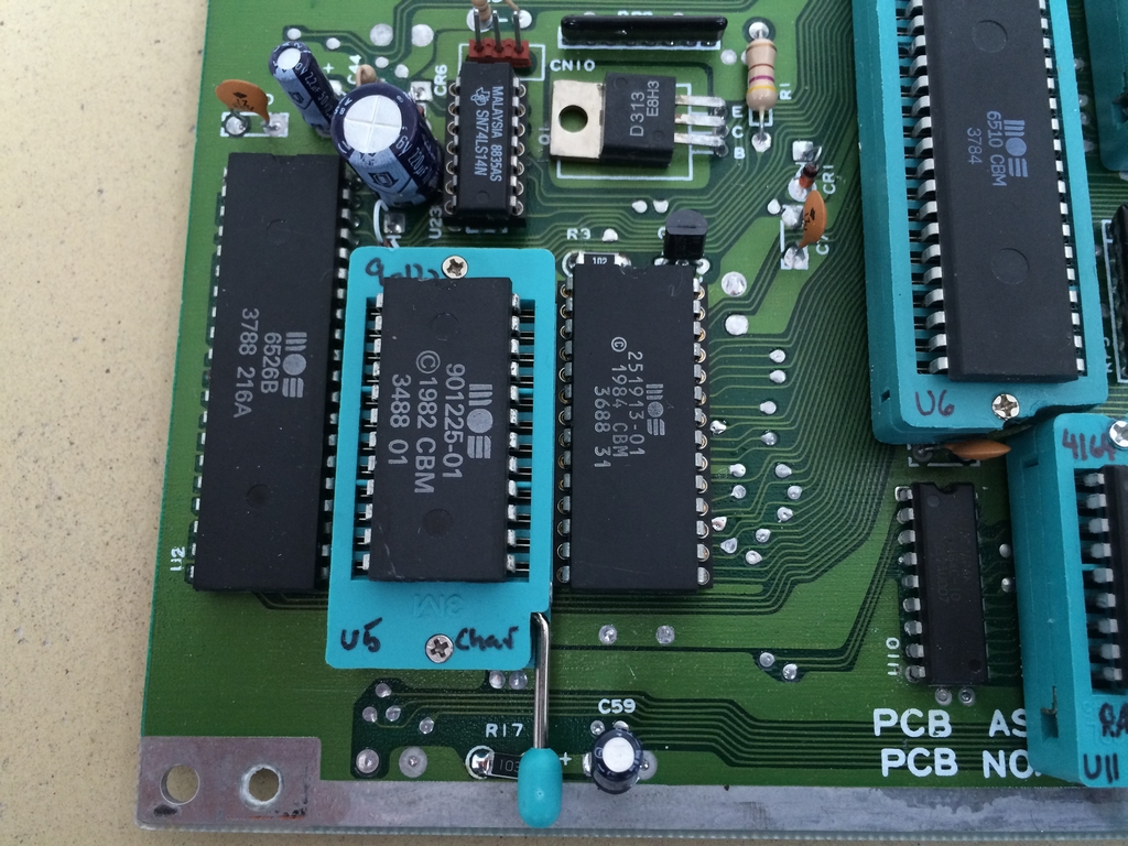
The Character ROM IC (MOS 901225-01) at U5 also had a new socket installed. The Basic and Kernal ROM IC (MOS 251913-01) at U4 and the 74LS14 chip at U23 both had leaf type sockets installed as there were no room for ZIF sockets. The two resistors (R3 and R17) were both replaced by SMD type resistors.
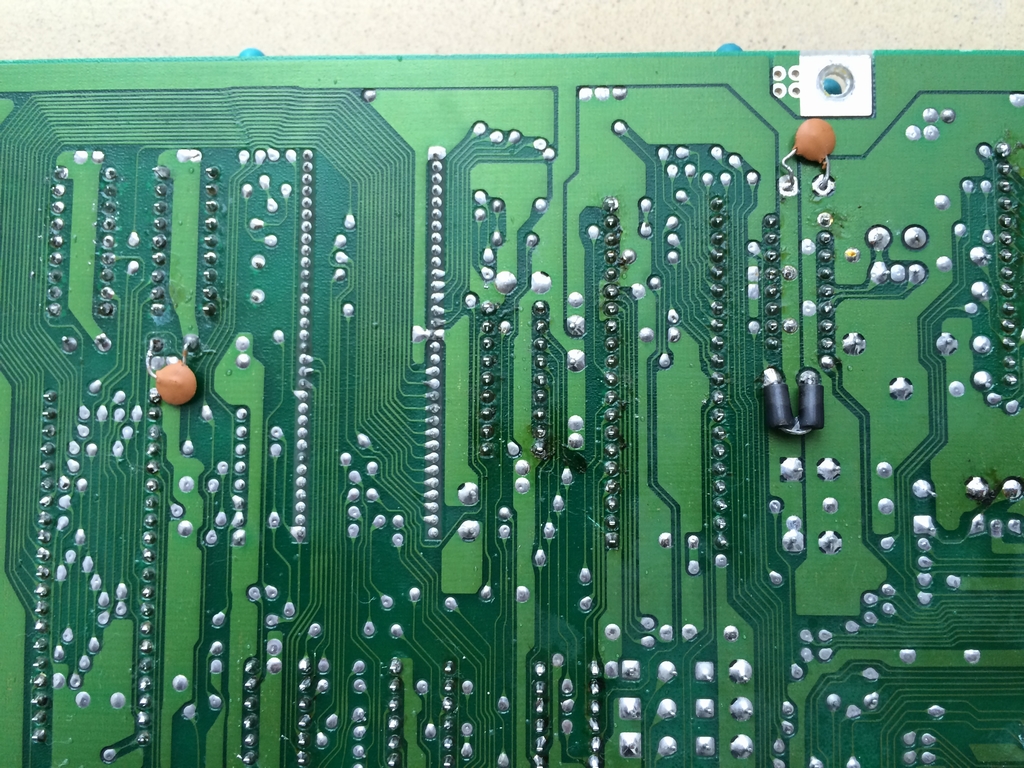
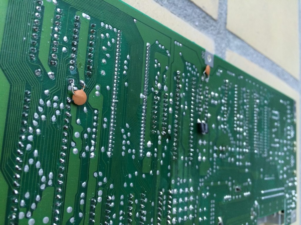
The back side of the motherboard with the few components that had to be removed from the upper side of the board. The components include two capacitors (C35 & C48) and the Ferite Bead (FB1). The components were flattened to make them fit when mounted in a case.
And finally some shots of the ZIF socket modded Assy 250469 Rev. 4 board.
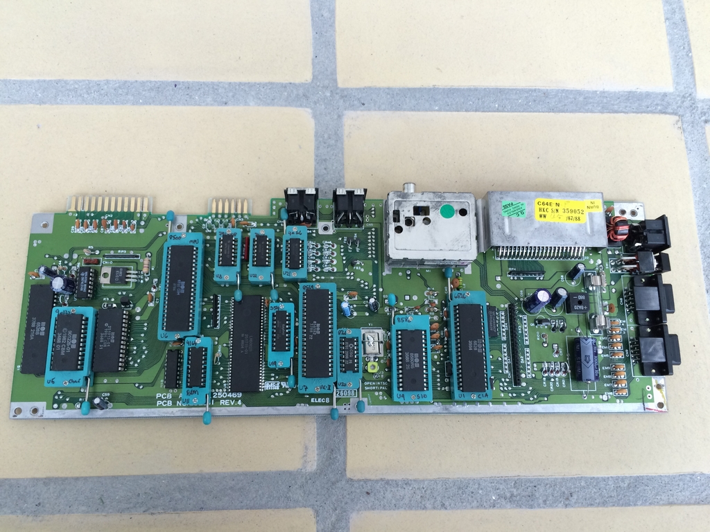
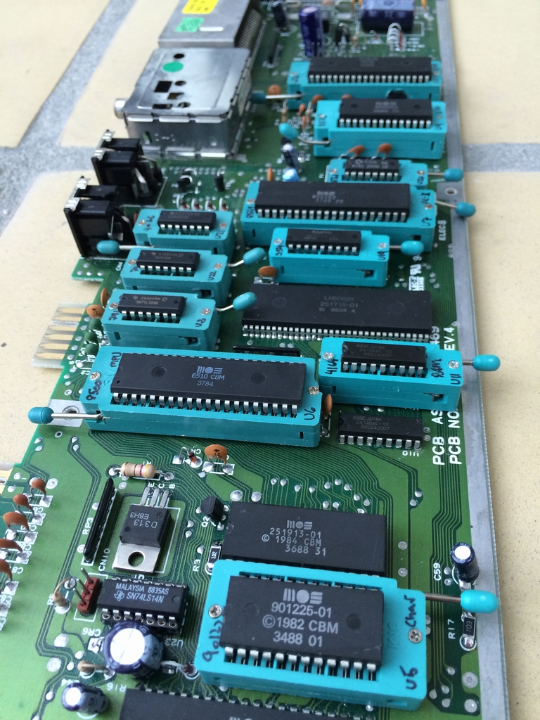
This board now serves as a my chip test board during repairs of broken Commodore 64 short boards.
© breadbox64.com 2016
Has anyone tried this on an Assy 469 board?
//C
The mod was actually made on an Assy 250469 short board 🙂 I don’t know if it has been done on one of the older long boards (Assy 250407, 250425, 250466). Would be a little harder as there are more chips on these boards. But I’m sure it could be done.
What’s the yellow thingy on the PAL/NTSC jumper pads? Some kind of switch I presume. Where did you get it?
It’s just a 7.7-40 pF capacitor/trimmer (CT-1) for trimming the video signal. The board came shipped with it, so it’s not something that I added to the board 🙂 All my C64’s have this trimmer, but it is only yellow on the 250469 boards.
I’m impressed you actually changed the resistors to SMD type resistors. I´ve never tried… I would need a finer tip for my soldering iron for a start. The wattage of it should be alright…
Thanks for the comment! He he… yes, I had to change the tip to a very fine one. I also used some pliers and a magnifying glass to do the soldering 🙂
This is such a great idea! Too bad the sockets are so bulky and other components leave not much space for them. I would make a test board for myself but I don’t have the means to properly modify the sockets.
A question about SuperPLA. Is there an existing ZIF socket for it…? I looked everywhere and seems that there isn’t a ZIF socket with a distanze of 19.05mm between pin rows.
Hi Stefano, I assume you mean the 251715-01 PLA for C64 short boards and not the SuperPLA made by Individualk Computers, right? If so, I have never seen a ZIF socket with 1.77mm distance and 19.05mm between rows 🙁
Hi! How could you put it on the motherboard? Because the ZIF sockets have legs larger than the hole in the motherboard. I would love to do it too, but for me it doesn’t go into it.
Hi Mortimer, I got the exact same question from another user a few weeks back. Truth is that I did not do anything to the socket pins. However, it took a little while to wiggle them into place 🙂 At least this holds true for the ZIF sockets I used. All sockets were from either 3M or TFXTOOL. They where not special versions or anything as far as I remember. Why you cannot make them fit I do not know – sorry 🙁
In the meantime, I realized I needed to clean the holes better, and then it goes into it. Thanks for the answer.
Happy to hear that you got it sorted out 🙂 Good luck with your project!
Heya, just popping in to say I’m impressed how many sockets you got to fit. I was looking at doing something similar to aid in testing. Does the lid still go on?
And also, if you got your sockets for a few dollars off eBay, they aren’t 3M Textool – they’re clones that likely have 1u” gold instead of 30u” gold. Real ones are $20+ from distributors (Mouser etc). The clones still take thousands of insertions to wear out (I wore out the clone one in my TL866 and had to replace the socket).
And the ZIF socket for the MMU should be part number 264-1300-00-0602J ($40). I can also see clones of it on Aliexpress for $9.