
Primarily for nostalgic reasons, I still keep a few 5.25″ floopies in my collection. However, there are so many other ways to handle Commodore 64 programs and games than having to fiddle around with old diskettes. One of these devices is the SD2IEC which I have described a few time already (link, link). The SD2IEC is a mass storage solution that uses a SD card for data storage (e.g. games and programs) and interfaces with the IEC bus of the Commodore 64. It does not emulate the 1541 diskette drive completely like the 1541 Ultimate II (link), but it reads quite a few .d64 and .prg files and it supports JiffyDOS natively (link)! In this context, 16×8 Digital Retrovation (link) (UPDATE: the device is now being sold by Heimes-elektronik.de) has made a neat little SD2IEC device that is intended for an internal installation. The device costs 25 Euro (≈27$) + shipping from Germany.
The SD2IEC Mini Device:
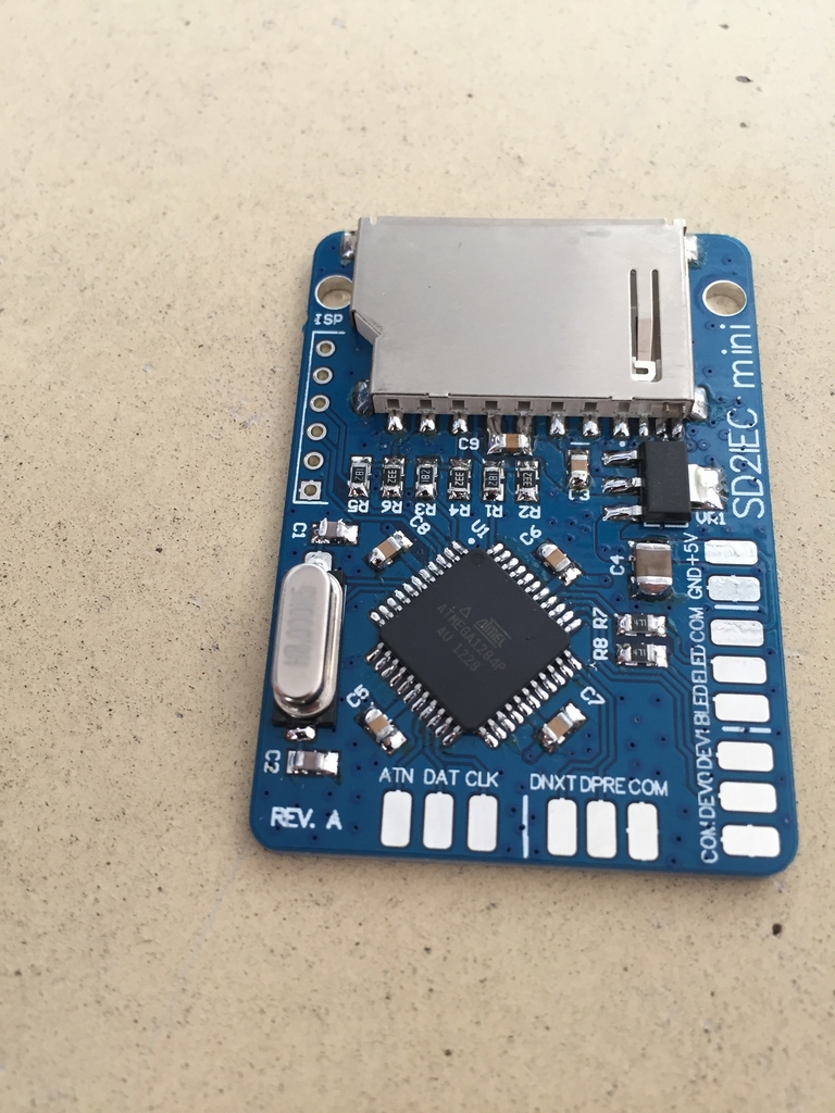
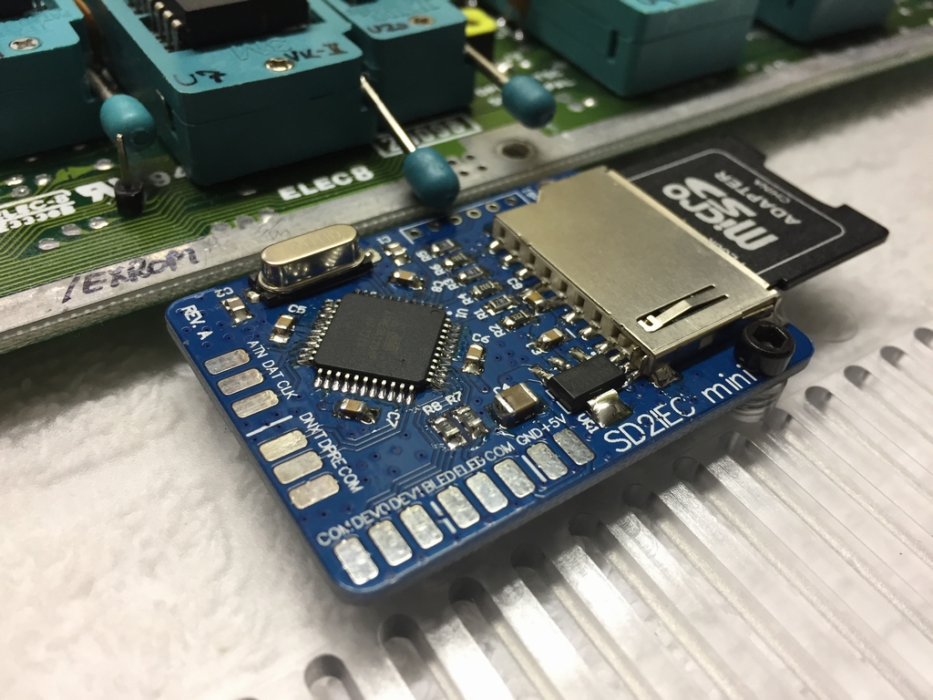
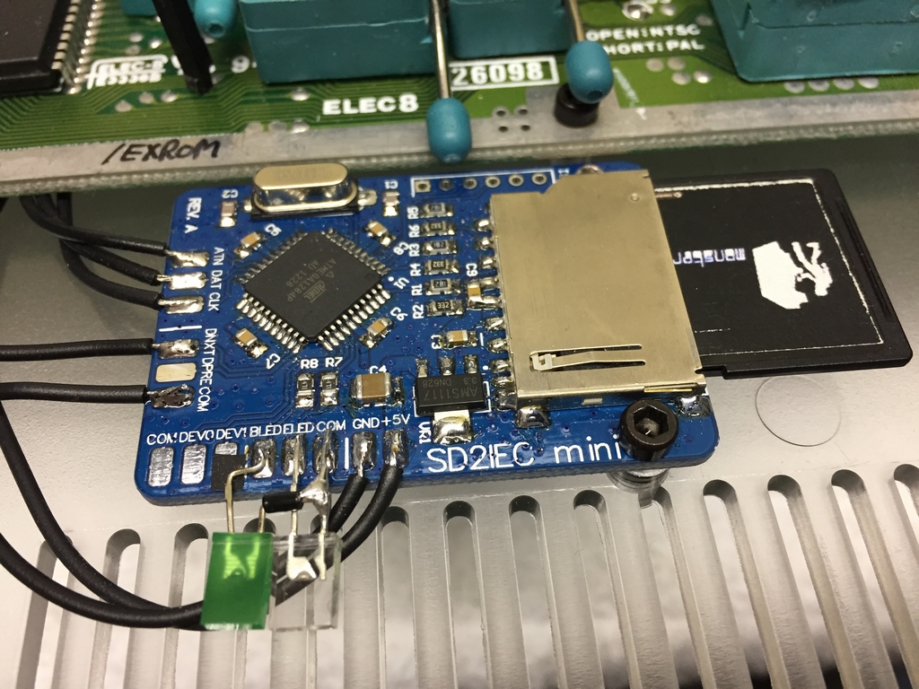
This is what you get when ordering the device. One must supply cables and momentary push buttons for the installation. I really like the simplicity of the SD2IEC Mini and the color is sweet!!!
Installation:
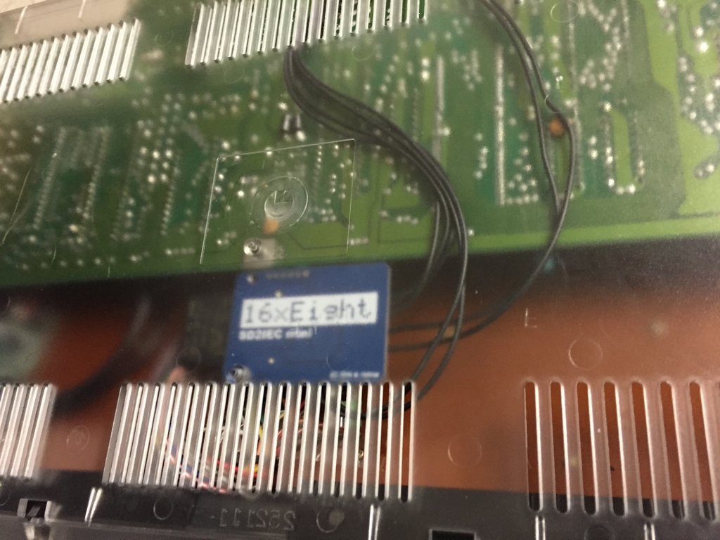
The SD2IEC Mini has solder pads for the cable connections with instructive labels on them, so it should be (well, almost…) possible to mount it without a manual (which is only in German by the way…). I mounted it in a transparent Kickstarter case (link) below the motherboard (Assy 250469) using one of the case mounting holes. As I wanted it to be a completely internal installation and the device is really small (35 x 50 x 5 mm), I only used a single self tapping screw to fasten it.

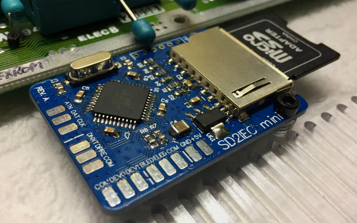
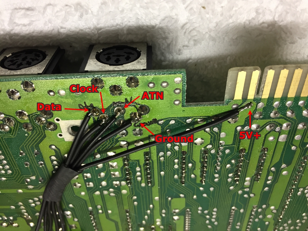
The SD2IEC Mini must be soldered to the 5V+, Data, CLK, ATN and Ground lines of the IEC (Serial Port). This can be achieved using these soldering points on an Assy 250469 short board.
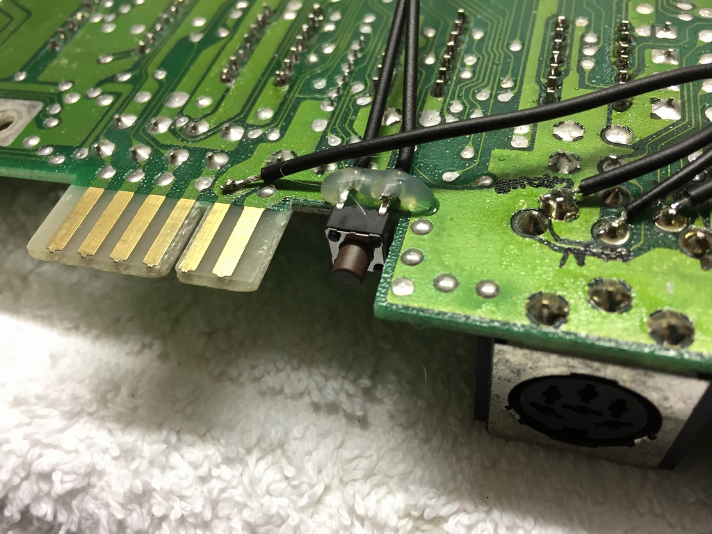
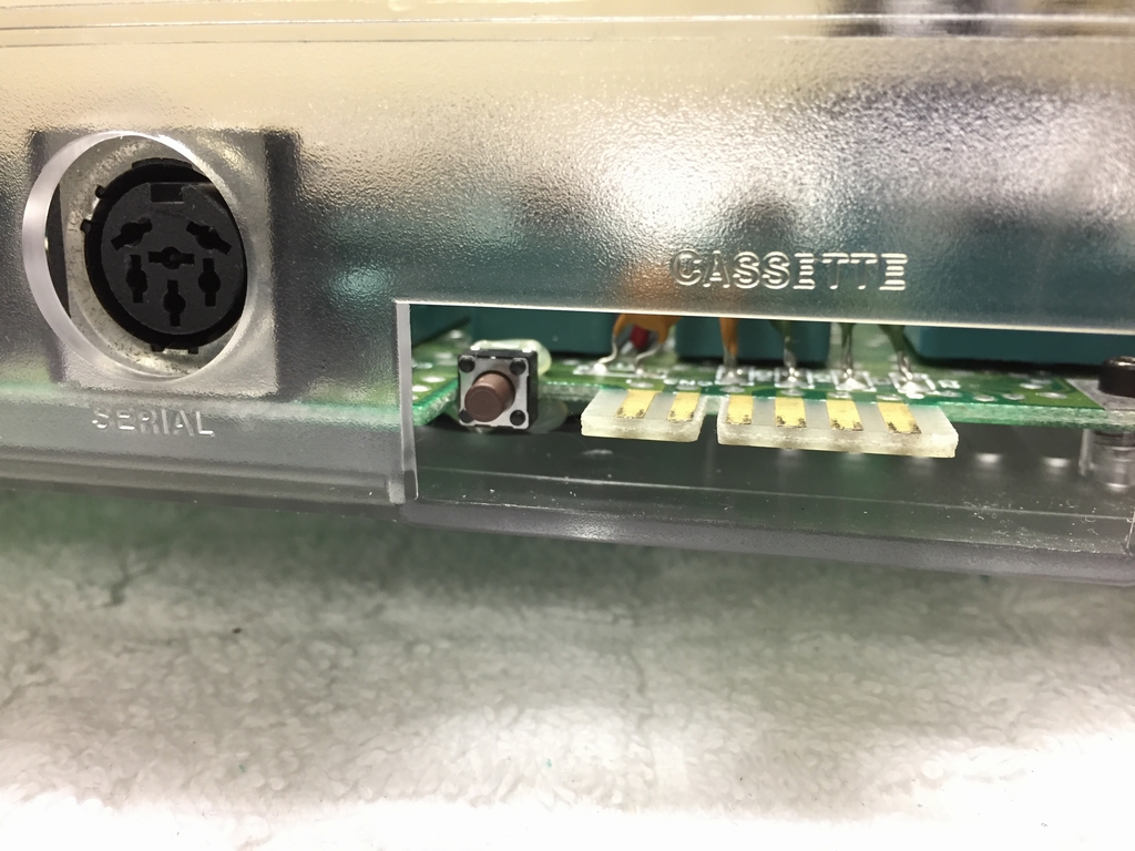
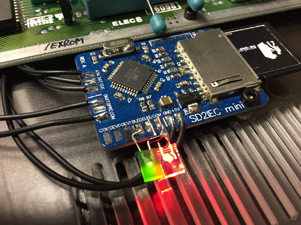
The SD2IEC mini has options for disk swapping (next and previous disk) using momentary push buttons for multi-sided games. To keep the installation as simple as possible, only one push button was installed for changing to the next disk. Some hot glue was used to fasten the button to the cassette port and it can easily be pushed by using a finger.
Next up was the LED’s for indicating disk load errors (red) and disk activity (green). And of course soldering all the cables to the device.
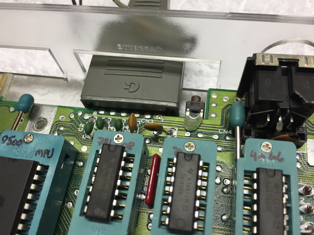
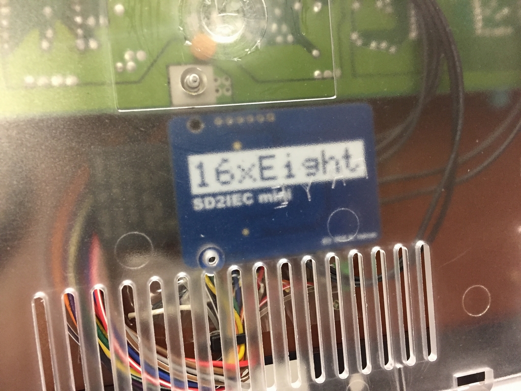
This is how the device looks inside the transparent Kickstarter Commodore 64 C case. If more programs or games are to be added, the case has to taken apart to gain acccess to the SD card. This is clearly unhandy if done on a regular basis 🙁 However, as I rarely change the content of the SD card, this is not going to be an issue for me.
Configuration:
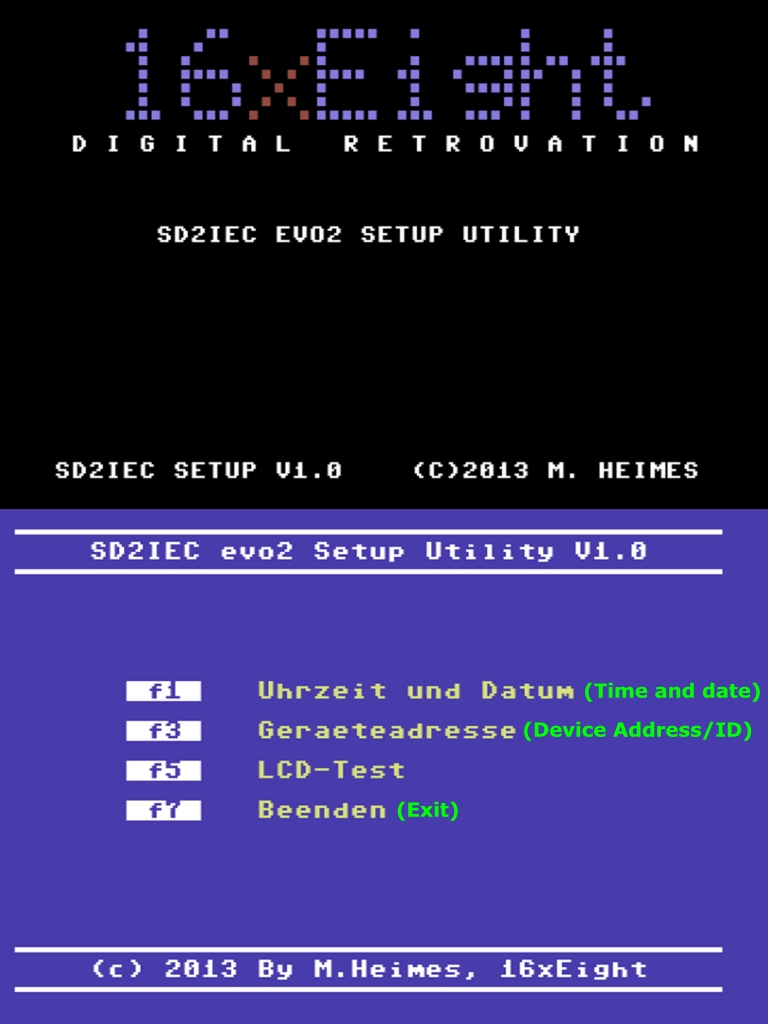
The device number of the SD2IEC Mini can be changed using a small software tool that is available from the website. This is handy if multiple IEC devices are connected to the Commodore 64 simultaneously (e.g. the 1541 Ultimate II or an original Commodore 1541 Diskette drive, link). The configuration tool is directed towards the advanced SD2IEC EVO2 (which is also sold by 16×8 Digital Retrovation), so it can only be used for changing the device ID on the SD2IEC Mini. The tool has German writings, so I have tarnslated the non-self-explanatory parts 🙂
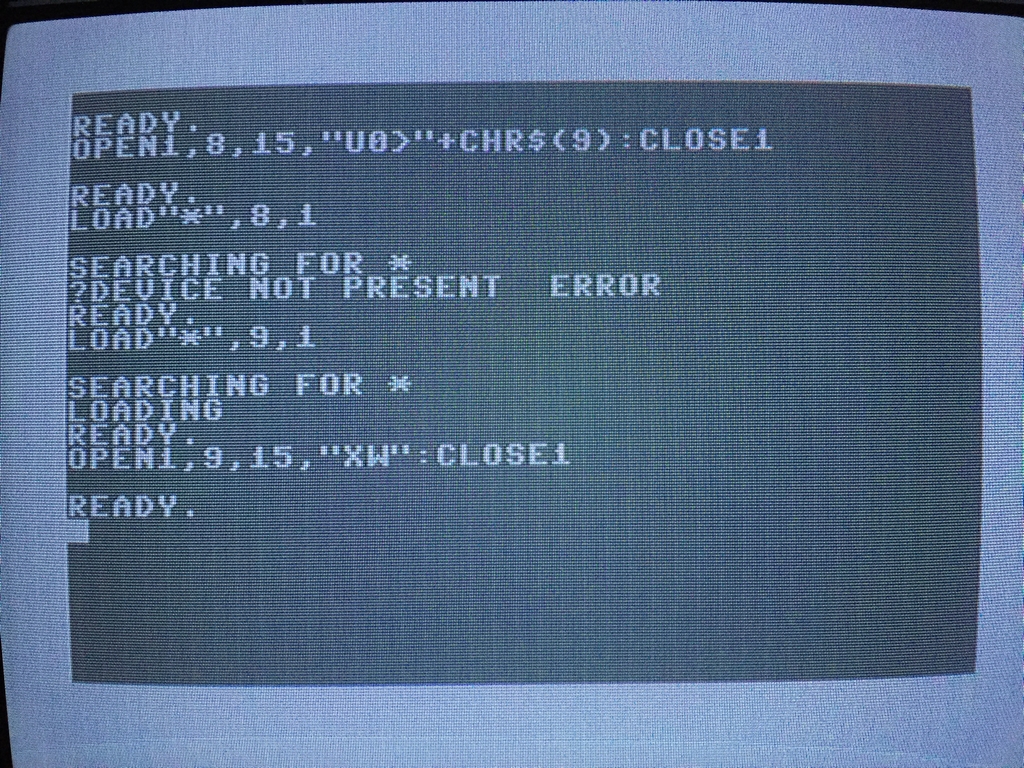
It’s not strictly neccessary to use the program for changing the device number as this can easily be achieved using BASIC commands, but the program sure makes it easy to do! The following two BASIC commands will change the SD2IEC device ID from 8 to 9 and then save it as the default device number: OPEN1,8,15,”U0>”+CHR$(9):CLOSE1 and OPEN1,9,15,”XW”:CLOSE1. It looks like this on the Commodore 64 screen.
The device also has soldering pads for changing device ID’s by the push of a button. I did not apply cables and buttons to use this feature as I wanted to keep the installation as simple as possible (and very rarely changes the device ID).
Final Thoughts:
16×8 Digital Retrovation has several Commodore 64 devices in their shop including the Super VIDEO Board (reviewed here, link) and the more advanced SD2IEC EVO2 which has display support. Focusing on the SD2IEC Mini, the device is cheaper than the average SD2IEC solution on the retro market, primarily because is comes without a case (which would hamper the internal installation…), cables and pin headers. In use, it works just like any other SD2IEC device I have tried so far. The big question is, do I like the SD2IEC Mini from 16×8 Digital Retrovation? Well, it’s small, it’s blue, it works right out of the box, the device ID can easily be changed using the free config tool and it has some nice big mounting holes for easy attachment to the internals of a Commodore 64 case – so what’s not to like? If looking for an internal SD2IEC device, this little blue gem is definately worth checking out. Well done 16xEight!
© breadbox64.com 2016
Hi, I just purchased one of these. I have a 250407 rev.A motherboard. Do you think the lines for the serial port would be found in the same place as in your diagram? Is there a way to find out? Thanks, Linden
Hi Linden, yes they are the same 🙂 You can use this image from an Assy 250425 long board for comparison (link). May I ask where you got the SD2IEC Mini from? I thought the 16×8 Digital Retrovation store was closed…
Thanks for the reply. I just got it off e-bay. I did buy it back in October last year though.
UPDATE: some of the 16xeight products are available at Heimes-elektronik.de (link) in Germany 🙂
I bought one of these from Heimes-elektronik.de, and while waiting (forever) for it to arrive I decided to make my own (just breadboarding, no fancy PCB with cassette port and IEC connections external), quite a lesson/learning. Finally when this arrived, I decided to drop it inside my 64C, instead of externally. I cut a SD card slot in the case, a hole for a reset button, and used the grill space to flush mount some LEDs. Next/Previous I chose not to add a switch (maybe later). The LEDs were rectangular and with some coaxing slid right in the grill. Because of the LEDs I used, I added to the on board SMD 470 resistors; bringing resistance to about 1k and the brightness down. The COM is common to both LED and is often mistaken for GND – it is +5vdc.
Because, I wanted the SD slot, Reset, and LEDs exposed, I spent more time on figuring out the best place to locate them. Inside, I made it easy to replace if needed by soldering pins to pads supporting Dupont connectors. Also added pins to the 6-pin ATMega interface point to support hard flashing, and for the added Reset switch. The reset switch used Pins 1,2,3 (GND, VCC and RESET). One side of the switch to GND, the other side of the switch had one wire to RESET, and another wire with 100 ohm resister to VCC.
This was my approach to use this, and Thanks to MtnBuffalo for the inspiration.