
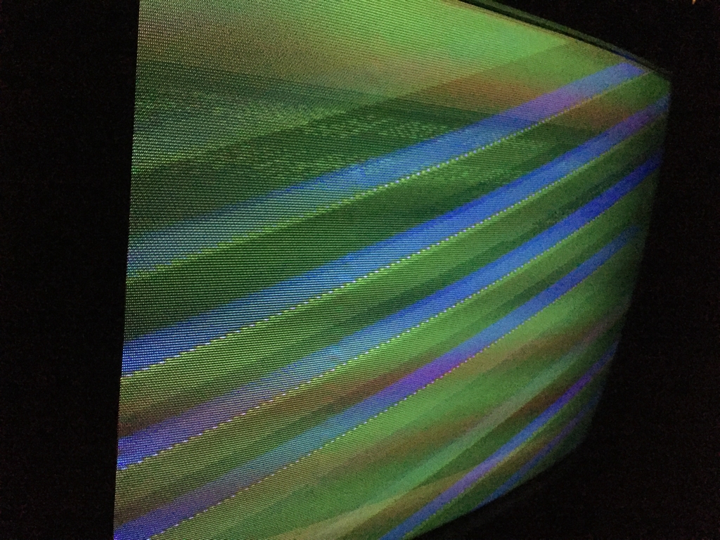
The video signals coming from the Commodore 64 may be challenged by numerous factors including the version of VIC-II graphics chip being used and the applied display technology (e.g. LCD, LED, Plasma or CRT). The problems are easily recognized in the form of vertical lines (banding artifacts) or as a checkered pattern spanning across most of the screen, depending on the monitor signal being used (Composite or S-video). An easy improvement strategy is the addition of the LumaFix64 device as described here (link). In this context, a more radical approach is the removal/replacement of the entire Commodore 64 RF modulator box to refine the quality of the S-video signal (which is generally viewed as the best video output). As the RF box holds the circuitry necessary for S-video output (luminance and chrominance), it cannot be removed without some kind of replacement circuit. Furthermore, removal of the RF box may improve the S-video signal but will remove the aerial connection as well as the composite video signal. In my opinion, that is a sacrifice I can live with as long as it improves the S-video quality.
The Super VIDEO Board:
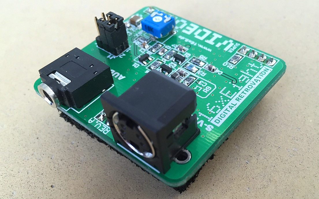
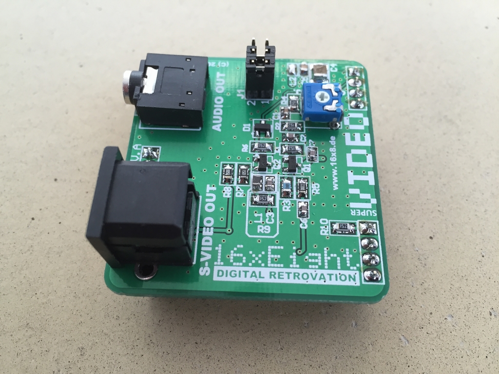
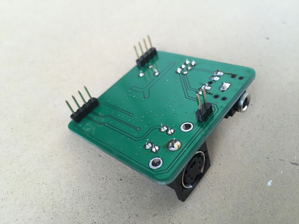
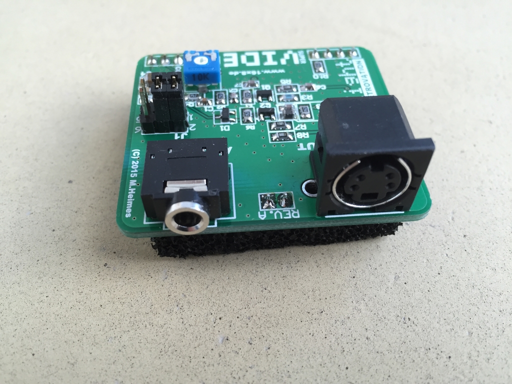
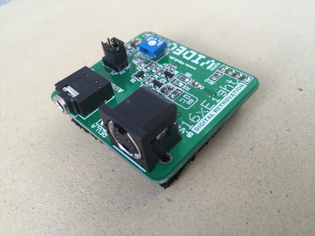
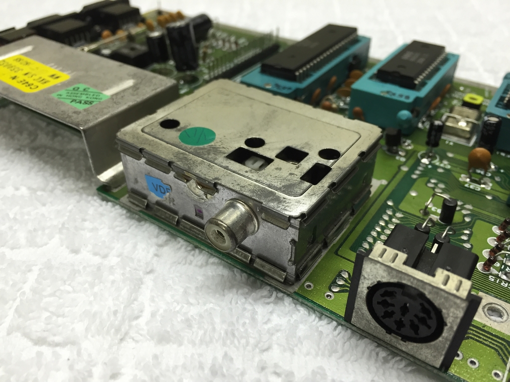
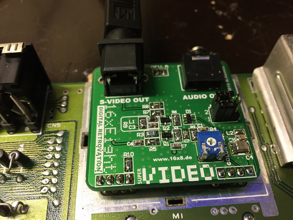
As described above, the mod requires a substitute circuit for the RF box and 16×8 Digital Retrovation (link) has made a neat solution that is ‘plug-n-solder’. Their device is called a Super VIDEO board and has a S-video output connector and a 3.5 mm mini jack output plug for the sound. It only fits the Commodore 64 Version E short boards (Assy 250469, link), but should also fit the Commodore 128’s. The device costs 21$ without shipping from Germany and it looks like this:
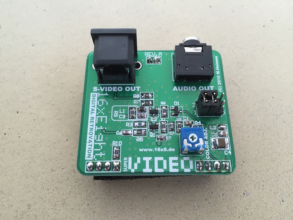
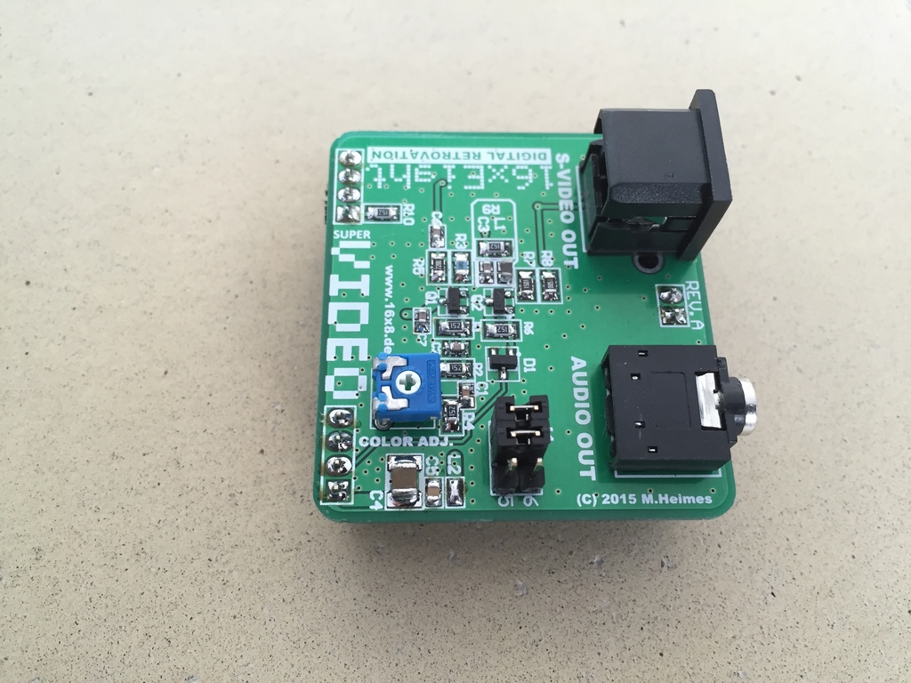
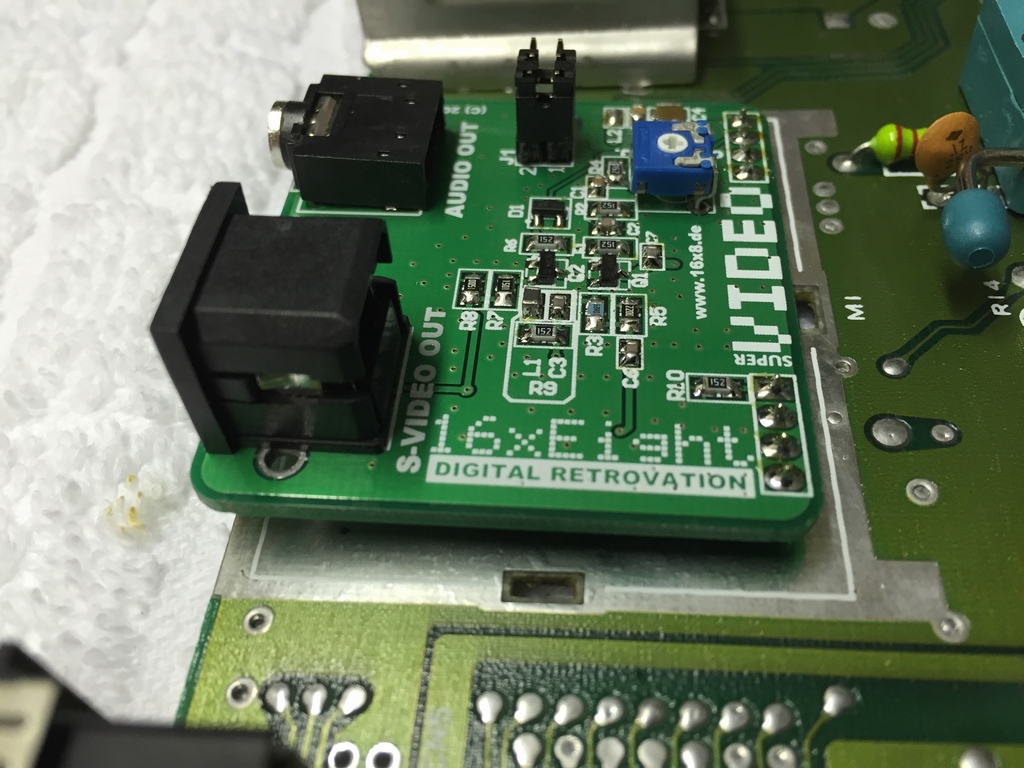
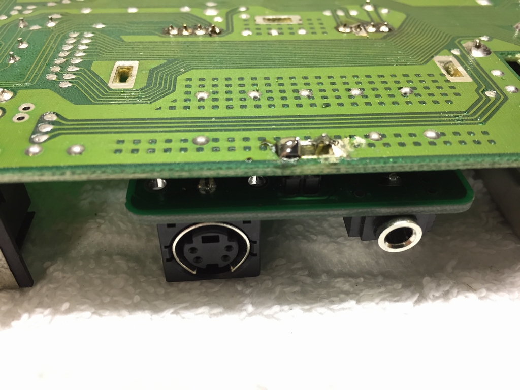
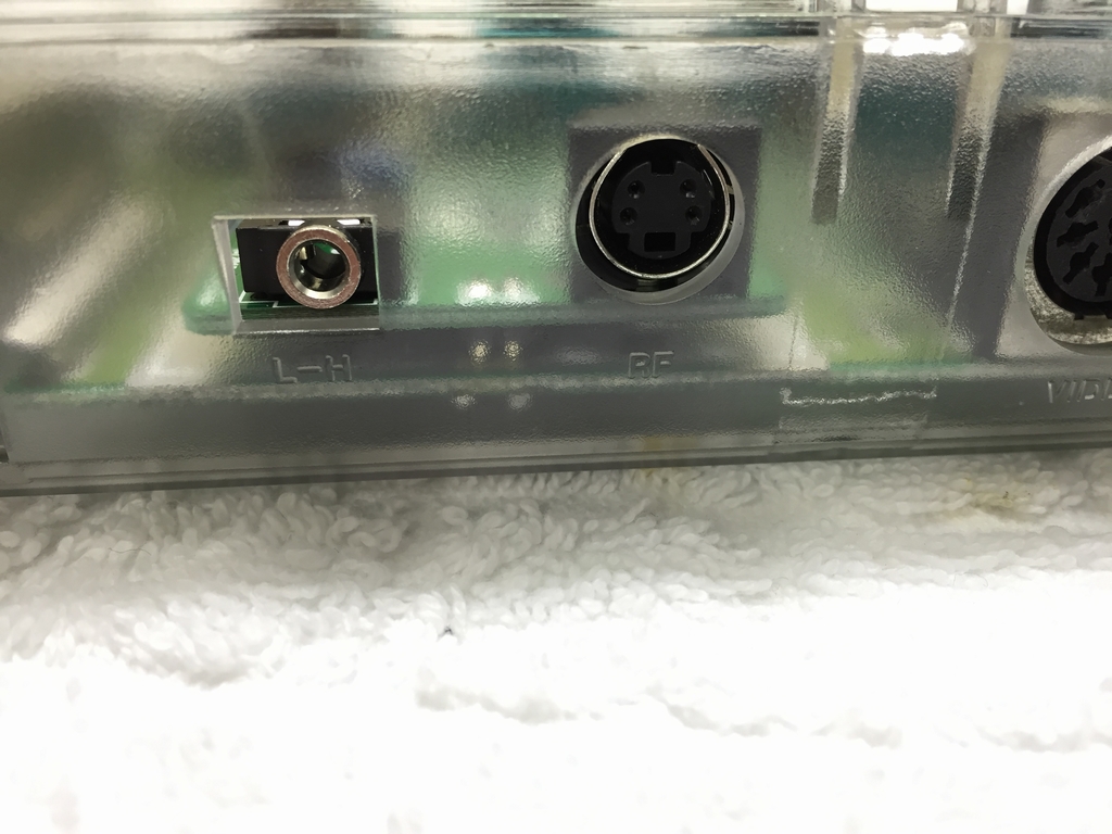
The two pins in the front are ground and can be used to adjust the mouting height of the Super VIDEO board. The S-video and 3.5 mm mini jack sound connectors can easily be reached using the holes in the Commodore 64C cases. No need for drilling new holes!
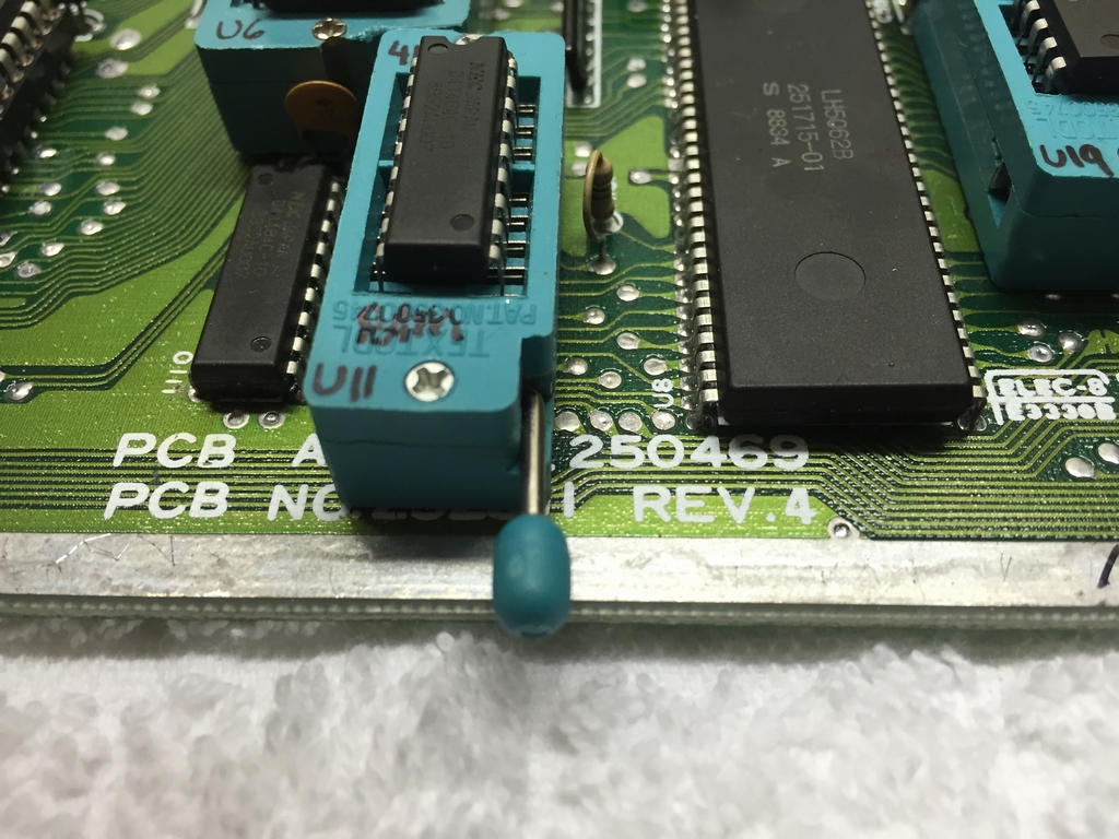
The mod was applied to my ZIF socket modded Assy 250469 Rev. 4 short board motherboard (link)
Installation:
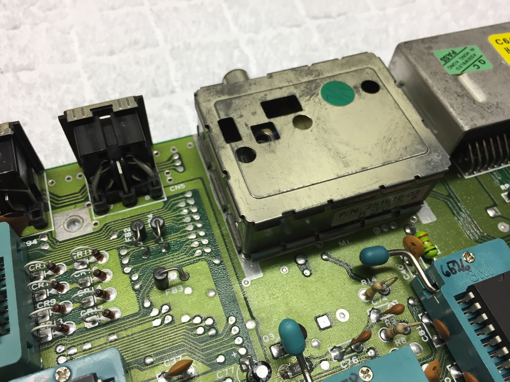
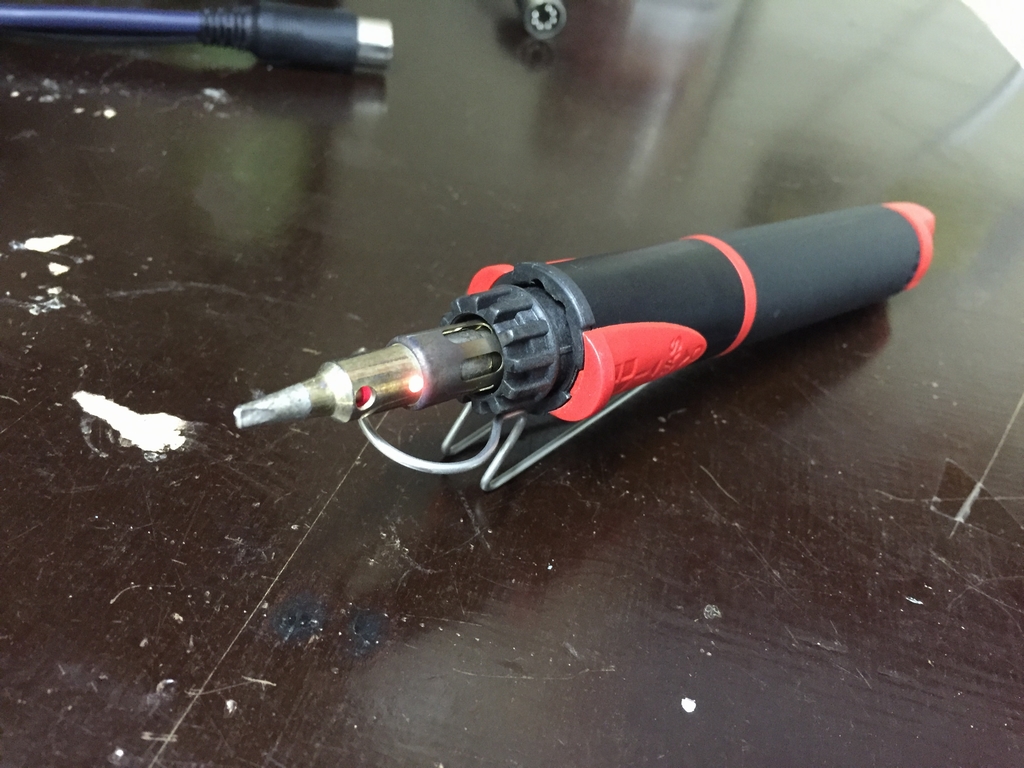
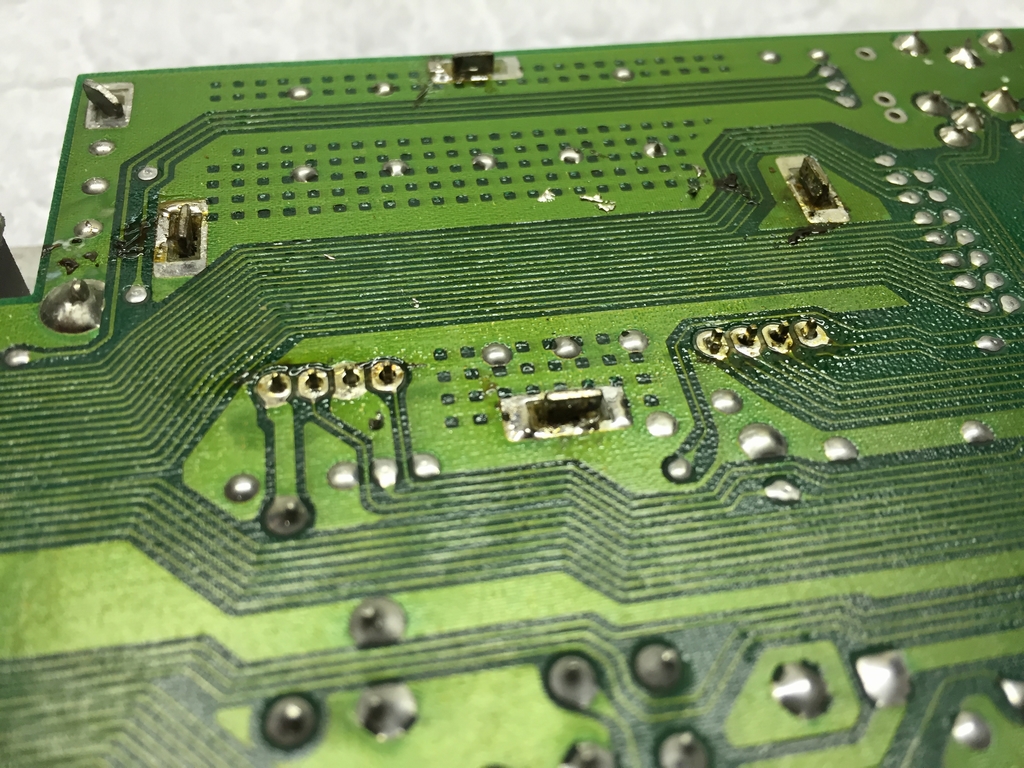
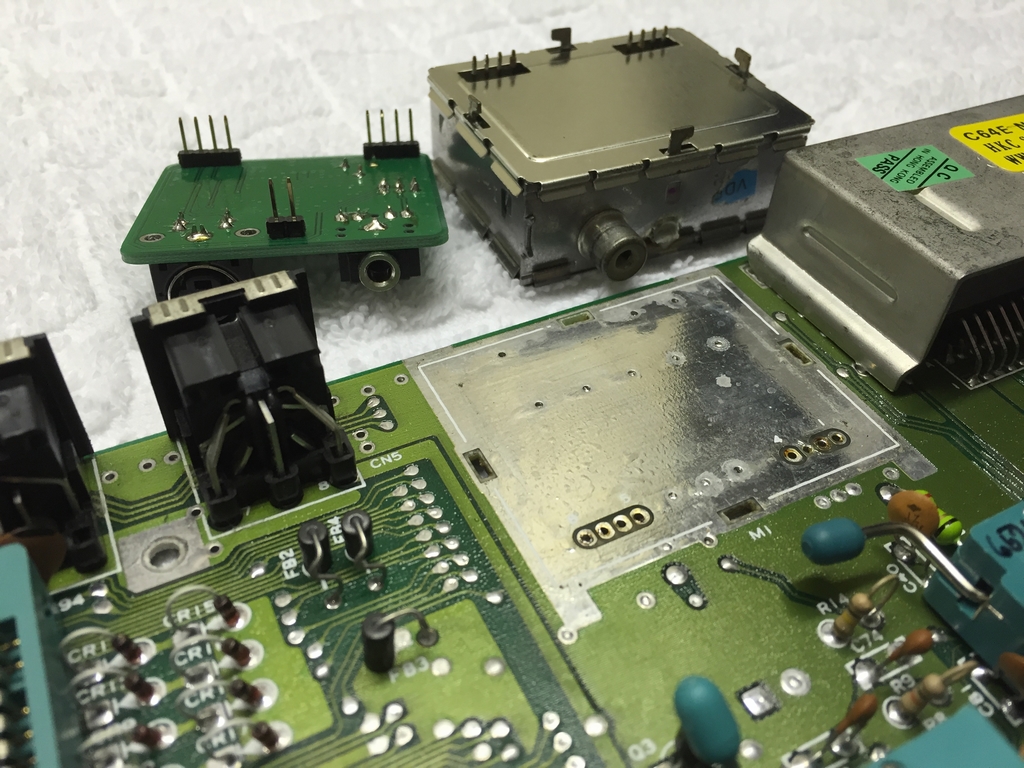
The stock Commodore 64C RF modulator box was removed using my gas soldering iron as this device can dissipate tons of heat and makes de-soldering easy. I also used a heat-gun to make the process as easy as possible. A total of eight pins had to be de-soldered to remove the original RF box.
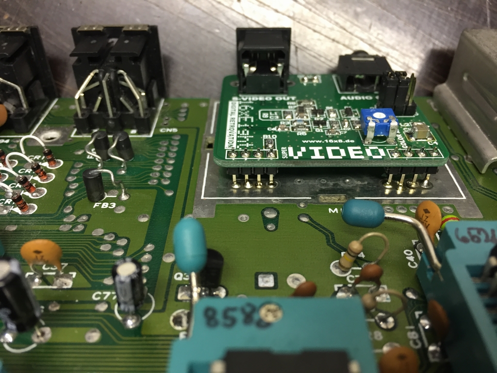
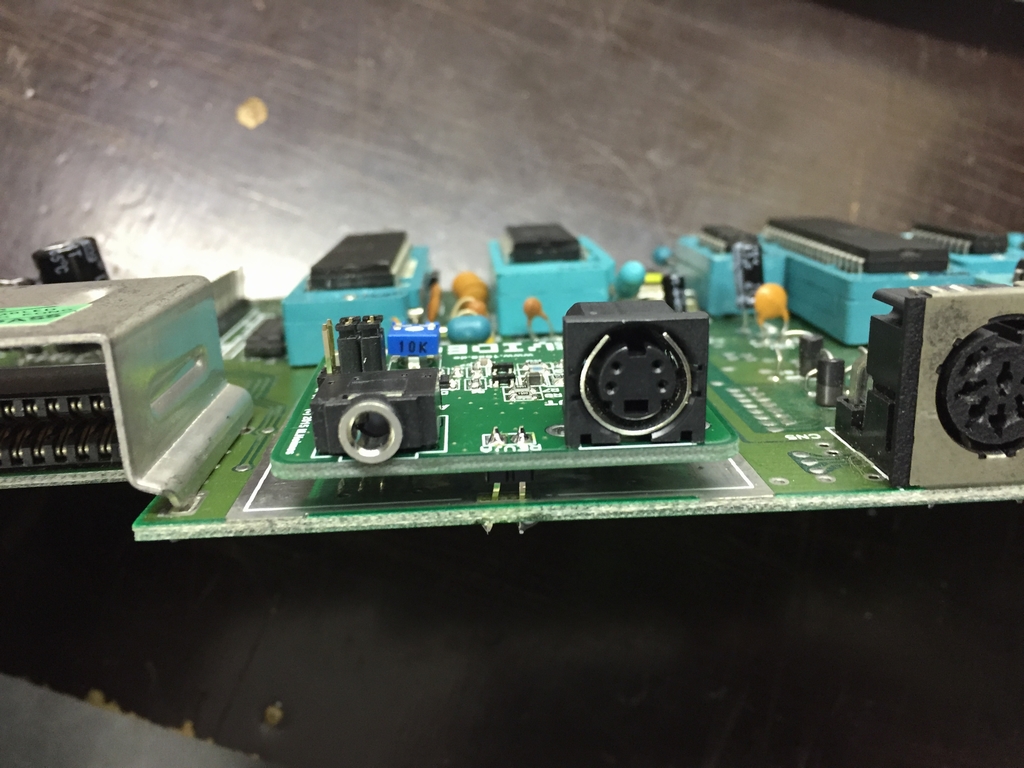
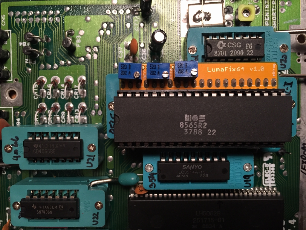
The RF replacement circuit installed and ready to be tested. The blue potentiometer can be used to tweak the intensity of the colors. Before soldering the front two pins, the level af the board was double checked to make sure that the plugs could reached through the case openings.
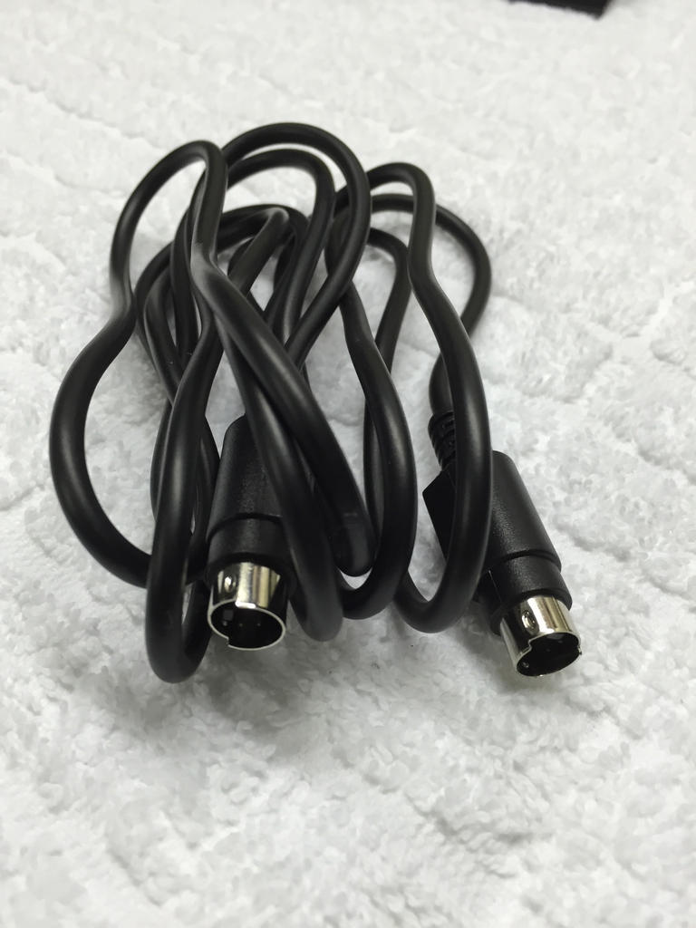
A S-video cable was found in the drawer…
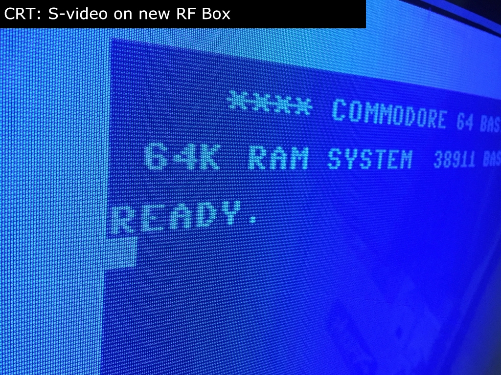
…and the image on my CRT and Plasma TV’s looked like this…
Rrrrggghhhh…total disappointment!!!! I then removed the Super VIDEO board and re-soldered the original RF modulator box. The machine was working again, meaning that the device I purchased was faulty! After a single e-mail to 16×8 Digital Retrovation, they sent me a replacement PCB and this time it worked!
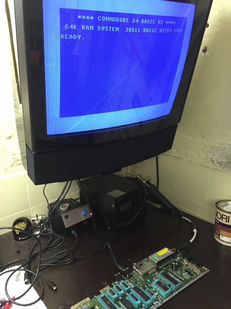
Image Examples:
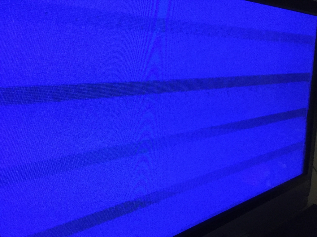
Here are some pictures using the S-video output on my B&O (Bang & Olufsen) BeoVision MX4000 21″ CRT television before and after the mod. The first image is the standard S-video output before the RF box mod and the second image is the S-video output from the new RF box (after the mod). It should be evident that the vertical stripes are less pronounced after replacement of the RF box.
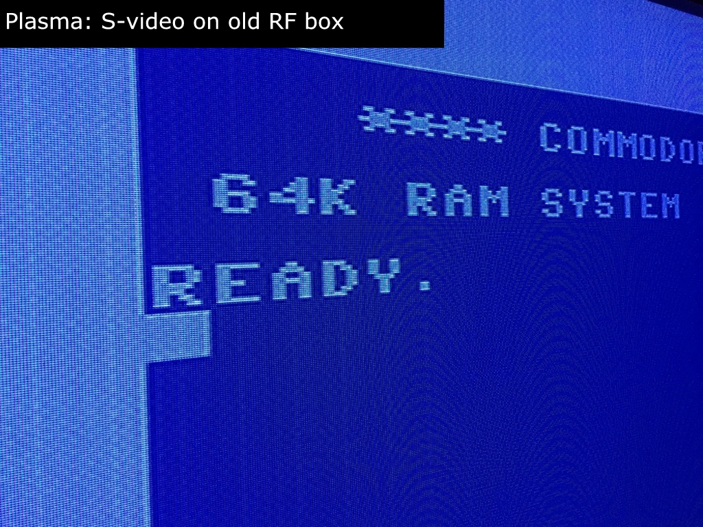
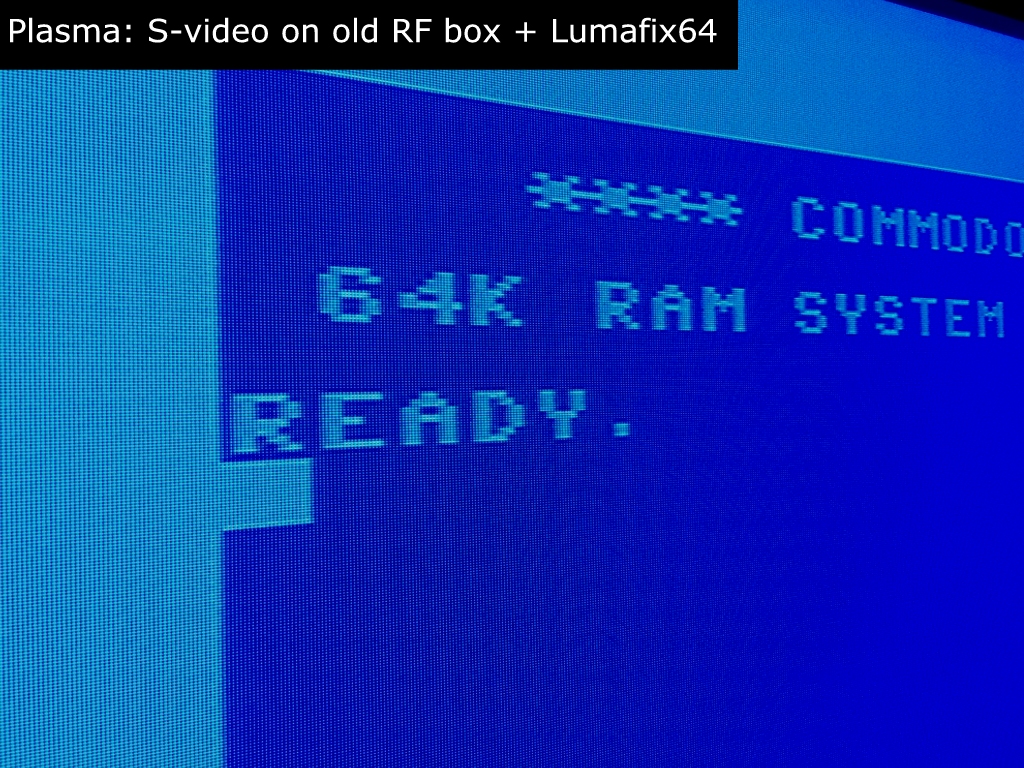
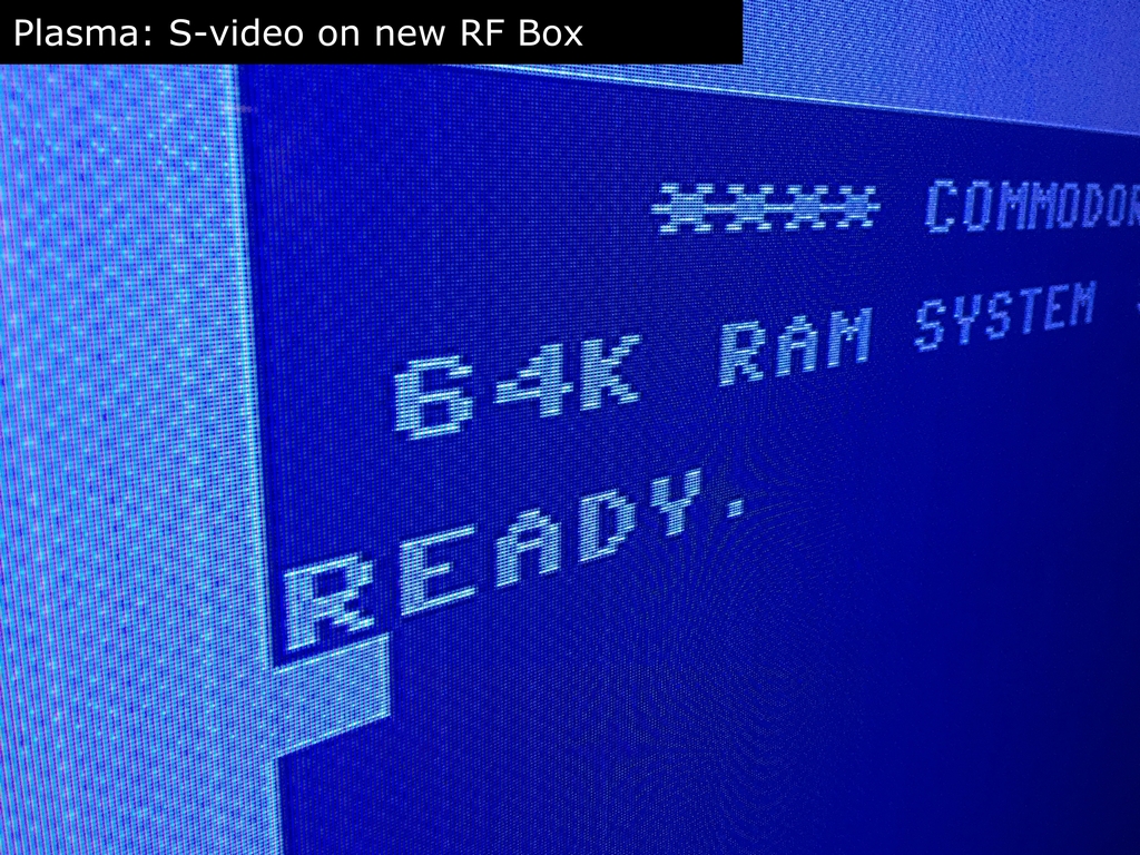
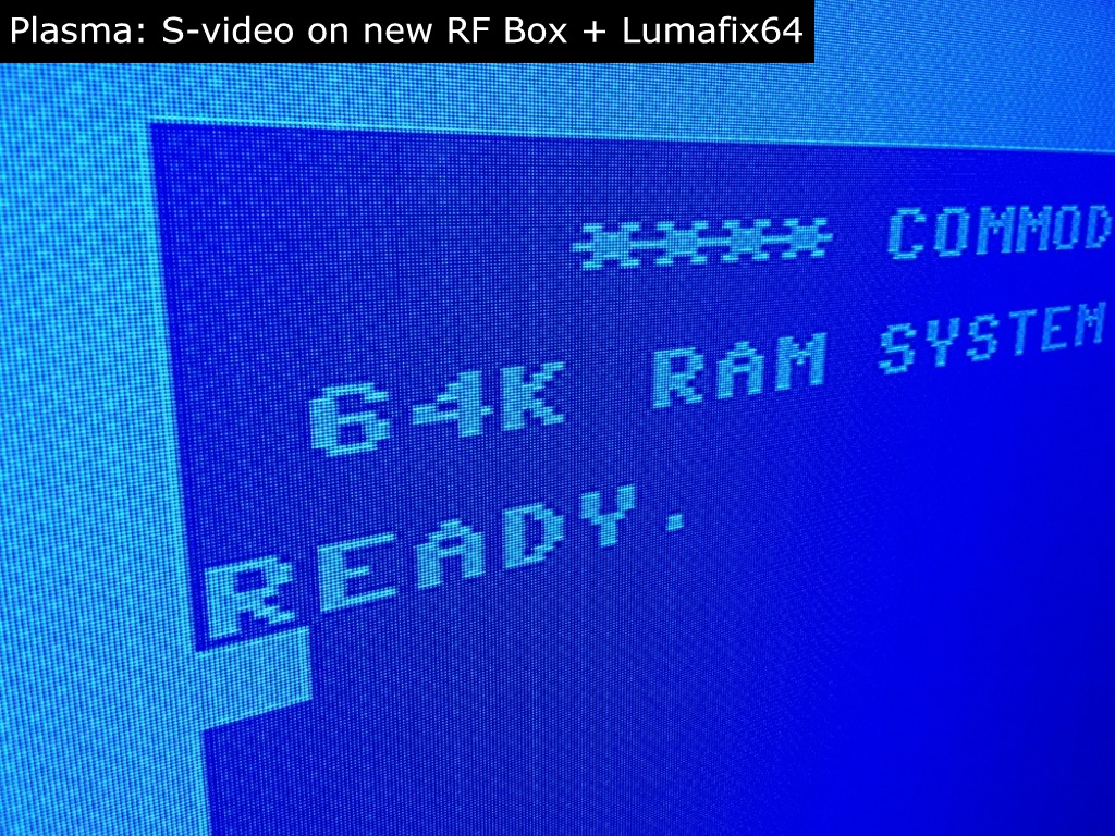
Before the mod I also shot some pictures of the image quality on my 42 inch plasma TV in the living room. As I knew that the S-video related artifacts would be very pronounced on this TV set I also tested it with the LumaFix64. The results, especially when using the LumaFix64, were acceptable as should be evident from these images taken before the RF box mod:
After replacement of the RF modulator box, the images were quite affected by vertical stripes and checkered patterns. I found that the images from the Super VIDEO board were worse in direct comparison to the images from before the mod. Adding the Lumafix64 improved things a little, but kinda goes against the whole idea of just doing the RF box mod for improving the S-video image quality. As evident from these pictures, the Lumafix64 cleared up the image a little but I was not able to remove the artifacts completely.
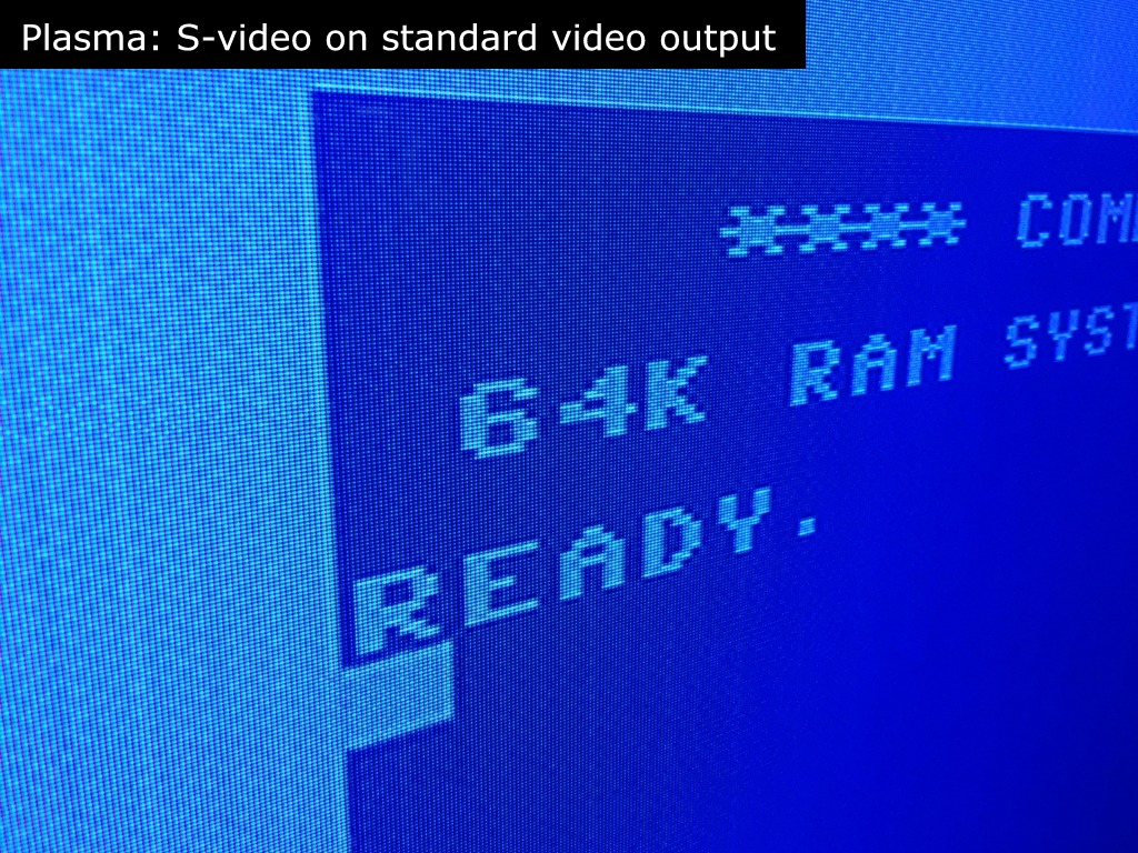
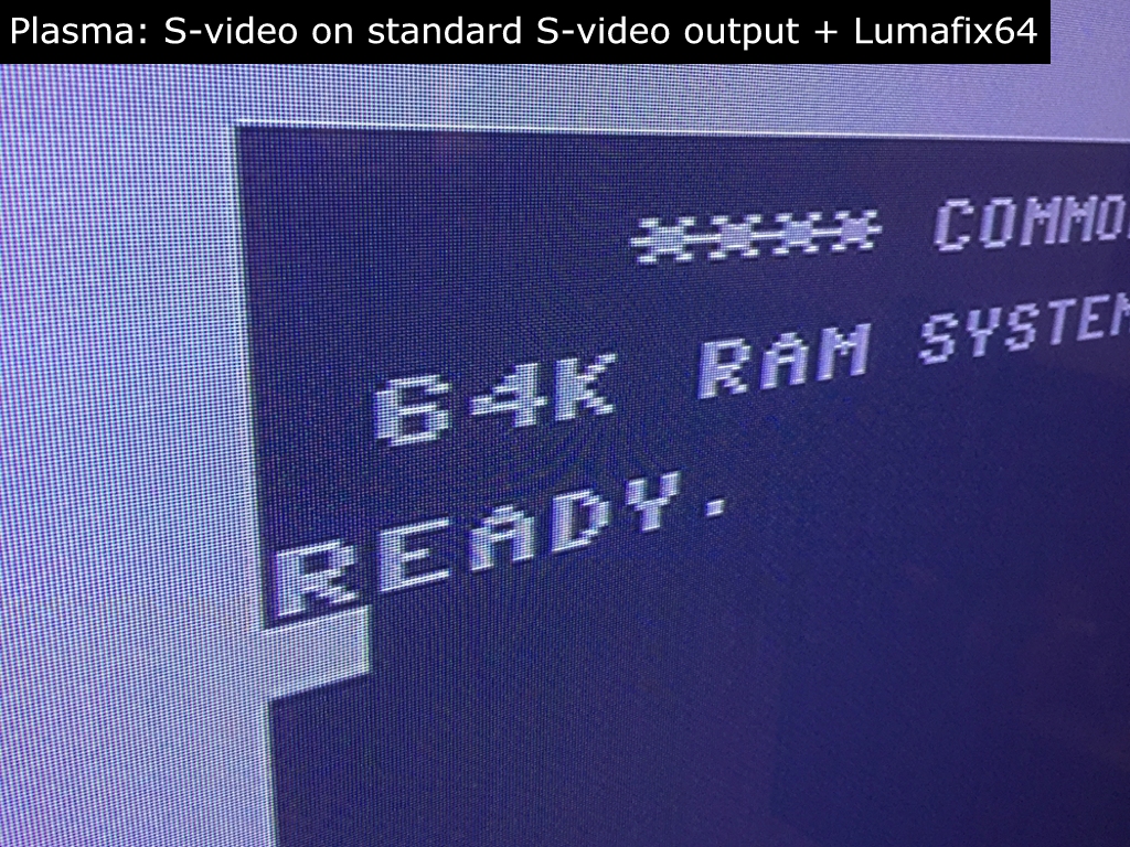
Just for the fun of it, I also tested the S-video signal from the original 8 pin DIN connector with and without the Lumafix64 on the plasma screen (while the Super VIDEO board was still installed). Using this output yielded a better picture than the signal from the new RF box! Adding the Lumafix64 improved the image even further and superseded the image obtained from the RF box. However, the colors changed to a darker/greyish color which I was not able to remove even with the LumaFix64 installed.
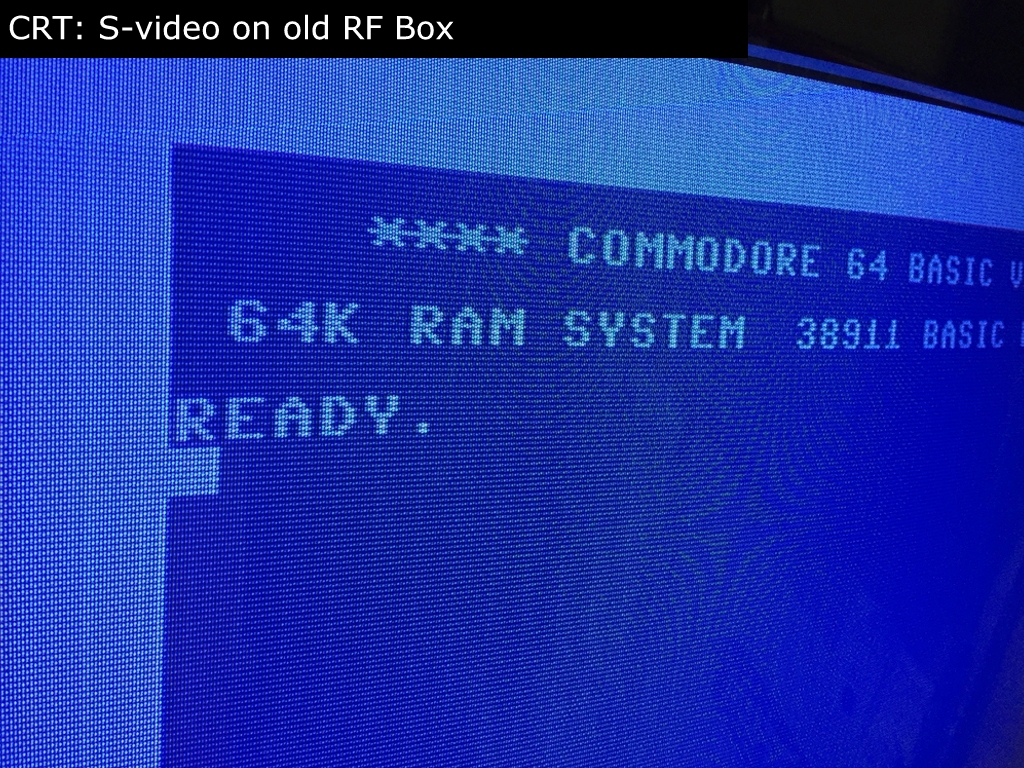
The manual of the device states that the composite video signal should still be available even after the modification. However, this is how the composite signal looked like after the mod on my CRT TV. The blue start-up screen text is barely visible, but I would say its useless 🙁 No biggie as I never use the composite signal anyways!
Final Thoughts:
Is the RF box mod worth the hassle of soldering? The short answer is yes to CRTs and no to flatscreens… If you primarily use a quality CRT television like me, always use the S-video signal and feel comfortable with a soldering iron, the C64C RF box mod will improve the image quality slightly. That being said, I find the improvement in image quality to be so small that I will only apply it in my primary machine. I will therefore not start replacing RF boxes in all of my machines. The 3.5mm mini jack provides an easy way to transfer the sound to a lager sound system and the sound quality should be better in comparison to the sound coming from the stock 8 pin DIN video connector. As the sound produced by my B&O CRT TV is really great, this option is not a turning point for me.
If your primary display is of a more modern breed (e.g. LED, LCD, Plasma) you will most likely experience a greater improvement in image quality with a LumaFix64 than with the Super VIDEO board from 16×8 Digital Retrovation. Using the LumaFix64 will also save you some soldering… Based on my tests, the device did not improve the image quality on my plasma TV. Other TV technologies (e.g. LED) may behave differently to the RF box mod, I just have no way of testing this. It should also be mentioned that this mod was carried out on a Commodore 64 short board (which the device was created for). More positive results are to be expected (according to several online C64 forums) using older motherboards with older revision VIC-II chips. However, this requires a different hardware solution. The device may also perform better in the Commodore 128’s, but again, I have no way of testing it in that hardware either.
As stated above, the mod was carried out using a short board motherboard (Assy 250469). The VIC-II chips in these machines (MOS 8565) are, in my experience, notorious for their poor image quality. Thus, if image quality is a top priority, try to get a Commodore 64 with a long board and a MOS 6569R5 VIC-II graphic’s chip. This specific chip holds the best obtainable image quality on any Commodore 64 I have seen.
© breadbox64.com 2016
Thanks! Super handy evaluation of the options. I’ve just ordered the RF replacement but thinking I should’ve got a Lumafix instead. Thanks for the write up.
Thanks Rowan. Glad you liked the review 🙂 Please let me know if you experience different results with the Super VIDEO board than I did.
Thanks for this – nice write up. I was looking at purchasing this as well. Currently I have a cable I bought off of ebay which supplies both a composite and s-video signal to a SCART connection. There is a switch built into the cable that will either output the composite signal or the s-video to the SCART. I then have the SCART plugged into a SCART>HDMI converter, then out to my flatscreen Samsung T260HD tv/monitor. I’m also using a LumaFix64 v1.01. The image quality is very good when the switch is set to composite signal on the cable, when I switch it over to s-video, I get an image similar to what you describe above in your “Plasma: S-video on standard s-video output with Lumafix64” screenshot. The cable has a 300ohm resistor in it, so I was wondering if the doublefiltering between the cable and the LumaFix was giving me the washed out/dull colors on s-video output. So I removed the Lumafix, but the result was the same. I was thinking about purchasing Super Video Board to tinker with and have fun – and maybe see if it improved the signal out of the standard commodore video output (the one that I have the scart cable plugged in) but now I’m concerned it will destroy my composite output and then I will still have the washed out colors from the s-video output. I’m very curious as to what is causing the dull/washed out color – it’s not black and white. makes me think there is a different problem on the C64c motherboard going on – or something with the old RF modulator that is throwing things off…
Great article, thanks again…I am partially thinking out loud and also sharing experiences to bounce ideas off of others.
Hi Tom Mc. Thanks for sharing your thoughts. It sounds like there may be an issue with your cable as the dull colors are present even without the LumaFix64 installed. Changing the RF modulator is probably not going to fix this 🙁 The visual image quality of the S-video signal (using the standard/old 8-pin A/V port), based on my tests, is pretty much the same independent of which RF modulator is being used. However, exchanging the RF box may therefore just lead to a loss of your composite signal 🙁
Hope you find a solution and please share your findings with the project!
Hi, does this s-video work on a C64C Assy 250469, PCB 252311 REV.A? Thank you!
Yes, it should work on all short boards regardless of revision 🙂
Where do you get the RF Mod Kit?
I get it from 16×8 Digital Retrovation (link) but I see that their site is currently down… They also have a store on Ebay – their user is called ‘dellidaniel’. You may be able toi get a hold of them from there 🙂
Can already get all that out of the U shape din plug. On mine I even used pin 7 for the 2nd SID chip sound.
It would be good if someone made some video overlay to fit inside the RF-box. Or output a HDMI from it.
Hi, I know that it isn’t designed for a breadbin board (250407 Rev A), but would it work? I would like to have room for other connectors without making holes in the case.
I don’t think is will work on a long board. However, if you choose to go ahead and do it anyways, please share the results 🙂
“I get it from 16×8 Digital Retrovation (link) but I see that their site is currently down… They also have a store on Ebay – their user is called ‘dellidaniel’. You may be able toi get a hold of them from there ?”
Site still down and Ebay account no longer exists.
Has anyone tried this SuperVIDEO board on long boards, like 250425? Is it generally not compatible at all, or is this just more that the RF modulator size is different and it is just a matter of “plug-and-solder”?
Looking at the board, it seems to be just a PCB layout of this board (link) which is a stripped down version of the original RF modulator schematics from the service manual without the actual rf-modulation part. This will probably not improve anything. You will also get the S-Video from the regular video interface, with or without this. With this, you get it a few solder traces earlier and using a S-Video cable + 3.5mm audio jack (S-video carries no audio). I would consider this as a replacement for a broken RF modulator when you don’t actually need the actual RF modulation. It does add the 10K “color adjust” pot, I don’t know which resistor in the schematic it replaces.
Btw, looking at the pictures, it seems to be hand soldered and L2 seems to have been replaced with a blob of solder, which would explain the lack of composite.
Anyone knows if lumafix is apliable to 6572 VIC2? (PAL N)
Hi there, I honestly don’t know – sorry ? If I was you, I would contact e5frog from lemon64.com and ask him as he has designed the LumaFix64. Tim Harris from Shareware Plus has produced the version I have and he may also know wheter or not the LumaFix64 works on Drean C64’s. Please report back if you find the answer as other South American users may be interested in the LumaFix64. Thanks ?
Review much appreciated, however read this after I ordered the SuperVideo board. Regardless, as an exercise I will be going through this on one of my C64C short boards and evaluate my experience. I’ll make sure to post any other findings if relevant.
If interested, the SuperVideo can be found at “https://heimes-elektronik.de/index.php/rega” It is about ~$20EU, and if ordering from US, expect a ~6-8week delivery time.
Summary evaluation of SuperVideo Rev B (updated version of the device)
The updated SuperVideo board does help to clear up some video issues but is a trade off with others. Added S-Video connector and audio din are handy add-ons. As a learning exercise to understand video issues and causes well worth the endeavor. However, as an out of the box solution, recommended to look at other solutions based on needs and/or problems; perhaps LumaFix64.
Installation:
Installation instructions are definitely thin; however for those familiar with replacing components on the C64, they are reasonable. Where instructions are needed more are with non-apparent items and the features and function of the board components. It makes it very difficult when the product advertises you can adjust the AEC or the Color saturation but tells you nothing in instructions on how to do this, or which of the two potentiometers control what function. Fortunately, tucked between the pots and jumpers there is silkscreened “AEC and “COL”. I missed this the first time and also overlooked the “AEC IN” pad near the front edge.
Additionally, product promoted pictures I could find illustrate a 501 (500ohm) and a 102 (1kohm) trimmers, however the board I received had installed two 102 trimmers; perhaps a later alteration for greater resistance needed, or someone ran out of 501 trimmers, or 102 looks like 501 upside-down?
These trimmer (trim pot) models are a bit tricky as there is no hard stop. Their adjustment range is about 20-25 full turns from end to end. Inside they have a “wiper idle” mechanism, which allows them to continue to be turned while the resistance value remains the same; e.g. for a 102 trim pot this is either 0ohms or 1kohm depending if the low or high end is reached. The AEC control is the Left trim pot and the Color Saturation is on the right; when looking front to the back of the C64
Also on the board there are 3 jumper sets number 1-2, 3-4, and 5-6. Nothing is said about these in the instructions. However if you look at the traces on the back of the board it shows that jumper positions 1-2 and 3-4 allow the Audio out to go to both the Left and Right channels of the 3.5mm audio jack; for supporting dual SID integrations. Position 5-6, does not look like it is connected, but I did no research this further.
Testing
Understand the below is critical and under specific conditions, however key experiences do parallel with the MtnBuffalo review.
For testing, I used my C64C 250469 RevA NTSC, a Sony 4k LED panel and Proscan 1080 LED panel; both panels with same results and the following connection methods used. I did not have any monitor that accepted S-Video directly and the S-Video to Composite connection would not work. As a result, I also introduced a converter box.
Configurations: C64C to LED panel TV/Monitor
1. DIN to Composite out Working Mixed results
2. DIN to Composite to HDMI out Working Pronounce issues – Converter box used
3. S-Video to Composite out Not working Cause not isolated
4. S-Video to HDMI out Working Pronounce issues – Converter box used
5. S-Video to Composite to HDMI out Working Pronounce issues – Converter box used
For visual testing, I used a diagnostic card or software with a color pattern, intro/demo from Dino Eggs, and a few other game tests. My primary testing was done from C64C DIN to Composite out (Configuration 1); my normal means of use. Before adjusting, the screen only appeared marginally better with three noticeable changes; jail bars less distinct (softer), contrast lettering a bit crisper, however color tones muted.
Both C64C DIN and S-Video outputs both result in muted colors. Adjusting the Color Saturation was not found to be an improvement, however will reduce it to black and white image (if you want).
While some contrasting objects appear to be sharper, such as lettering and lines on a darker, or black background, other colors left “flickering” pixel artifacts that seemed to come and go as the color changed or objects on the screen moved. Some color patterns would also brighten/dim (or tone lighten/darken) periodically or as image changes. I believe this may be more a symptom of the checkerboard effect that is clearly visible now, and barely visible with my original RF board (252405-02). Using the S-Video connection issues were far greater pronounced; although S-Video was only tested through a converter box; S-video to HDMI or S-Video to Composite to HDMI.
Testing for configurations (2, 4, 5) resulted in slightly worse conditions; especially with checkerboard patterns, flickering, tonal fade, color bleeding. I place these issues (mostly) on the introduction of the HDMI converter box in the middle and the added signaling change circuitry.
Testing with a diagnostic color pattern made it clear that there was better results on contrasting colors, but worse results on similar color tomes.
Plugging in a stereo set of speakers to the board is a nice convenience and the (Mono) audio does work well out of both speakers. Without a dual SID solution installed, a true Stereo output was not evaluated; but no reason to suspect any issue.
Evaluation
Of the tests I performed, results were disappointing. If you need a replacement RF modulator, this is an option. If you are looking for improvements, don’t count on it. Instead this sits somewhere in between; not much better, and a little bit less satisfying; jail bars less distinct (softer), lettering a bit crisper, however colors muted; added S-Video connector and 3.5mm audio jack for single/dual SID.
I will give myself some time to reverse engineer, play with, and perhaps try to correct issues. However, if I don’t find any correction, the SuperVideo board will likely be removed and will be replaced by the original RF board.
I must acknowledge these are my findings and does not mean that there are other factors that play into results. Perhaps this is not a best NTSC solution, but works wonders on PAL? Conditions of the VIC II chip or other ICs on the motherboard play a factor? Perhaps more detailed use instructions from maker would help on adjustment settings and other points of awareness? Perhaps someone else has this working better without issue; either on a different board or with different IC set versions? Or….
Hi Jpenner64, thanks for the very thorough review of the updated version of the SuperVideo RF modulator replacement board! I’ve added an image to show the differences between the one I reviewed above and the one you tested 🙂 I’m doing a review on four other replacement RF modulator modules that I hope to publish soon! Stay tuned…