
…well almost… The machine still needs some new colored keycaps (hurry up Phase5!!!), a domed sticker at the bottom and a cold reset button using an Arduino Pro Mini. But I gotta have some modding goals for 2016, right? This machine has been build from a broken Assy 250425 Rev. A breadbox. The motherboard was the the first one I bought when I picked up the interest for the Commodore 64. It had a black screen which was easily fixed with a new replacement PLA (MOS 906114) at U17. The case was from another repair job that I ended up painting and decided to use it to host the PCB. The entire ‘Mod of the year 2015’ mod is a compilation of several previously described mods as well as a few new ones. I’ve worked on the machine for quite a while and eventually decided to finish it so I could do a little post about it. This is the complete list of what I have done on the breadbox so far:
Paint Mod
SD2IEC Mod
SIS2SID Stereo Mod
Potentiometer Mod
JiffyDOS & ROMs Mod
Capacitor & Voltage Regulators Mod
Heatsink Mod
PLA Mod
RESTORE Key Mod
Power LED Mod
Paint Mod
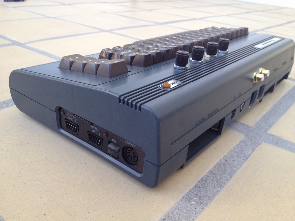
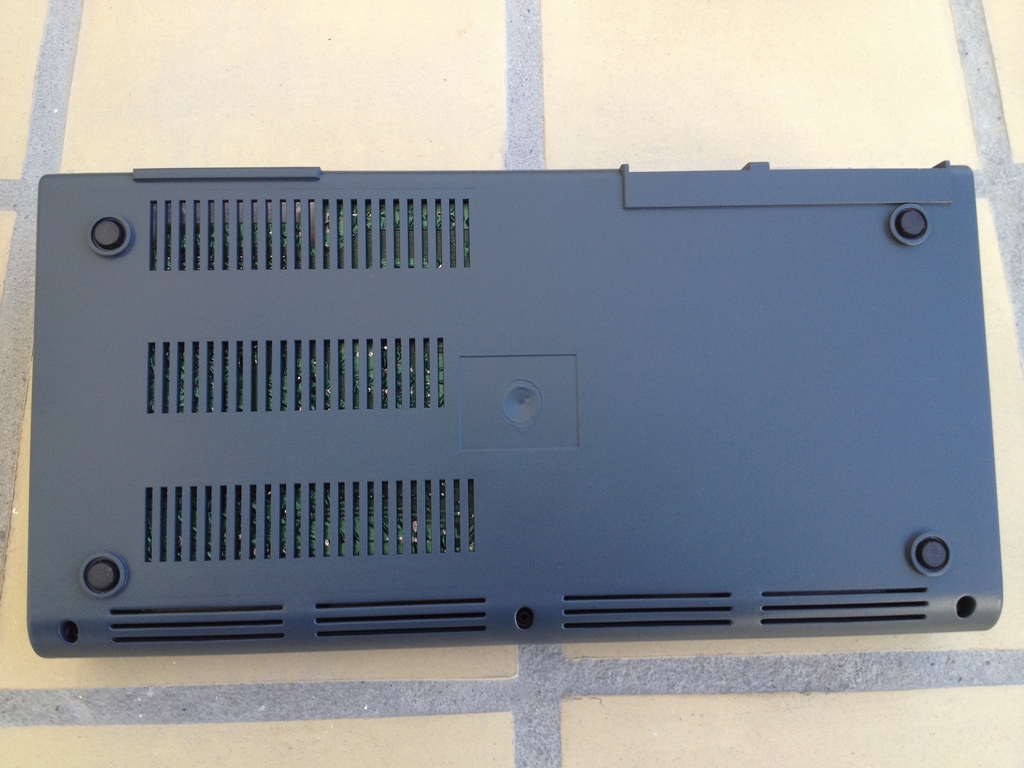
The breadbox case was really dirty when I got it, so I thought, ‘Hey, let’s see what 90 minutes at 60°C (140°F) in the dishwasher will do to it’. It was certainly clean when it came out, but the color of the case had faded and looked really bad. So I painted it with some Molotow spray paint in anthracite grey. In my own opinion, the result is not that bad! Now I just need some orange function keys and a stack of black keys to finish the looks of the keyboard.
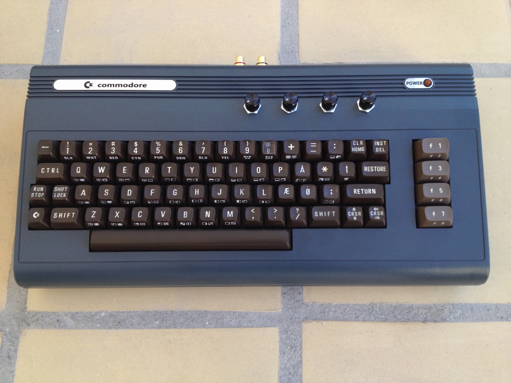
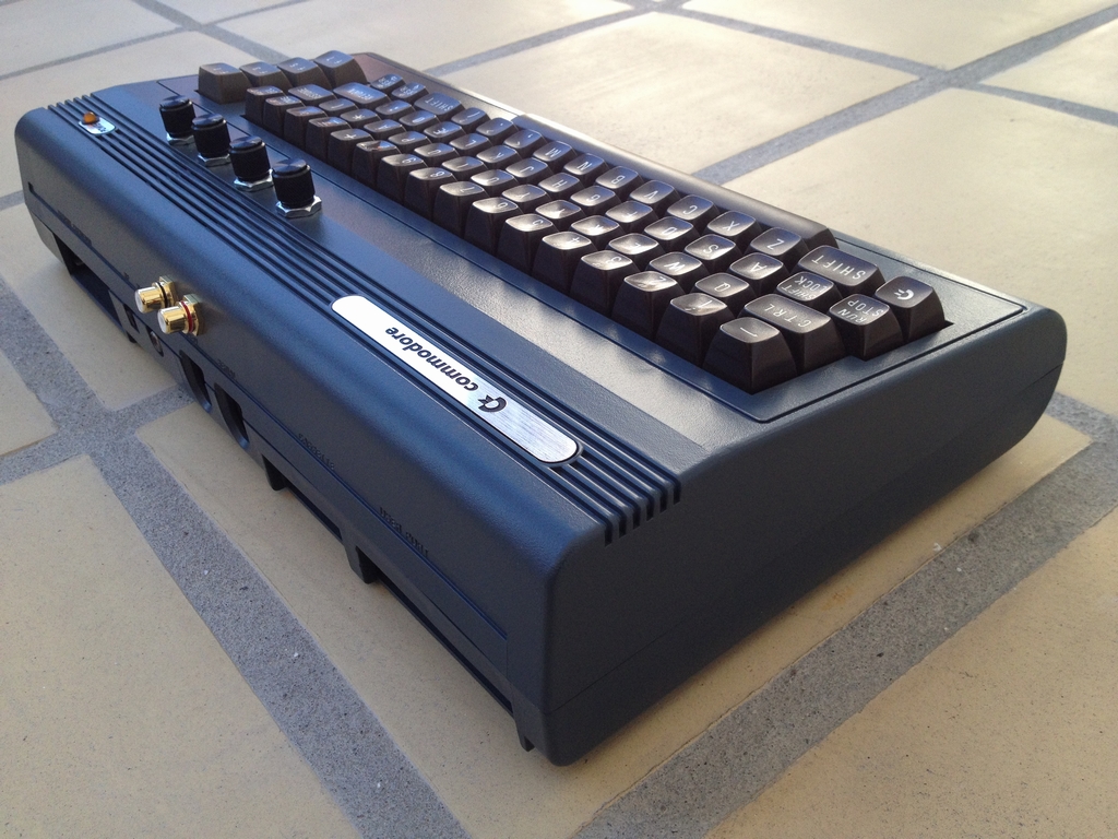
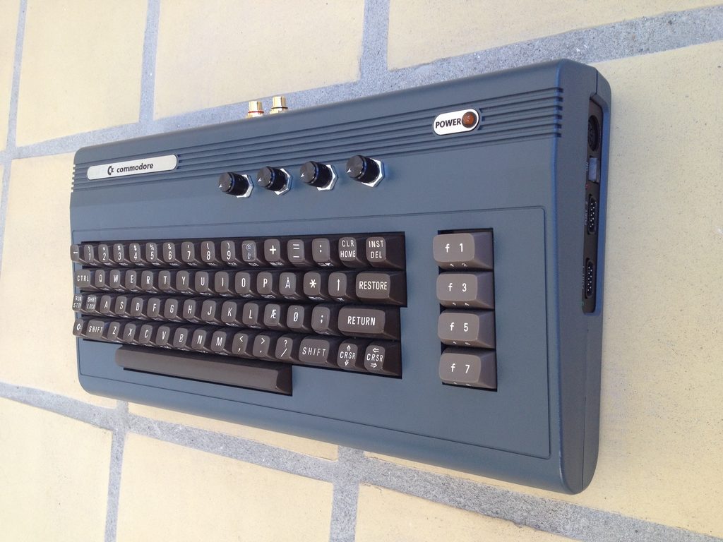
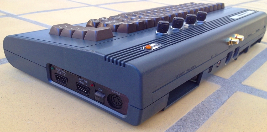
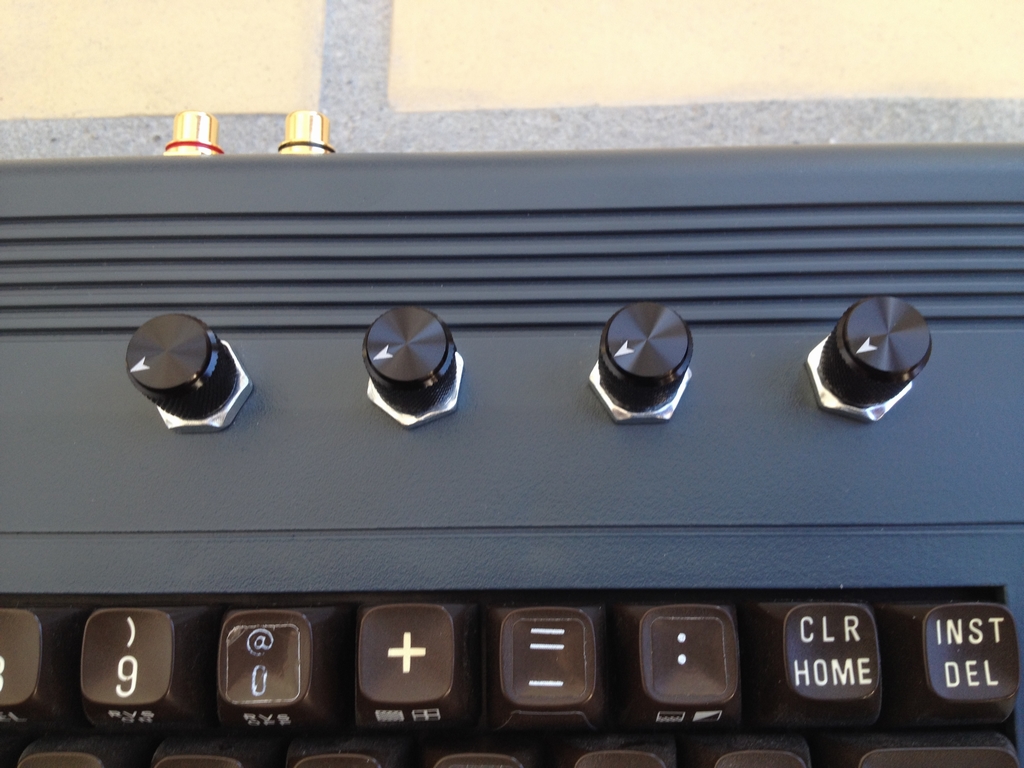
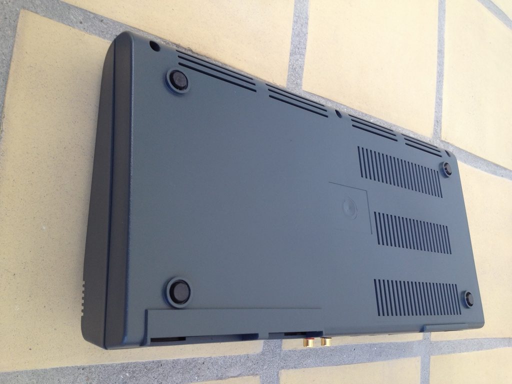
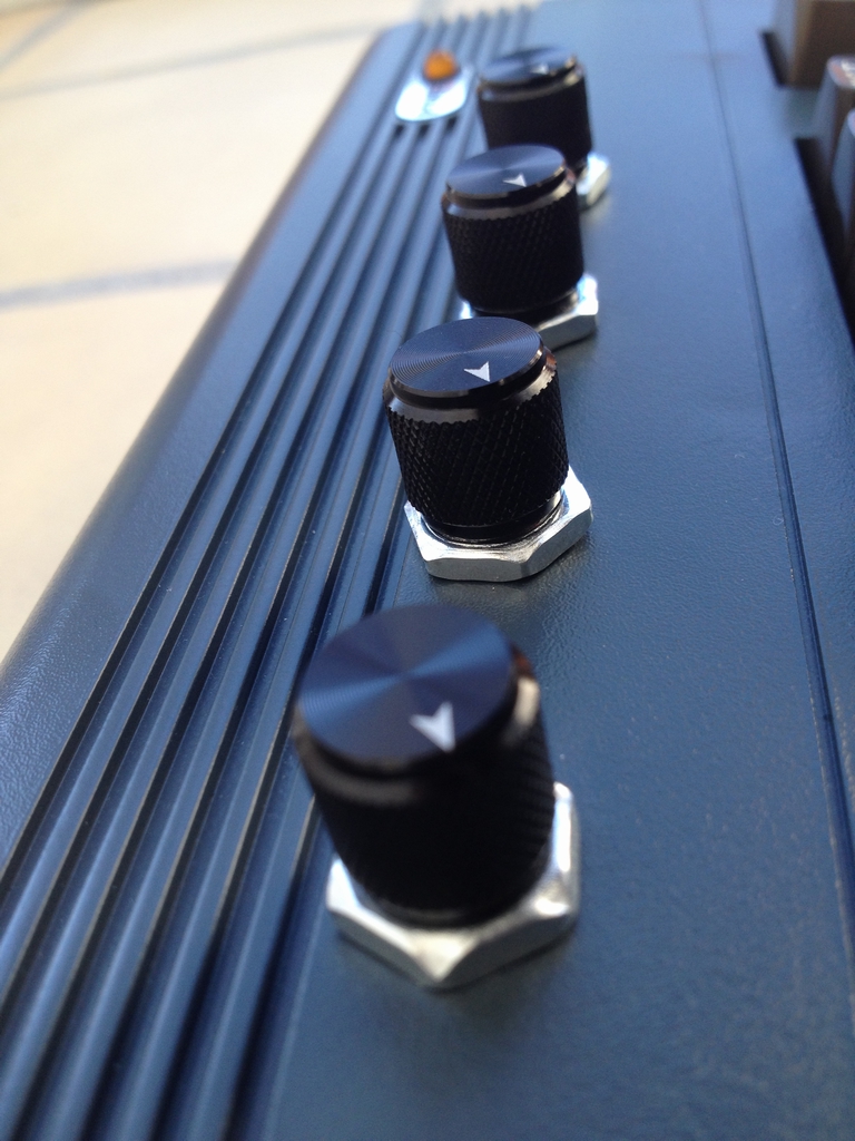
The machine has a sid2sid pcb installed so I can play stereo SIDs from the HVSC SID collection. To connect both channels (left & right) a pair of stereo phono RCA jacks have been mounted on the back of the case. All I have to do is attach some phono cables to my stereo receiver and I’m ready to go nostalgic! I also added a new Commodore 64 label from Ebay. On top of the case four potentiometers for controlling music carts like Mssiah and the CynthCart have been added.
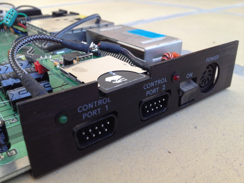
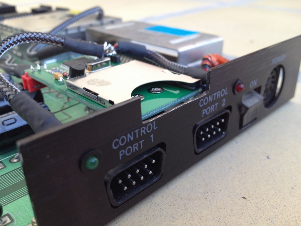
Internally installed SD2IEC PCB for all my gaming needs. The SD card can be inserted/released without opening the case. The green and red LEDs (disk activity and disk load error) have been mounted to the metal bracket as well.
I still have to make a 3D domed sticker for the bottom, but having just a few copies made is ridiculously expensive! I hope to find someone who will print them at a reasonable price in 2016.
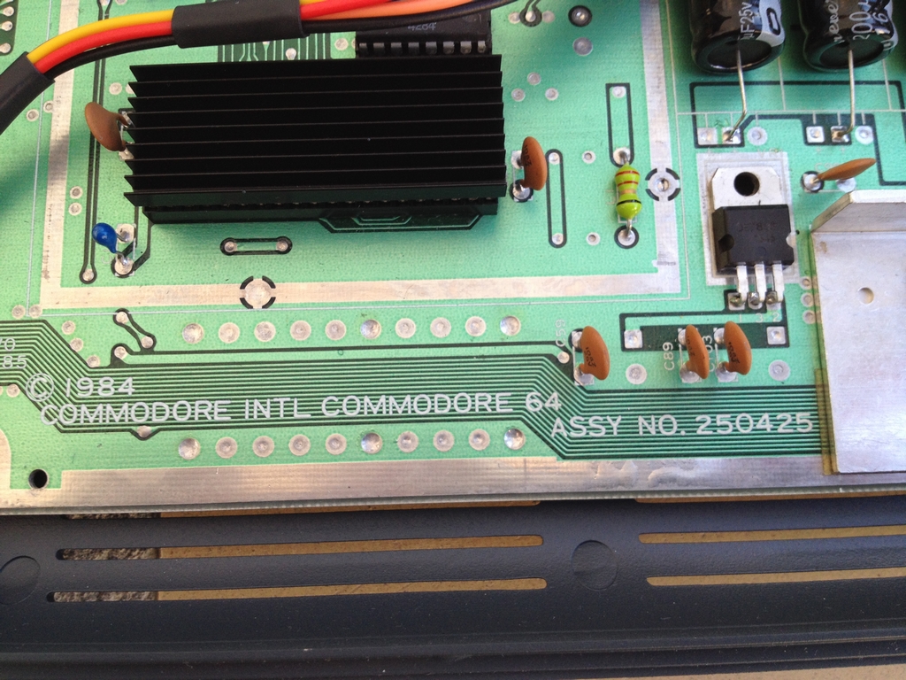
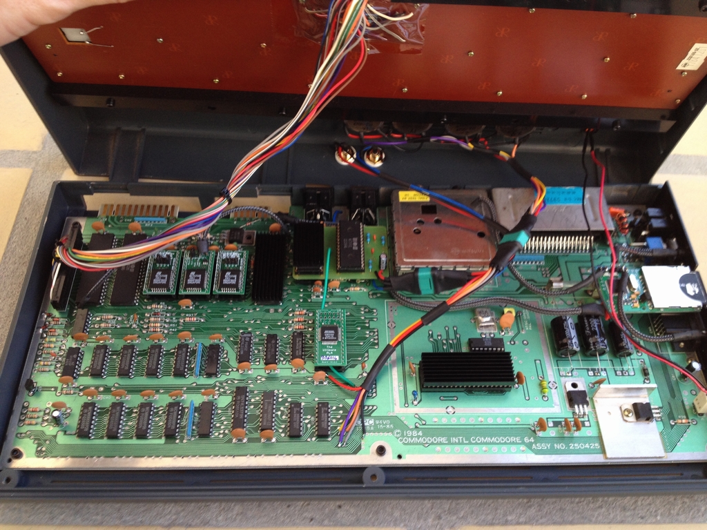
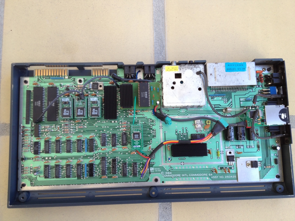
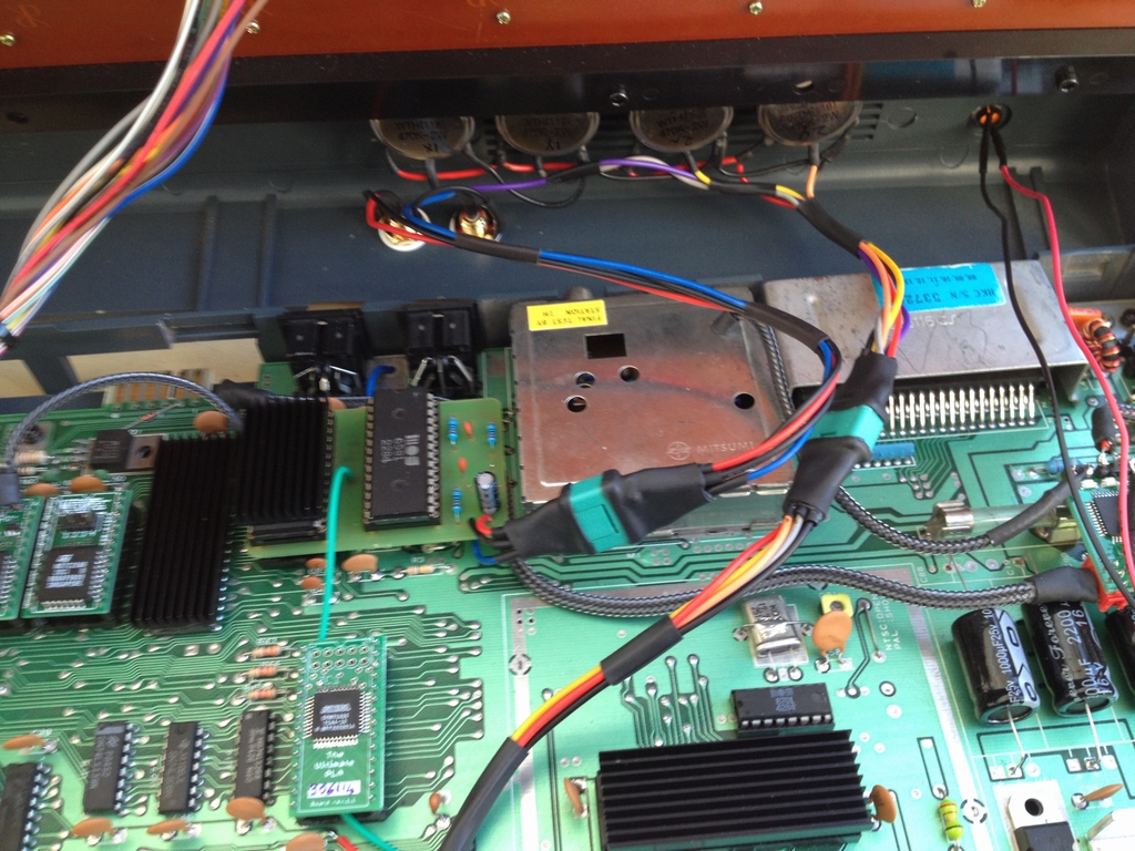
The PCB is an Assy 250425 Rev. A and it is in pretty good shape. This is the inside of the machine. I have tried to make the cable mess as neat as possible.
SD2IEC Mod
The SD2IEC is a mass storage device which uses a SD card for data storage (i.e. games and programs) and interfaces with the IEC bus. The most common use of the SD2IEC is as a replacement of a Commodore 1541 diskette drive. It does not emulate the diskette drives completely like the 1541 Ultimate II, but it reads quite a few .d64 and .prg files. And most importantly, it supports JiffyDOS natively!
I got the PCB from thefuturewas8bit which carries it in various versions (internal & external cased versions). I wanted an internal install of the SD2IEC and I did not want to make any cuts to the case itself. I found the best location to be at the metal bracket between the joystick ports. A small rectangular piece was cut out to make just enough room for the device to stay clear of the top part of the case.
The internal install version has a pin header for attaching a disk swap button and two LEDs (usually a green and a red). The disk swap button is essential whenever a game comes on more than one disk. Pressing the button will swap the disk and automatically load the second disk. To use this feature, special files must be created and placed in the specific game directory. To reassemble the diodes of the original Commodore 1541 Diskette drive I installed a red LED which flashes whenever there is a disk load error and a green LED which shows disk activity.
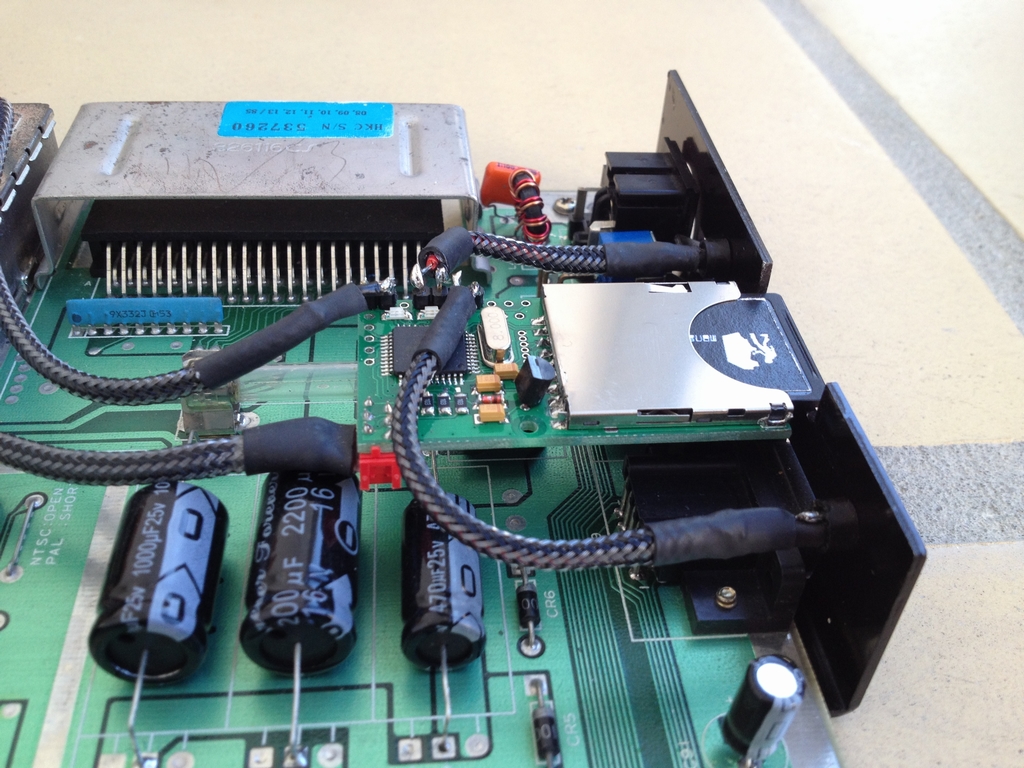
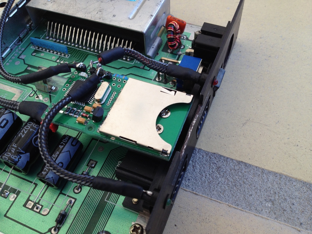
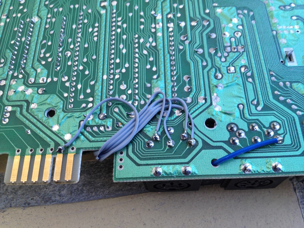
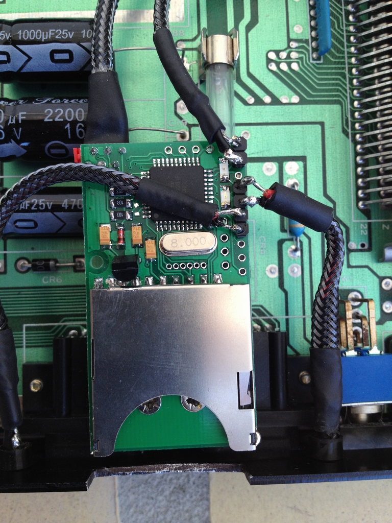
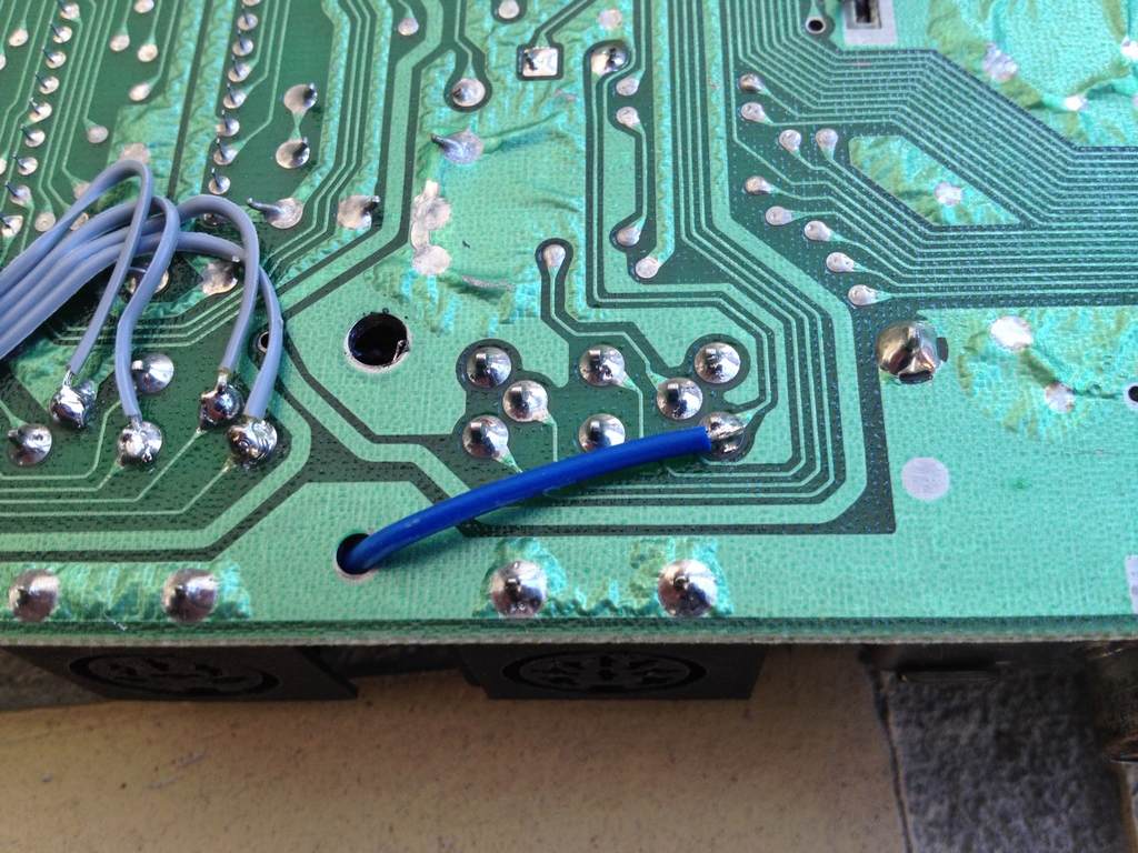
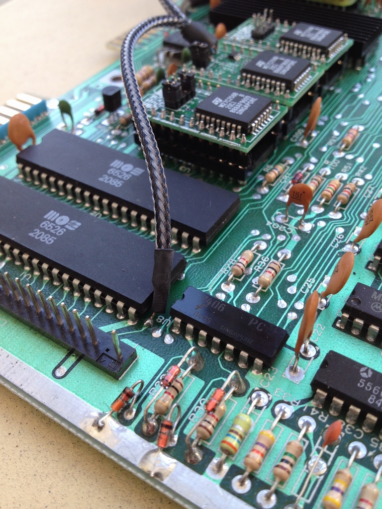
The SD2IEC must be soldered to the 5V+, Data, CLK, ATN and Ground lines of the IEC (Serial Port). The grey wires are all for the SD2IEC, while the blue wire is the sound signal for the SID2SID stereo connection. The SD2IEC is fixed to the motherboard using the screw holes for the joystick ports. Two plastic spacers were used to get the position of the device correct.
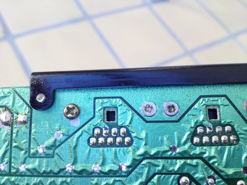
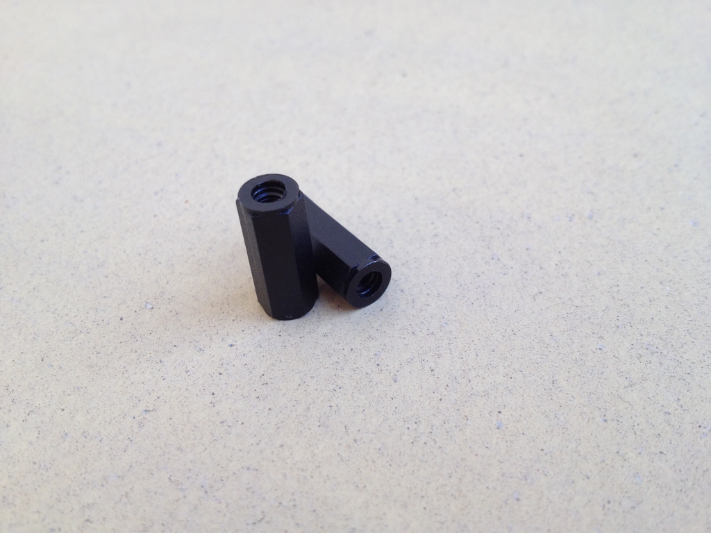
Two small screws were used to tighten the PCB to the spacers. The SD2IEC comes with two holes already made. However, to get the screws into them, the SD-card slot has to be removed. It took me 3 SD2IEC PCBs before I got reassembled one that would actually work after the operation – so do this mod at your own risk! Here is an image of the spacers mounted between the SD2IEC and the motherboard.
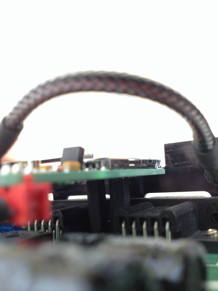
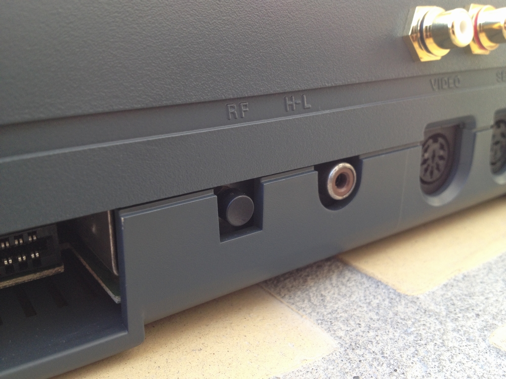
The disk swap button goes out the back at a non-occupied hole next to the RF-antenna plug.
SIS2SID Stereo Mod
To enjoy stereo SID tunes, an additional SID audio chip must be installed into the Commodore 64. The SID2SID Circuit Board is the easy way to achieve this. The board costs 4.5 US$ and can be bought from here. To finalyze the board a few electrical components must be soldered on to it. These can either be bought as a kit from Shareware plus or as I did on Ebay from China. I highly recommend buying the kit as buying all components seperately cost approximately the same but without the hassle.
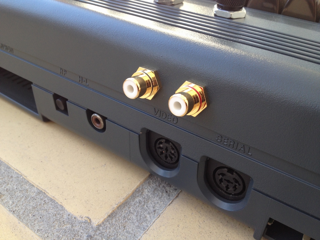
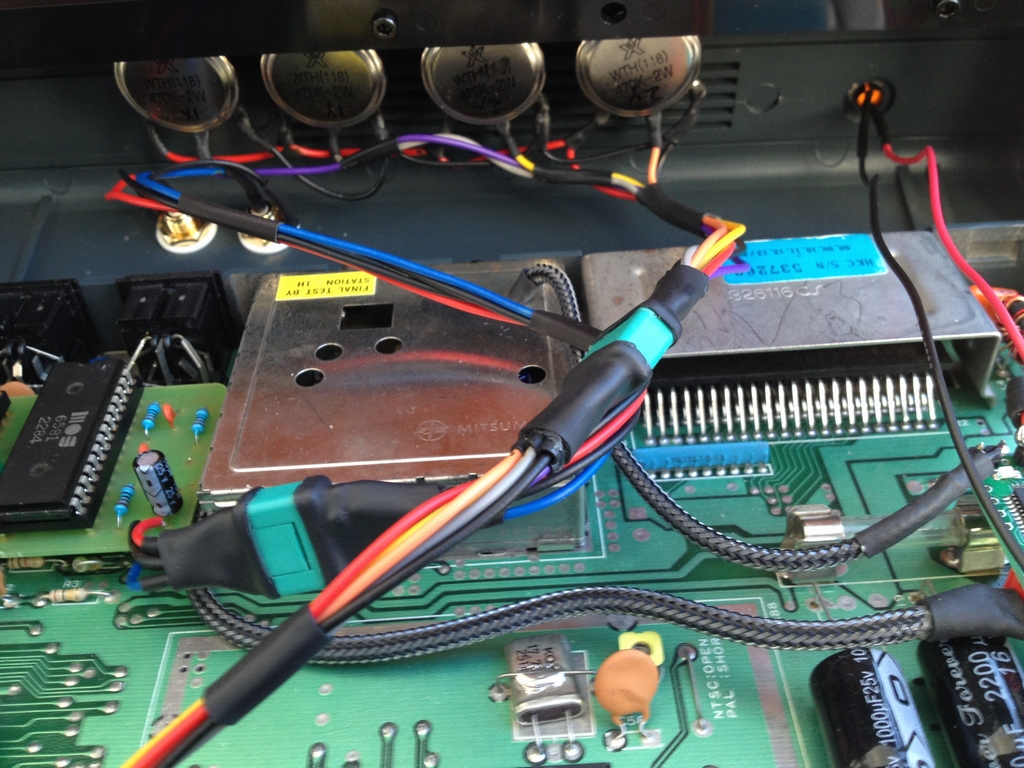
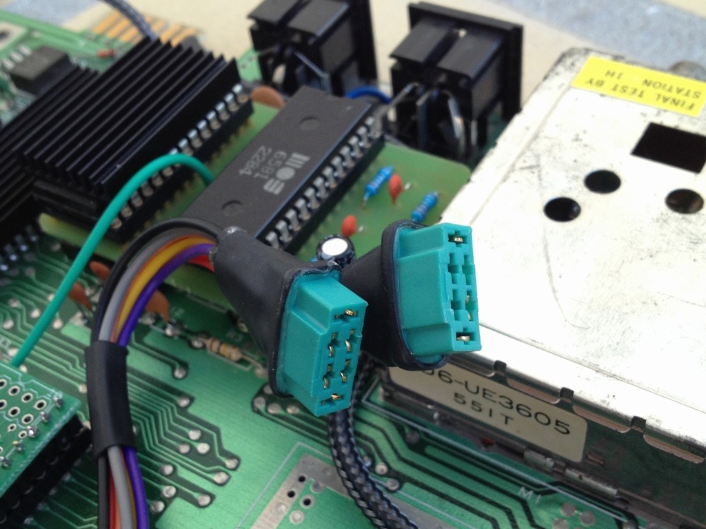
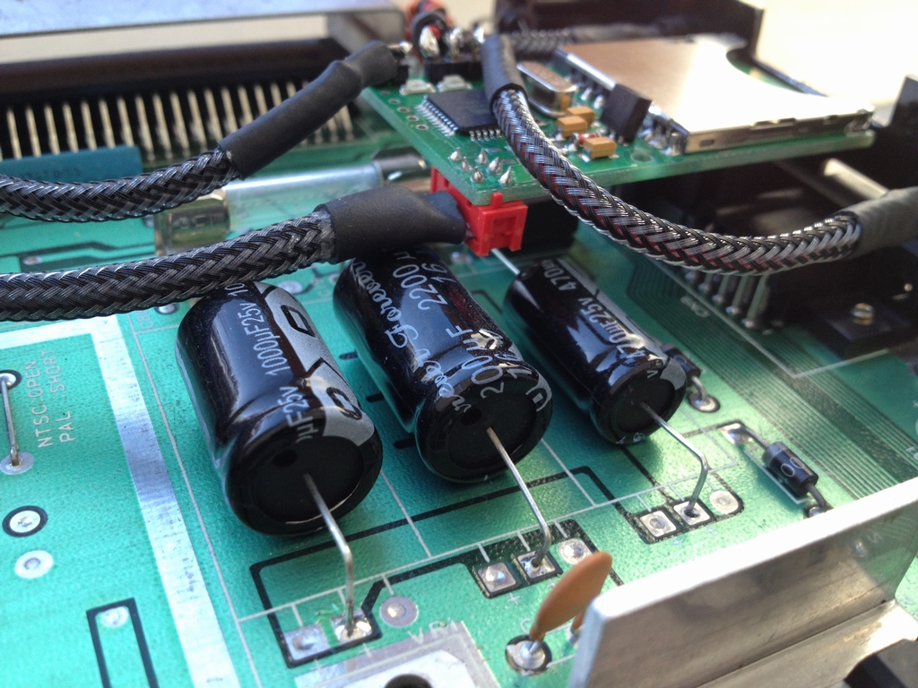
Two golden phono RCA sockets (left and right channels) were drilled into the case on the rear side. Looks alot more expensive than they actually were! The signal line from the primary SID (SID #1) was found on the backside of the PCB and soldered to a green connector (blue wire). The green connectors have 6 pins and are called ‘MPX’. They are produced by Multiplex and are usually used for servos on remote controlled aircrafts and helicoptors. The red wire is from the second SID chip (SID #2) while the black is common ground.
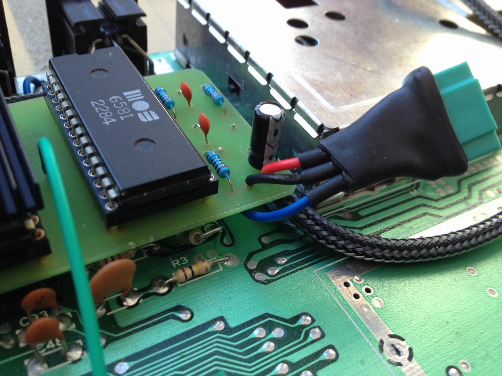
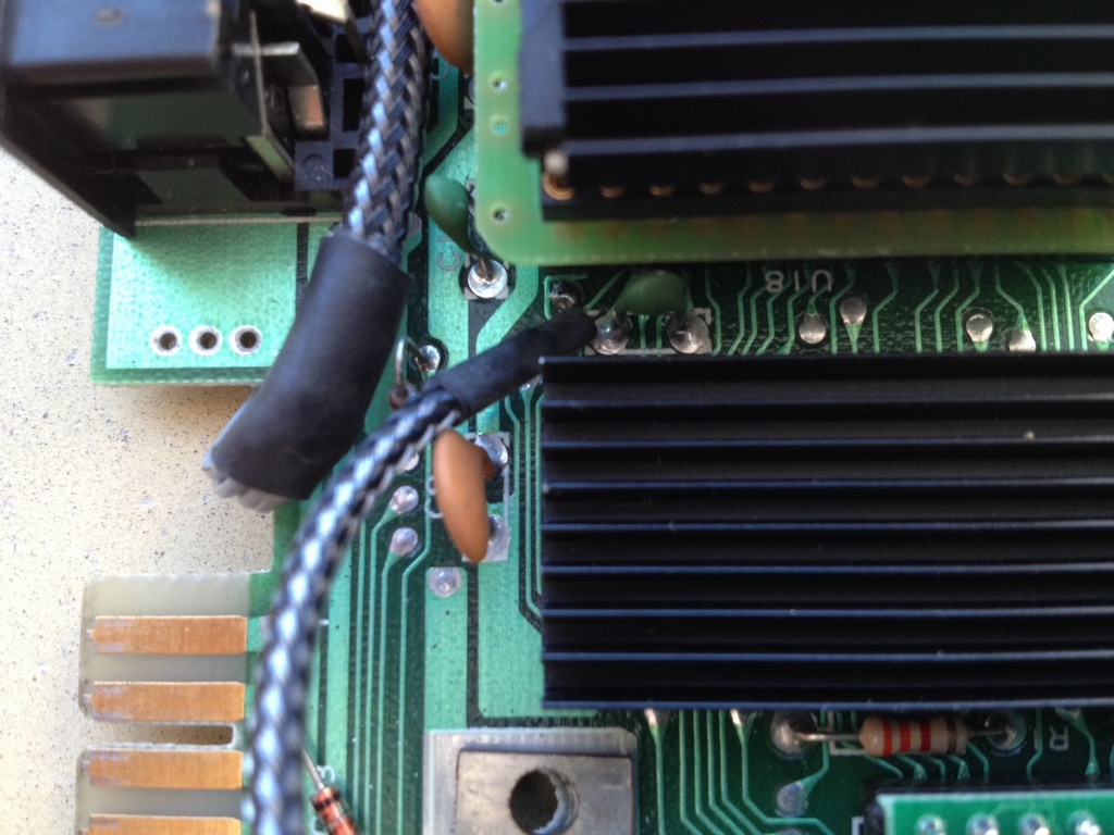
The Cable Select (CS) line of the SID2SID (green cable) must be soldered to pin 7 from the left on the backside of the Expansion Port (aka the Cartridge Port).
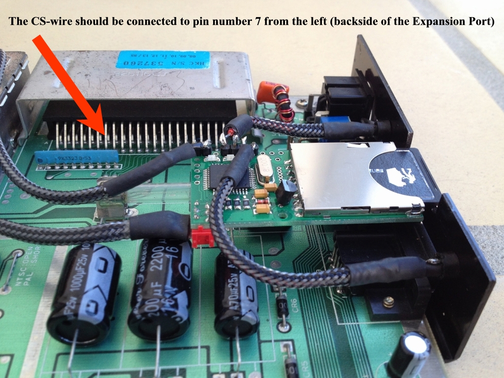
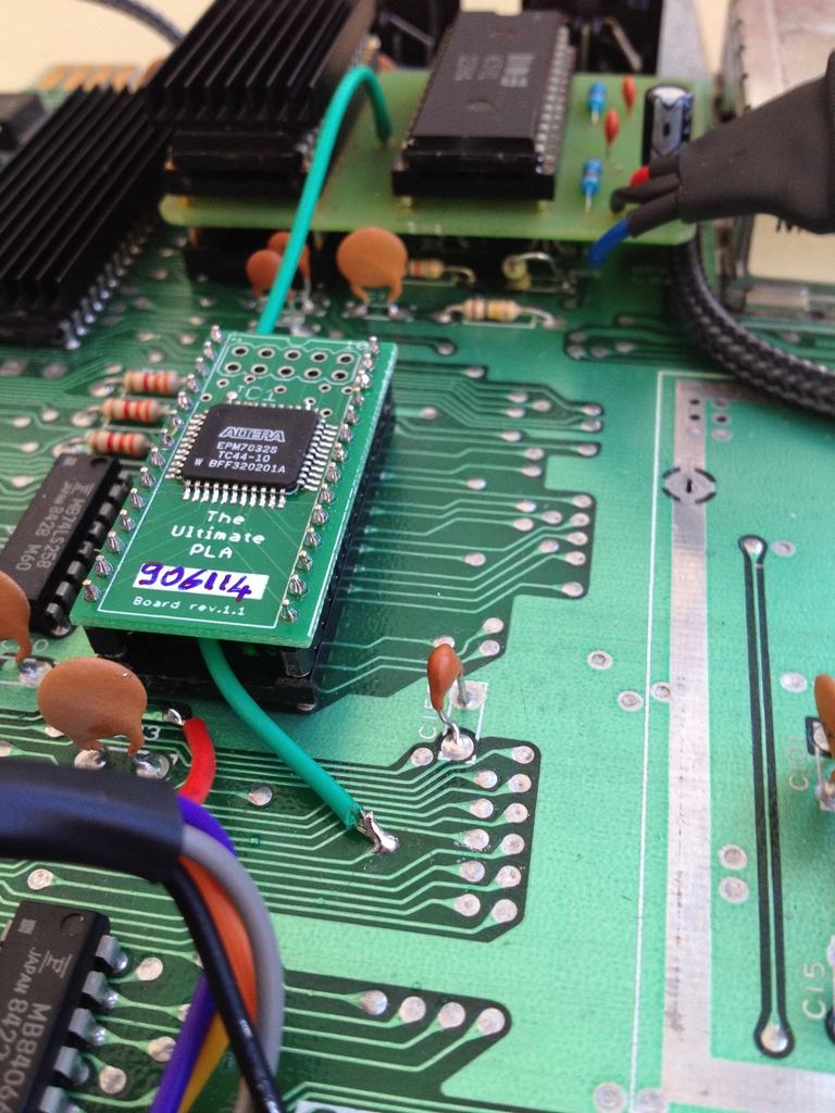
However, as I like to keep things neat and tidy I tracked pin 7 to another location on the motherboard and soldered the wire (green wire). The location is close to the PLA chip.
And finally everything is connected.
Potentiometer Mod
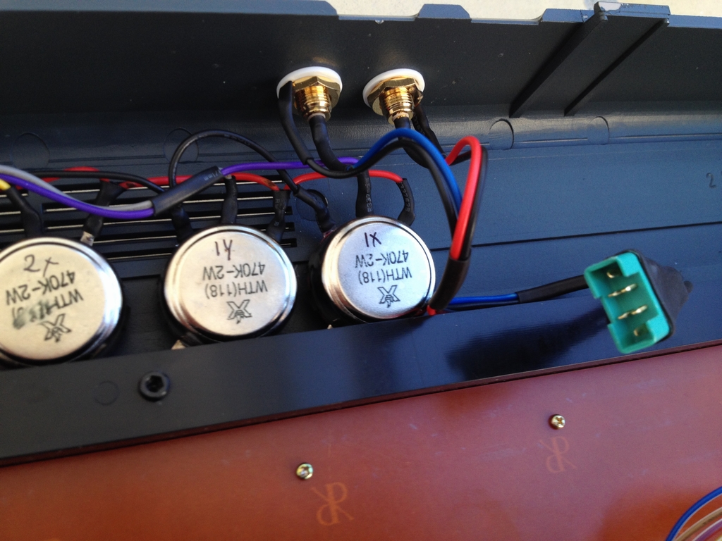
Four 470 KΩ potententiometers, that I got from China on Ebay, have been put on top of the cabinet. They are mainly for music programs like the Mssiah or CynthCart, but they’ll work with paddle games as well.
The inside of the case. All wires have been connected using a MPX plug.
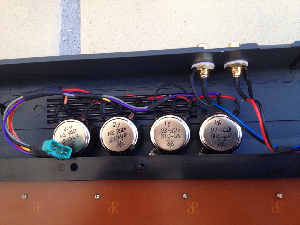
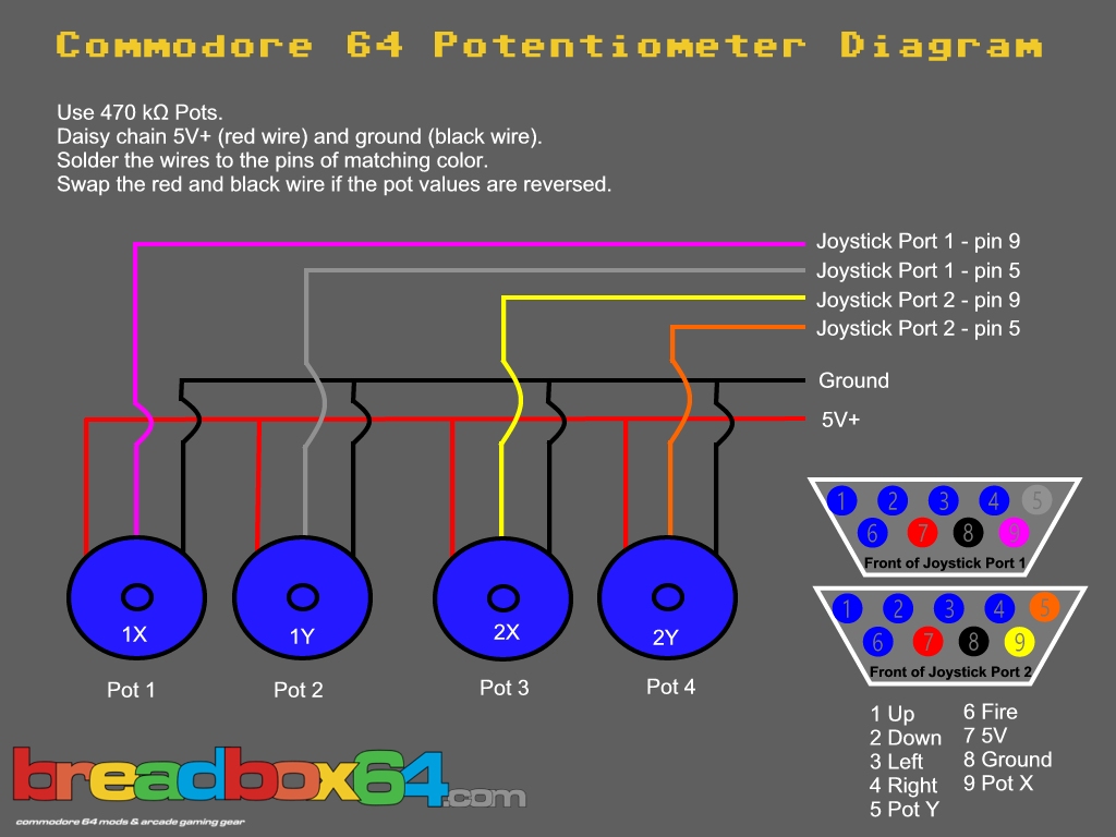
This is the pinout I used to solder everything together. The potentiometers need 5V+, Ground and a ‘pot’-channel which can all be found at the joystick ports.
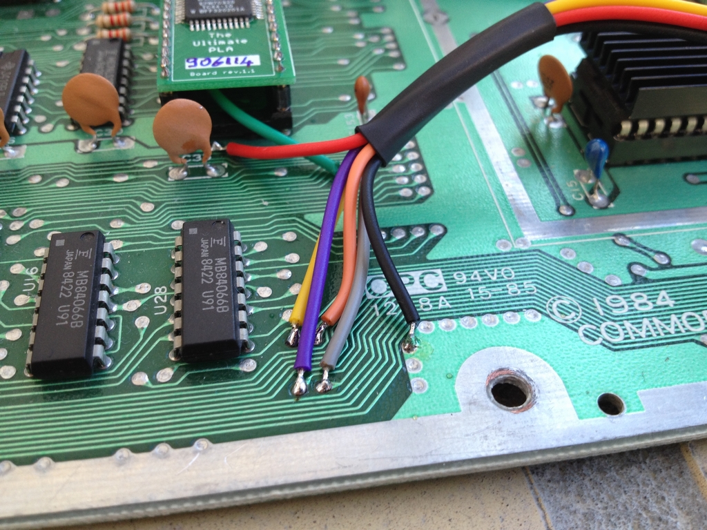
However, as the area surrounding the joystick ports is quite busy with the SD2IEC board, I therefore tracked each line from the joystick ports to a more deserted location on the motherboard. On the Assy 250425 boards, this could be near the PLA chip. The red wire shows where I found the 5V+ line.
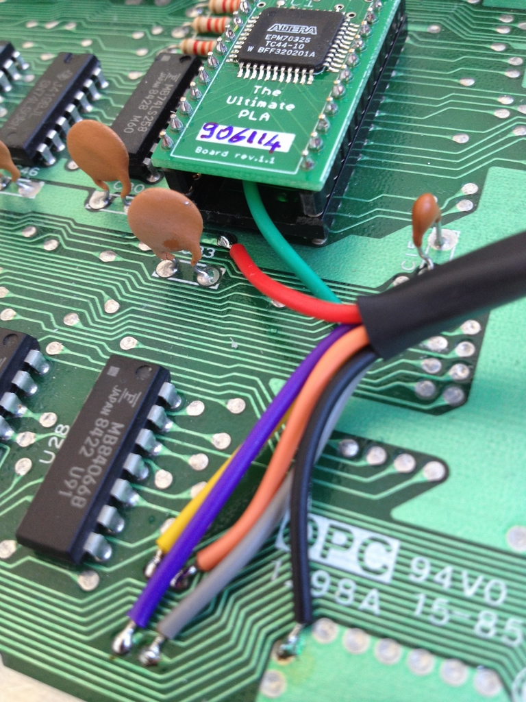
And here are the spots for the Ground (black wire), Pot 1X (purple wire), Pot 1Y (grey wire), Pot 2X (yellow wire) and Pot 2Y (orange wire).
The green MPX connectors have 6 pins which match the number of connectors needed for the mod.
JiffyDOS & ROMs Mods
Three precision sockets were soldered in to easily swap the Basic, Kernal and Characters ROM ICs. The middle IC (the Kernal ROM) have been replaced by a small PCB (switchless kernal) with both the original Kernal and JiffyDOS included. Pressing the RESTORE button during power up will boot the system into JiffyDOS. If nothing is pressed during power up, the machine boots into the standard CBM Kernal. Again nothing can be seen from the outside of the machine.
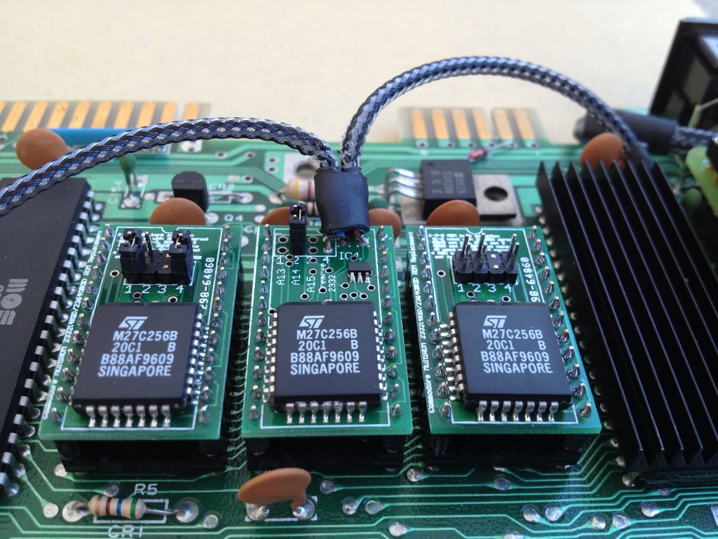
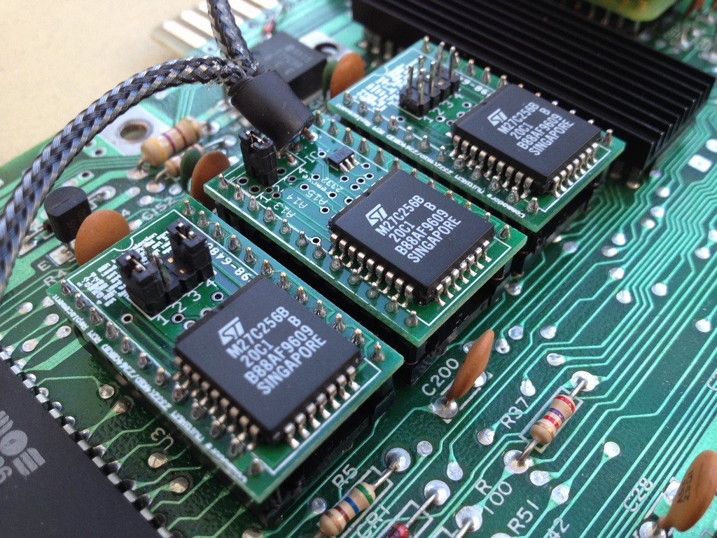
To get the switchless Kernal PCB to work, one cable must be soldered to the RESTORE signal on the motherboard while the other wire goes to the reset signal (pin 40) of the MPU (MOS 6510). The specific solder points can be seen in the pictures.
Capacitors & Voltage Regulator Mods
All capacitors have been replaced as described here. This should make them work for another 30 years without drying out. To be consistent with the idea of replacing all standard electronics which may fail over time, the voltage regulators were also replaced.
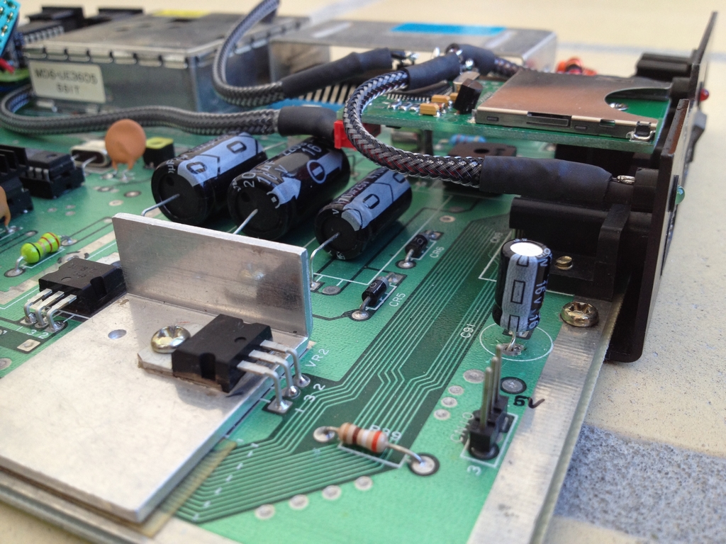
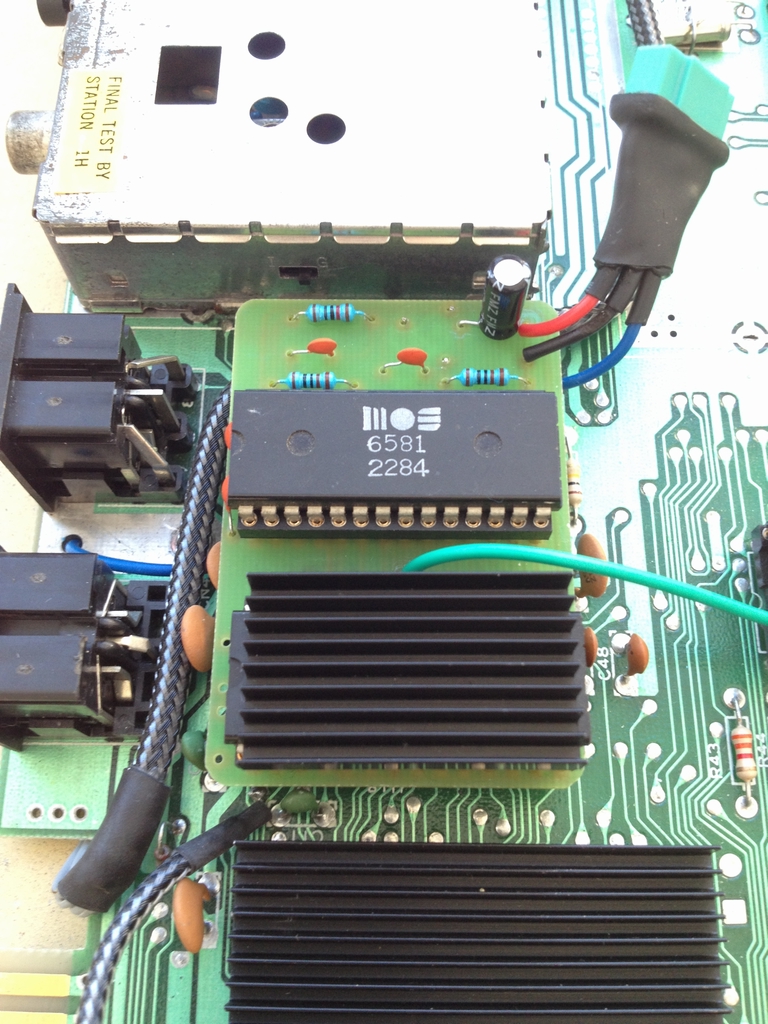
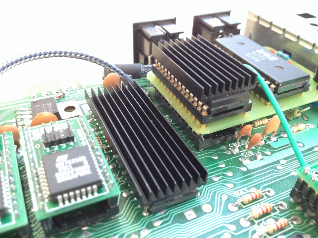
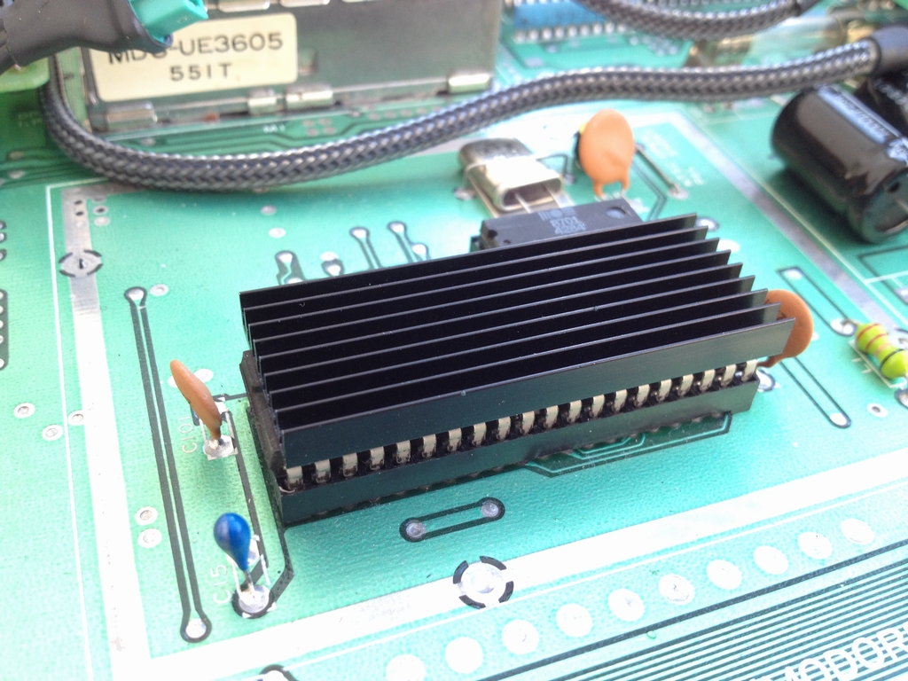
Heatsink Mod
To keep everything as cool as possible I’ve also added heatsinks to all large ICs (SID, MPU, VIC-II). Heatsinks and thermal tape have been bought from the Retroleum.co.uk spares shop.
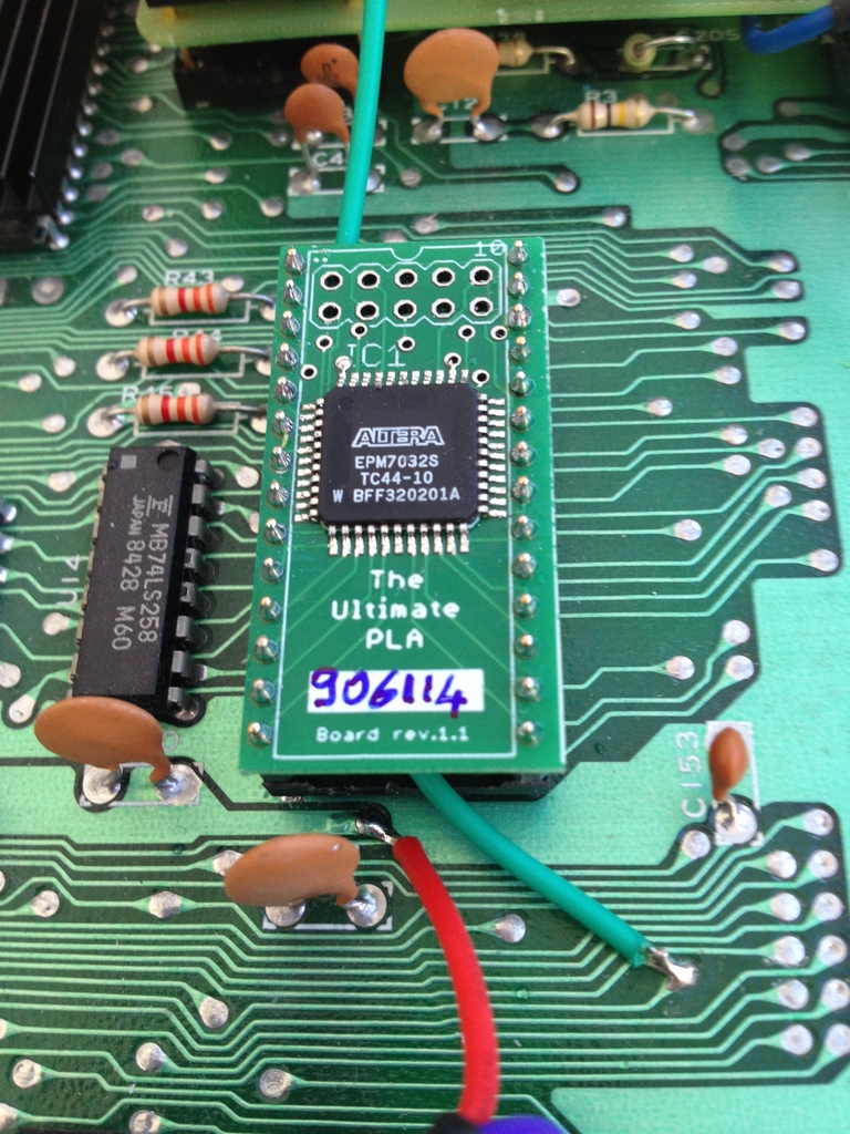
PLA Mod
The board had a black screen at start up when I first got it. It was easily fixed with a new PLA chip (MOS 906114) at U17. The PLA is a new design that I got on Ebay. Contrary to the original PLA, this one runs cool.
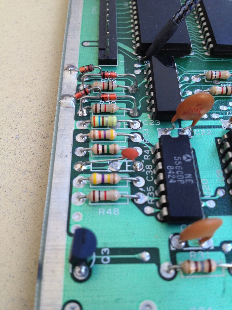
RESTORE Key Mod
On the old long boards of the Commodore 64, the RESTORE key needs to be hit really hard to function due to a misdimensioned capacitor at C38 also known as the ‘NMI Capacitor’. On the new short boards, the problem was fixed. If the original capacitor of 51 pF is exchanged by a 4.7 nF one, the RESTORE key functions as well as all the other keys of the keyboard. The capacitor at C38 was replaced as described here.
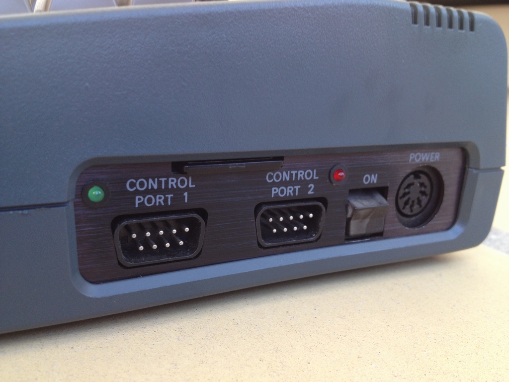
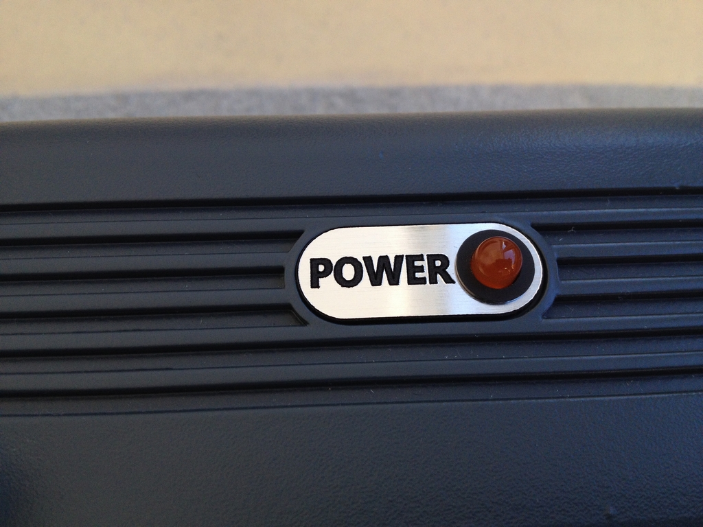
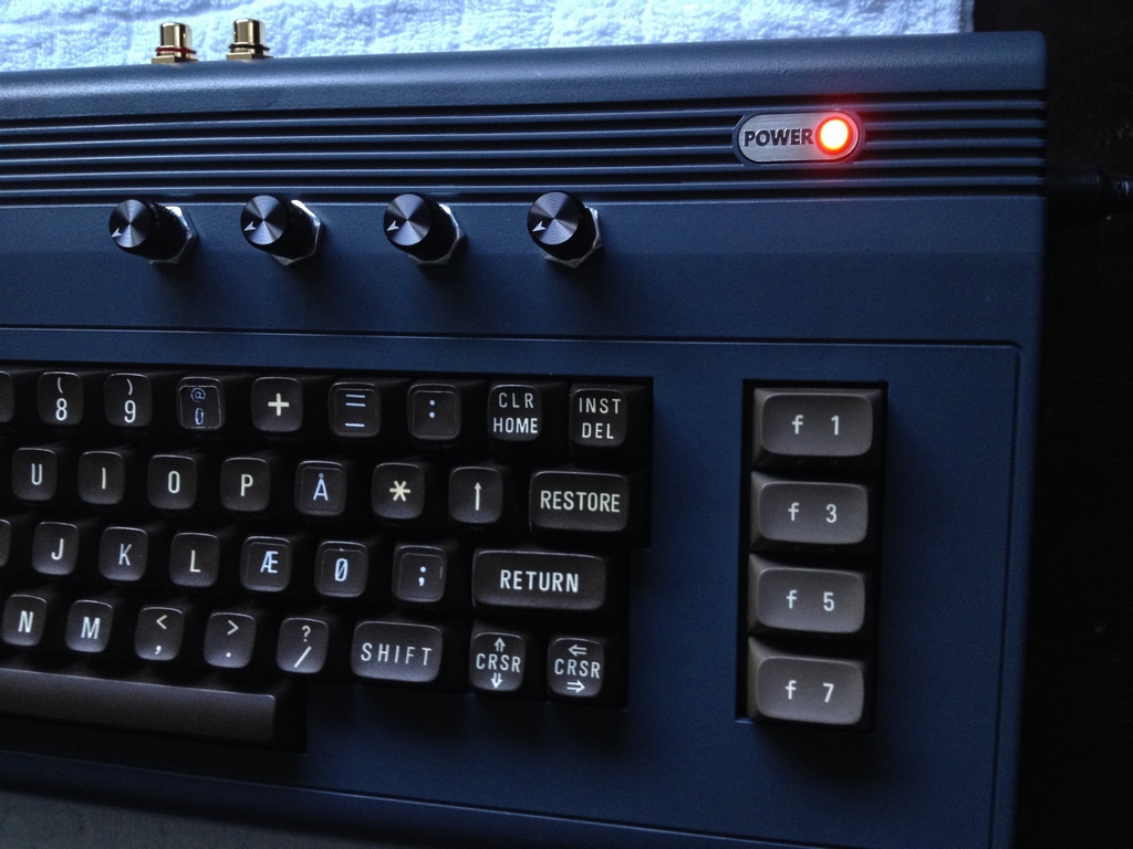
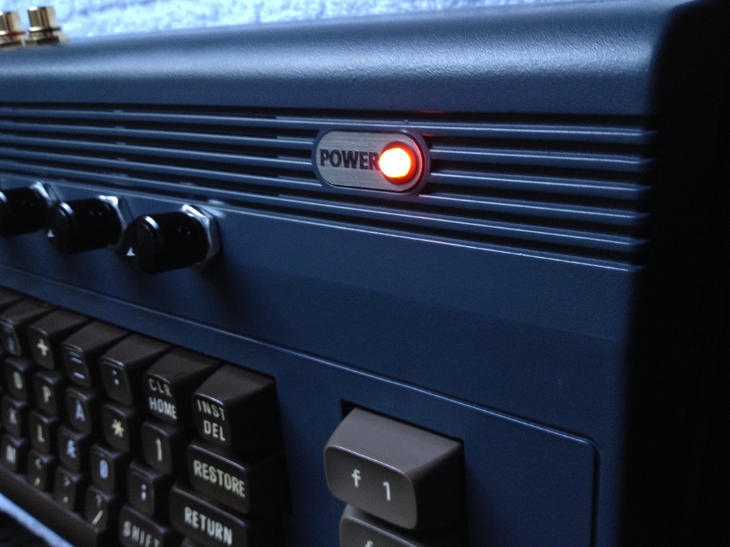
Power LED Mod
An orange LED was added to the case as described here. The orange color actually looks a lot cooler in real life…
And that’s it! Hope to see you back in 2016!
© breadbox64.com 2015
This is amazing work, really fascinating.
Hello Mike and thanks! Happy you enjoyed it!
Very nice mod, love the placement of the sd2iec an its LEDs. It would have looked even better if the pots where fastened on an added plate inside the shell so there was only the knobs on the outside and not the nuts as well – same goes for the RCA connectors, would have looked nice countersunk.
Love the color, looks a little blueish in the pictures (at least on my screen) but I guess it’s just dark gray?
Thanks e5frog! The placement of the SD2IEC is what I think turned out the best in the mod.
You are touching a bit of a delicate topic with the pots as I actually did make a plate for an internal install. However, the attachment of the plate was a little tricky (at least for my building skills) as I found that hot glue would be the best way to fasten it to the inside of the cabinet without having to drill more holes. At that time I already had the RCA connectors mounted (nuts on the outside of the case) and thought I would go with a more ‘rugged’ look for the machine. I therefore ended up placing all the nuts on the outside of the case.
The color of the case i anthracite grey (Molotow spray color #223), which may have a little bluish teint to it, so you may be right :o)
Nice mod. Colour really suits it!
Hey, this is amazing! Would you please post a tutorial on how you made this? Including soldering etc.??
Hi Ben, thanks for the comment. The different mods should be possible to re-create directly from the post 🙂 Some of the mods are described in furher details in other posts on the site – just follow the provided links at each of the individual mods for in-depth explanations. Let me know if you get stuck and I’ll try to elaborate further.
A tutorial on soldering may be better to find on-line. In my experience, soldering is a craft and practise makes perfect 😉 The best way to learn is to get a good soldering iron and some lead-based solder and you should be half way there – the non-lead stuff is really hard to use!
hi, how did you fit the sd2iec over the control ports ? With screws ?
Hi there! The SD2IEC is fixed to the motherboard using the screw holes for the joystick ports and two plastic spacers with machine threads on the inside (link and link). As the distance between the screw holes of the joystick ports and the holes in the SD2IEC device fitted almost perfectly, I used another two screws to attach the device to the top of the spacers 🙂 However, I had to unsolder the SD-card holder to get the screws into the holes. I broke a few devices before I managed to get it working – so be careful if you consider doing the mod!
Thank you for explaining this. I love your mod. It is really high quality and not a cheap looking thing many other people did. Very rare to see mods like you did.
Thanks Alex 🙂 I usually try to avoid cutting in the C64 cases, even though I did in this particular case with the potentiometers and paint. Happy to hear that you liked it 🙂
Hi there, beautiful! Could you please give me the exact brand and color of the paint that you used? I love it! Well done! ?
Thanks for your comment. The paint and color is Belkin Molotow Premium (link), color #223 Anthracite Grey, Art.-Nr. 327148.
Hi! I would like some clarification. I installed the sd2iec to your contacts but when I do the test with the “dead test cartridge”, it gives me an error on the CIA2. Is it normal because I installed a foreign component or risk that with time the CIA2 fails? Thanks for the answer!
Hi Ivan, I don’t think the SD2IEC has anything to do with the error you get on the CIA at U2 using the Dead Test Cart (assuming that you connected all the wires correctly!). Do you have access to content on the SD2IEC? If the CIA at U2 is broken, you will not have any serial port access. Thus, you will have no access to the SD2IEC device or a standard 1541 diskette drive for that matter. Ray Carlsen have noticed that a broken CIA at U2 will produce a normal startup screen, but no serial or user port access. You will also get a ‘file not found’ error when you try to reach the drive. Carts work but characters may show as blocks on the startup screen.
Hope this helps and cool that you’ve installed the SD2IEC inside your breadbox 🙂
Thank you for answering! When I connect the 5V wire I get an error on the CIA2 but I can still enter the filebrowser on the SD2IEC. With the “Dead Test Cartridge” I get a RAM U21 error. With the “computer test” that I run with a MP32C64 Arduino (Tapuino) I connect it to the input of the datassette port and it also gives me an error on the CIA2. Now I connect the same even if performing the test that gives me some errors? or risk that with time the chips CIA2 and the RAM breaks?
It sounds that you may have other issues than the Tapuino and the SD2IEC. Have you run a test cart with a harness that tests the serial and user ports as well? I normally use the Dead Test Cart for RAM testing in blank/black screen machines only and the 64 Doctor cart with a harness/plugs for testing everything else. A test cart that tests the serial port as well could elimate the speculations on the faulty CIA at U2 🙂
Can I use the SD2IEC for the 64-doctor test?
The Trilogic 64 Doctor cartridge comes with plugs for the Serial port (IEC port where the SD2IEC is connected to) and the User port. You need to unplug everything connected to the C64 including the SD2IEC and the Tapuino. You then insert the cart and the two plugs and turn on the machine. The cart will then will perform a range of tests including the CIA’s and the RAM’s. If all tests passes and everything looks fine, then there may be something faulty with your other devices (Sd2IEC and/or Tapuino). The 64 Doctor is just for testing the hardware IC’s of your C64, not for any peripheral that you may have added.
I ran the test with “doctor 64” and the datacassette remains in function. I also tried to change the datacassette and remains always in motion!
You should never run the 64 Doctor with the serial plug and the Datasette simultaneously! It is stated in the manual and writte on the screen when running the tests. You may fry something or get weird unexpected errors. The 64 Doctor is just for testing the keyboard, the joystick ports and the main IC’s on your C64 motherboard. If you get no faults with the diagnostic software, unplug everything and then commence with testing the peripherals afterwards. Do not do it at the same time.
If the cassette deck runs continuously then you may have a faulty MPU at U7 or a blown fuse. The former should be evident from the diagnostics cart while the latter can be tested by testing the fuse on the motherboard.
I resolved the failure. IT was a broken capacitor. The one near the RAM U21. I have another question regarding the SD2IEC. The games take a long time to load. How do I start Epyx Fastload program so that I can speed up the loading of games? Thanks.
Cool that you got it fixed. As far as I know the best way is to get a Epyx Fastload cart and run it from there. You can also consider modding your machine with JiffyDos. This also speeds things up a lot. You can find an example of how it can be done here (link).
Thanks for the answers! I have another problem. Besides mounting the sd2iec I also mounted a reset button. However, when I finish playing I press the reset button but the sd2iec no longer starts. I have to turn off and turn on the computer. Is there a way or command to unmount the previous program/game and then restart another game without turning off the commodore? thank you!
Where did you source the case badges?
Hi Kirk, I got them off Ebay. Search for ‘Commodore 64 badge’ or something similar 😉
Very nice, I tip my hat to You 🙂