
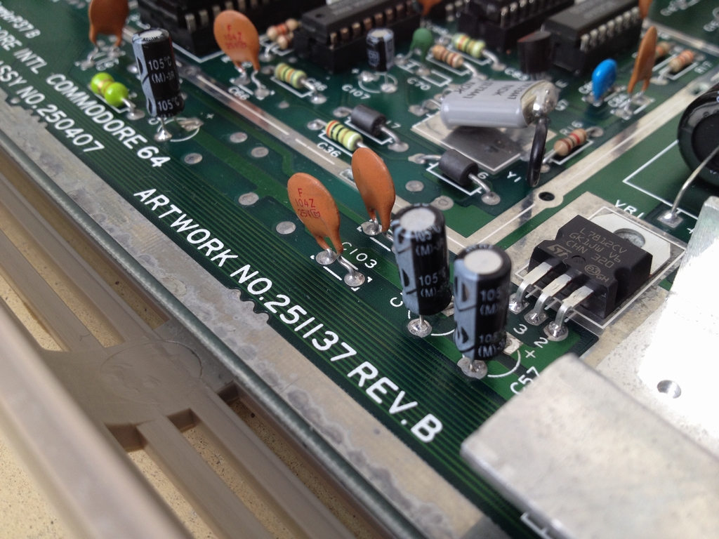
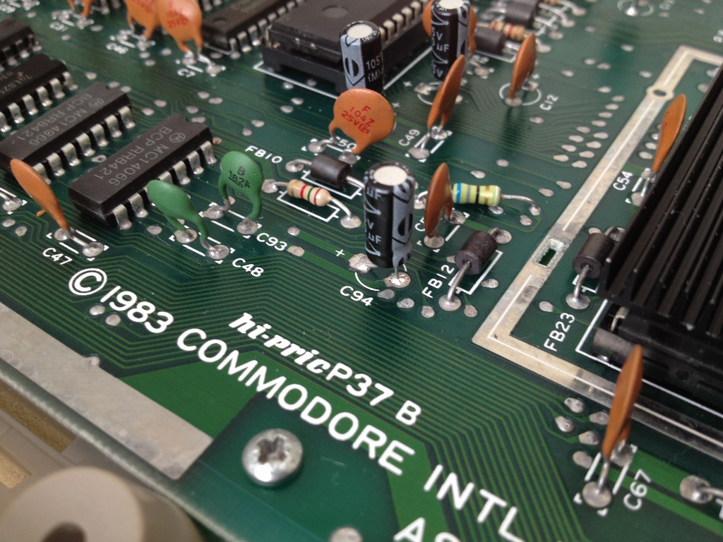
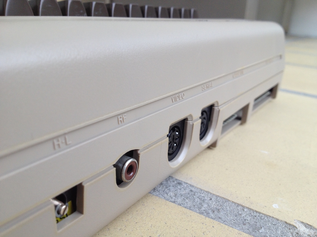
This is a Version A-CR PCB produced from 1983 (known revisions include Rev. A, Rev. B & Rev. C). From this version and forward, the Commodore 64 board had an 8-pin video jack.
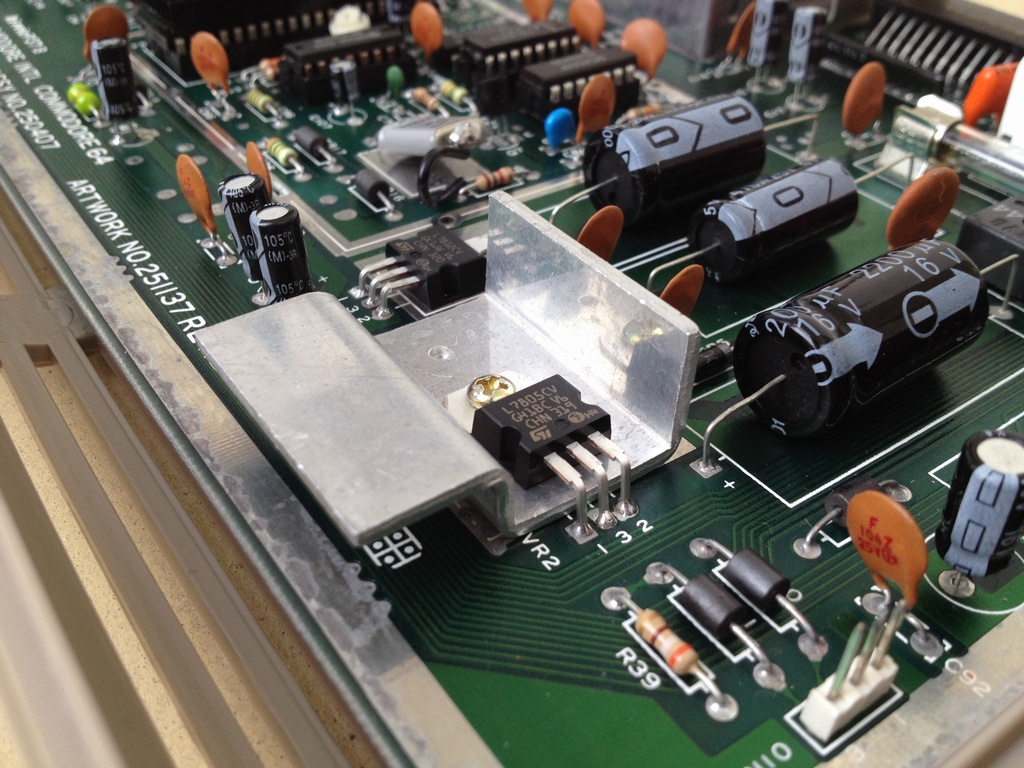
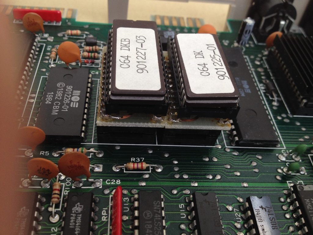
The inside of the machine:
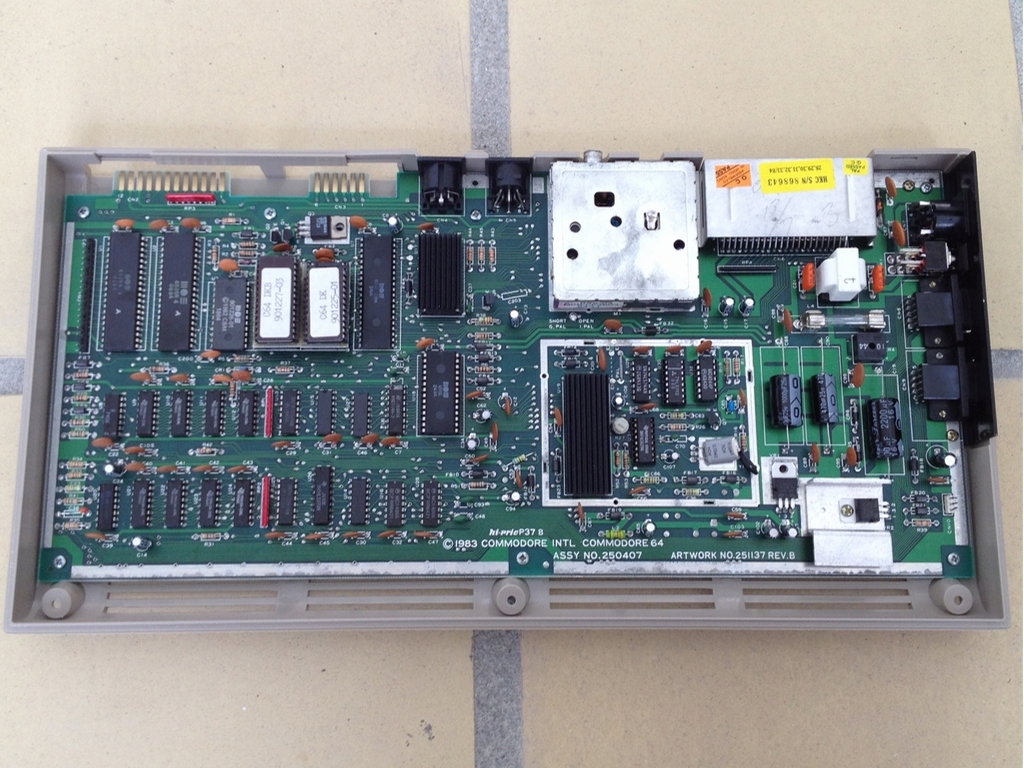
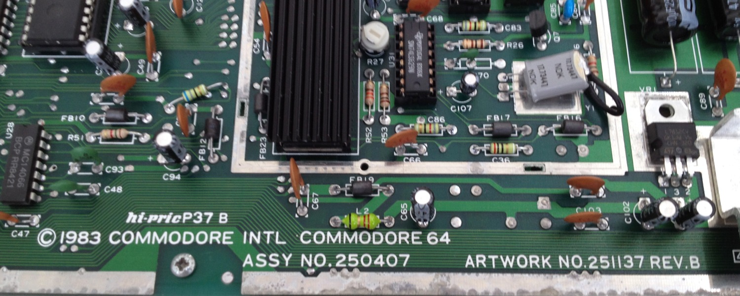
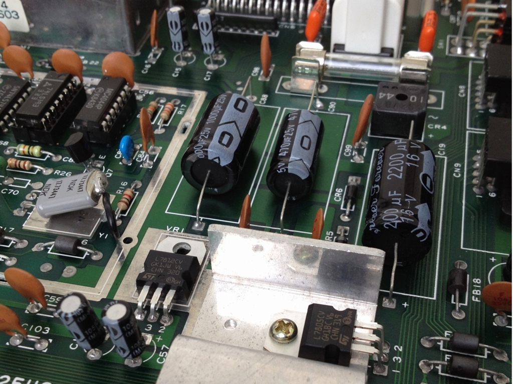
All voltage regulators and electrolytic capacitors have been exchanged for new ones as described in the C64 Capacitor Mod.
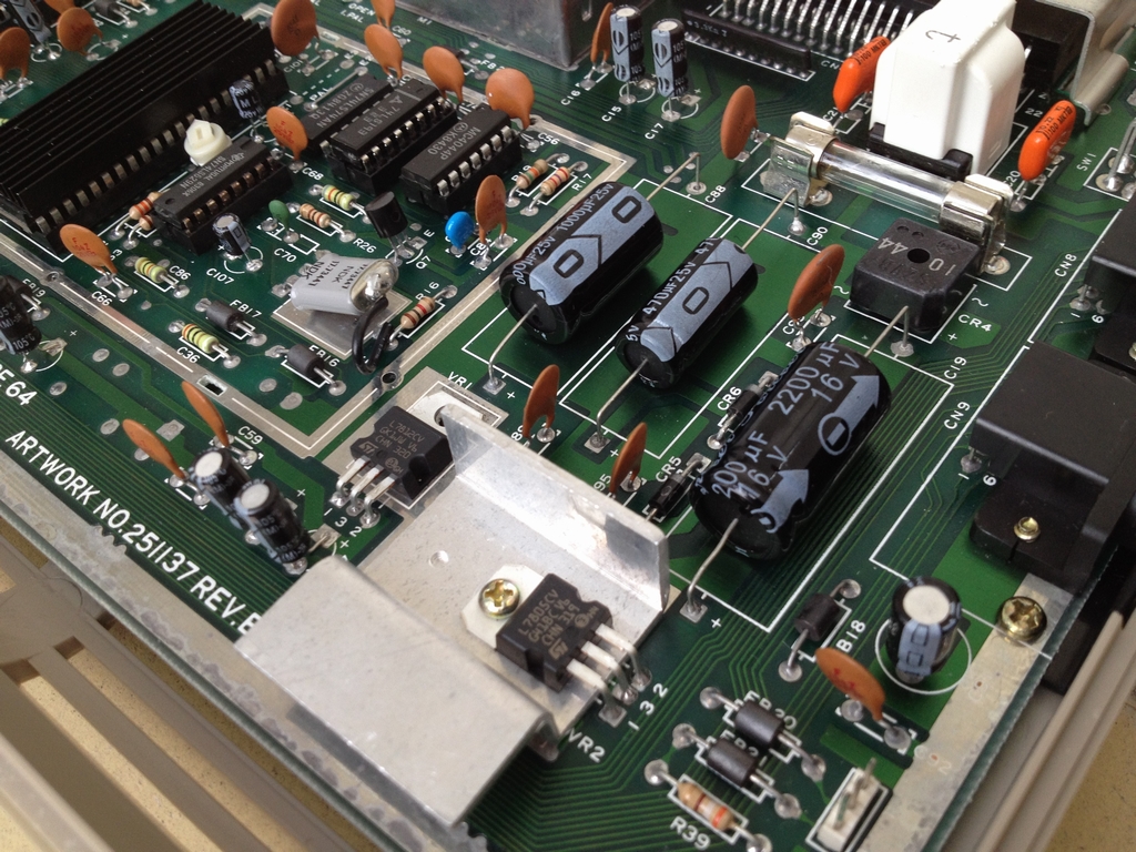
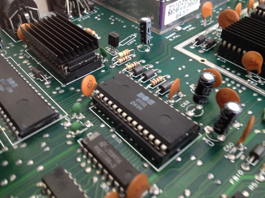
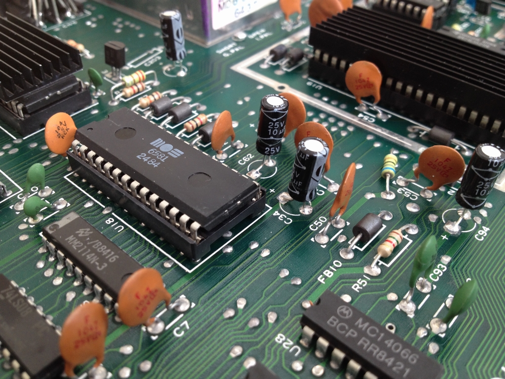
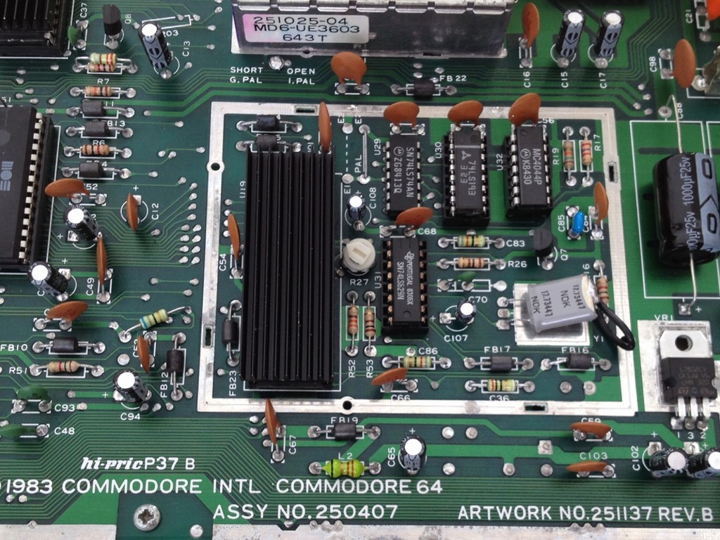
The VIC-II and the PLA chips both have heatsinks attached to keep them running cool. Heatsinks and thermal tape have been bought from the Retroleum.co.uk spares shop.
The machine was originally used at a Danish High School, so the character set has been changed to Danish by swapping the Kernal and Character ROM’s. I’ve had a few of these machines and it seems like the chips and adapters were manufactured by a professional company back in the days.

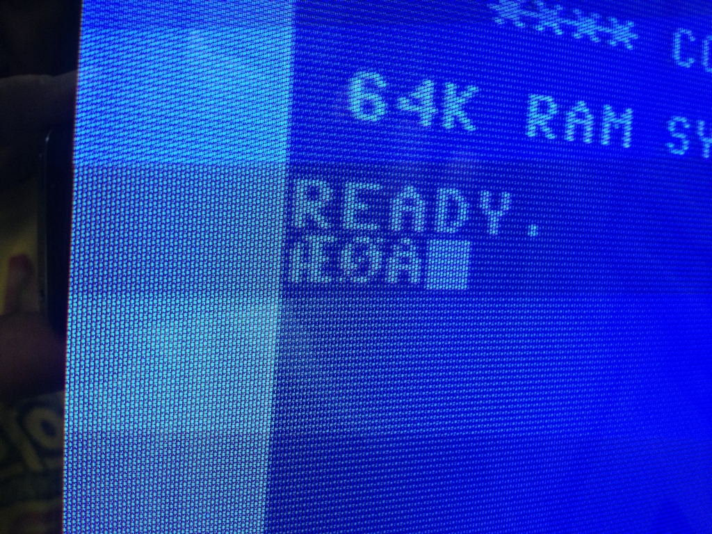
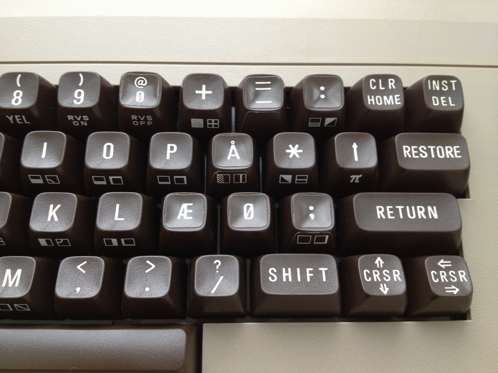
The special Danish characters look like this:
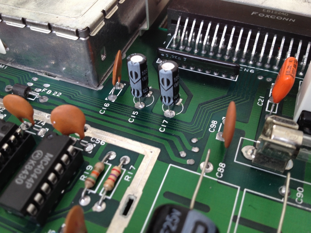
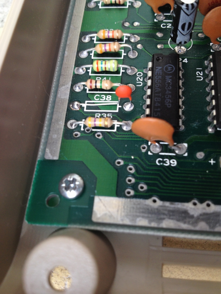
Capacitor C38 (51 pF) has been replaced by a 4.7 nF one to make the RESTORE key work like all the other keys as described in the C64 RESTORE Key Mod.
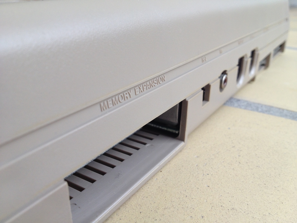
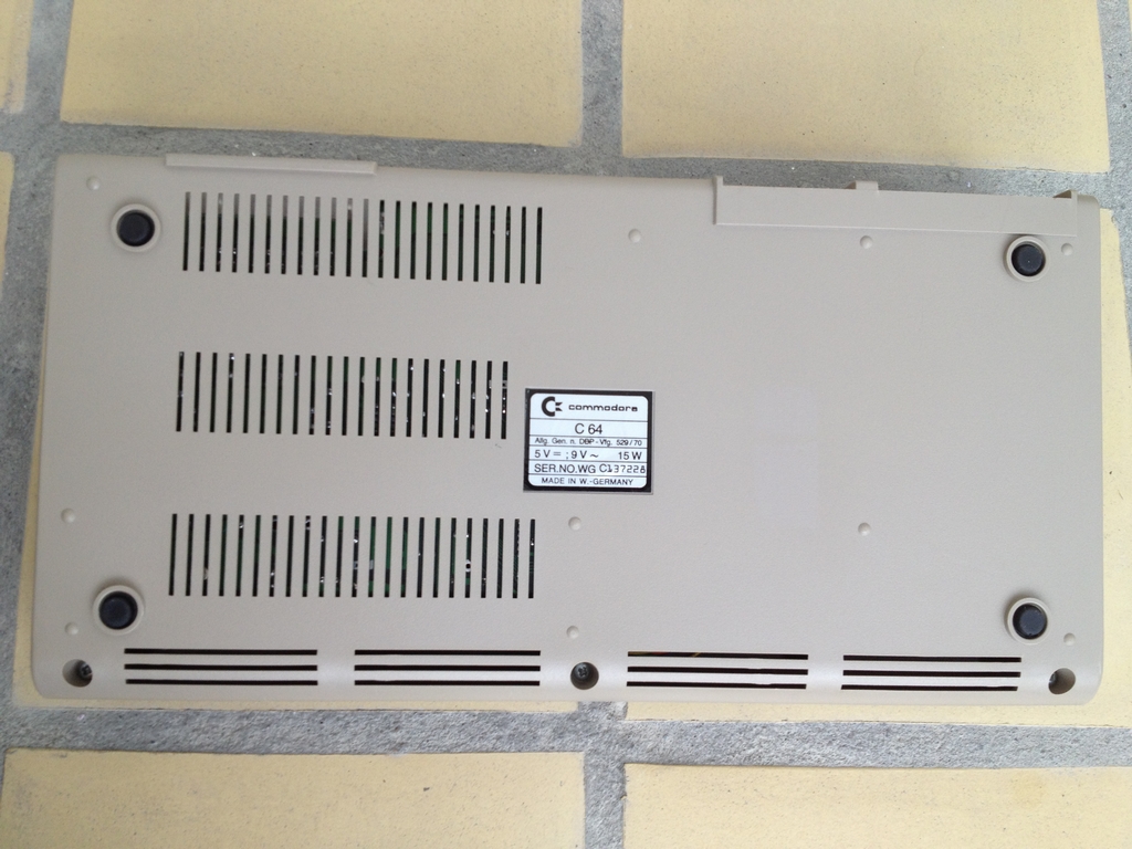
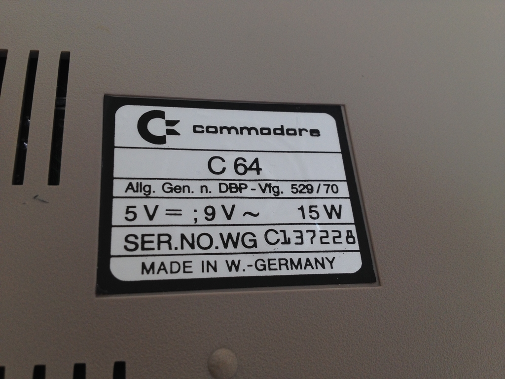
The outside of the machine:
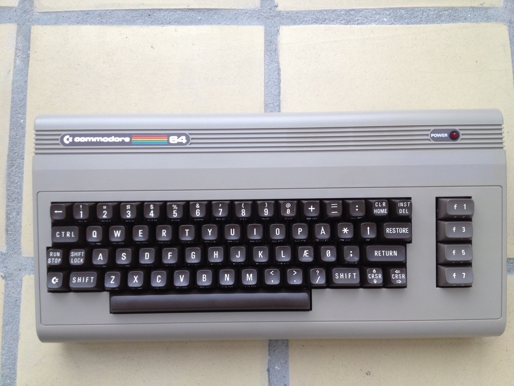
As evident from the labels on the keyboard, the machine has a Danish keyboard layout. Instead of swapping the keys, small labels were added to indicate the new characters.
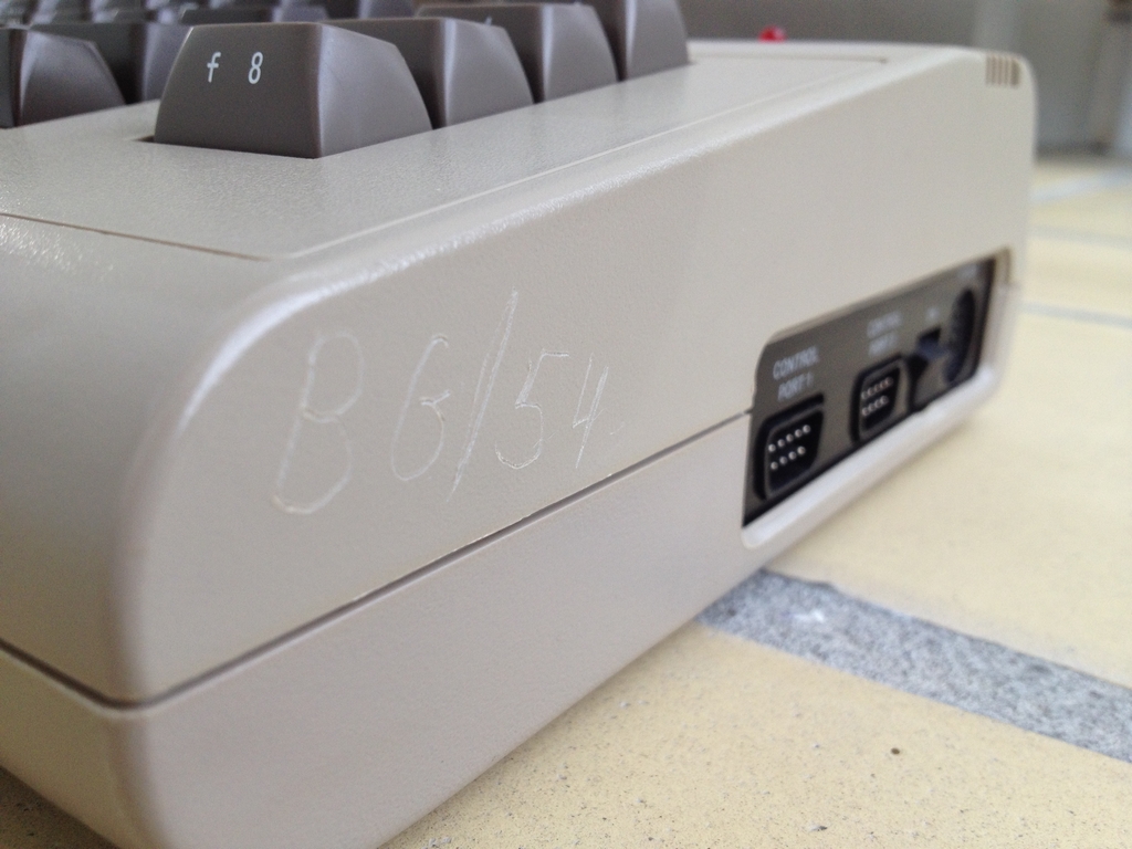
The machine had previously been used at a Danish High School and tagged with the school’s initials and the machine’s number on the side (‘BG/54’). The case is in pretty good shape and the number on the side just adds to the authenticity of the machine.
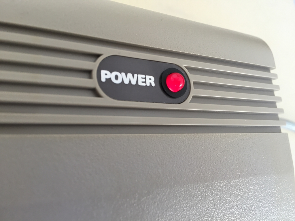
The power LED color is red.
© breadbox64.com 2015
Excellent oldschool computer. We had BBC micro computers at our schools in England in the 80’s. If we had been given C64’s , we would have been gaming all day in lessons 🙂
Thanks Neal! I think we had machines from IBM with green text. If we have had C64’s I guess people would have been more interested in the programming stuff…
Hey MtnBuffalo, very informative post about the board. Some years ago I came into posession of a used C64, with this board revision. You highlight C38 being replaced to fix a problem with the Restore key. However, on the board I have here (just giving it some TLC), C38 has been replaced by a 1.5MOhm resistor… which strikes me as very odd. I’m not familiar enough with the C64 circuits to be able to figure out why someone has done that, or what the repercussions are for running the board in this state.
I was hoping you could help me out here 🙂
Hi SegF4ult. I can perfectly understand your confusion regarding C38. I just realized that almost all my images of it have been taken after I’ve done the Restore mod with the 4.7 nF ceramic capacitor. On the long boards I’ve seen, the original 51 pF is basically a capacitor housed in a green resistor case. In this picture you can see the original underdimensioned capacitor (link). The color coding on it indicates that it is a 51 pF.
As I don’t know what specific component you have on your board I’m just assuming that the component that you have at C38 is a capacitor and not a resistor. However, I could be wrong but think you would have keyboard issues if it was in fact a resistor 🙂
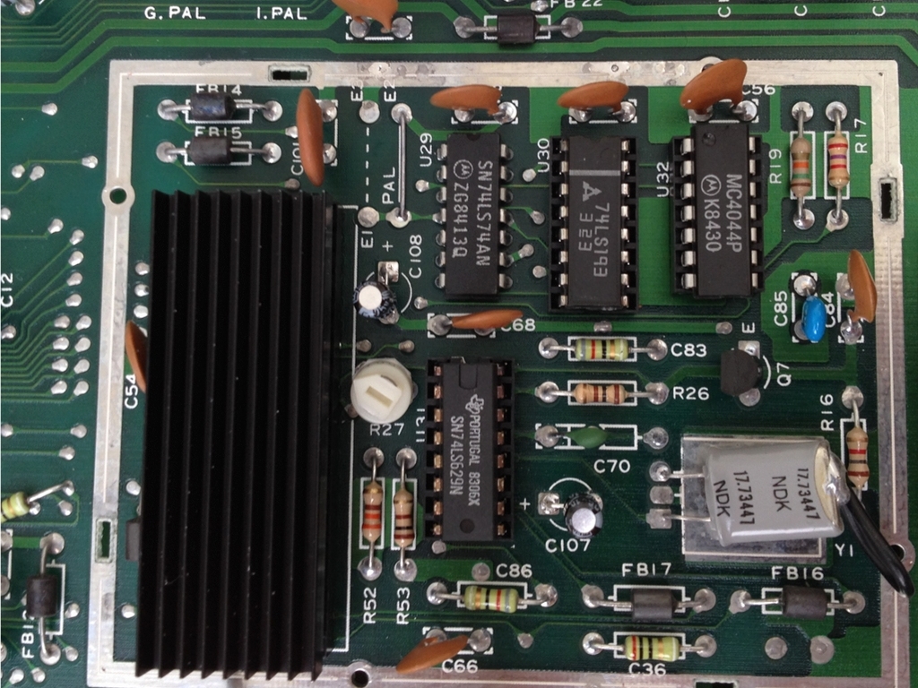
I have a similar board that I am going to completely overhaul, except mine is a W-18 94HB. There seems to be quite alot of variation between “identical” boards. For instance, in my video block, C86 is a mica capacitor but there is a resistor also from it to the trace leading to R53. There are some other idiosyncrasies as well. Did you have similar issues?
Hi Joshua, I guess that is another great example of Commodore basically using whatever they had in stock 🙂
So, the question is now, how would I go about this overhaul? I don’t have the schematic exactly matching this board and have been trying to find an exact match.
When I’m refurbishing a board for my collection, I usually put in new electrolytic capacitors (not the ceramic ones). As it’s a long board I’ll also add a bigger capacitor at C38 to ensure a correct Restore key function. I would also change the voltage regulators at VR1 and VR2 to make sure that the board gets correct voltages. If it’s a board that is going to be used regularly, I’ll also consider adding heat sinks to the larger IC’s like VIC-II, PLA, MPU and SID to keep things as cool as possible. I’ll use some contact cleaner for all the plugs on the rear and test if the Power plug should be replaced. Finally, I’ll give it a good clean 🙂
Oh, and add a switchless kernal with JiffyDos to speed things up!
Thanks for the tips. 🙂 My plan is a little bit different, though. It works (except the SID chip produces no sound, voltages seem right, plugs, continuity, etc) but the previous owner must have stored it someplace where something could dissolve some of the outside of the ceramic caps. When I said overhaul, I meant OVERHAUL :). All components, except maybe ferrite beads as I cannot find those specs, will be replaced by more modern ones (ceramic disk with MLCC, electrolytic with better ones, resistors with better ones, and so on). I found some “drop in” switching voltage regulators to replace the old linear ones. But, yeah, I will get around to doing those mods you mentioned (and replace the SID if it is actually dead). Thanks again 🙂
Hi,
I have a question about this assy… In this early version, there are many ferrite beads that you can’t find in the later assy. I suppose they were put in order to avoid some interferences, am I right?
AND THE QUESTION IS… Does the board works the same, even if you remove the ferrite bead and put a jumper in place, assuming the ferrite beads have no resistance at all?
I bought a SixtyClone PCB but I discovered I haven’t the required ferrite beads… Thank you!
I notice in all your photos of the motherboard that you have removed the “cage” from around the VIC chip and have also removed the shield from under the motherboard. Are those required for RF shielding or does it not matter any longer? I have just acquired a C64 with this motherboard revision and I intend to put heat sinks on all larger IC’s and am concerned if I replace the RF shielding above the motherboard that heat removal from the IC’s would be useless. I do intend to keep the “cage” around the VIC chip but I have removed the 30+ year old thermal paste and replaced it with new thermal paste.
Hi Mike, I believe that Commodore primarily added the RF shields to reduce the possibility of introducing interference to old CRT/tube TV sets. Even though they could be made of metal, they were usually made from tin foiled cardboard wrapped around the motherboard. The carboard definately worked more as an insulator and not as much as a heat remover! This holds true in the early versions of the C64 long boards that I’ve seen. The metal case surrounding the VIC-II did however work as a heat sink.
In later version motherboards (e.g. Assy 250466), the modified RF shields were made from metal and did add some cooling to the larger ICs. E.g. I’ve kept the shield in my Assy 250466 long board (link) as it seems to add some cooling to the chips.
Nevertheless, I usually remove all the RF shielding (top, bottom and VIC-II case) as they seem to work more as insulators than heat removers. At least that in my opinion 🙂 I then add modern-day heat sinks and thermal tape to keep them in place. I have not experienced any burned chips using this approach.
With that being said, removing the top/bottom RF shields and adding heat sinks to the larger ICs and replacing the old thermal paste of the VIC-II cage sounds like a good idea. I’m sure that will work just fine 🙂
Hi.
Back in the 80’s we did not use IBM machines in publich schools. Instead, there were used two different systems from Regnecentralen. These systems were named Piccolo and Piccoline, the latter being the last system they created. The same ideas that spawned these machines to be developed, were essentially the same as the ones from England, Sweden and Norway.
They were extremely well build, even the keyboard were made out of metal.