
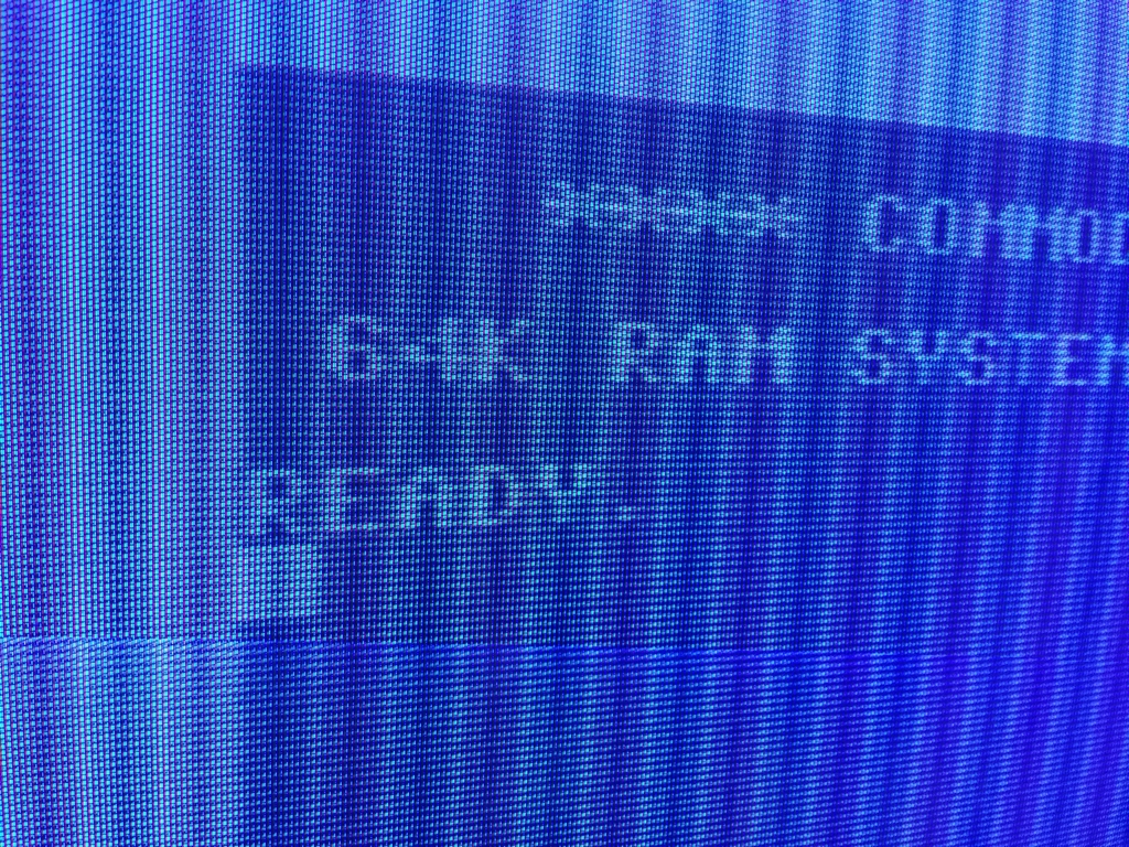
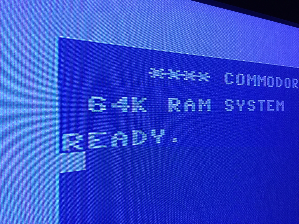
Some people just can’t be satisfied with how things were back in the good old days when Mario was called Jumpman and real computers ran on 8 bit. These high achievers keep tampering with the old hardware to make it perform even better compared to their original form. It was this kind of can-do spirit that instigated some guys on a German Commodore 64 forum to come up with a solution for reducing the inherent ‘clock noise’ of the VIC-II graphics chip and the color bleeding of the S-video signal. The problems are easily recognized in the form of vertical lines (banding artifacts) or as a checkered pattern spanning across most of the screen, depending on the monitor signal being used (Composite or S-video). The issues are not as profound when using one of those good old CRT based televisions or monitors (which some breadbox aficionados think of as being esoteric…). However, when using a modern TV, the effects may even worsen as the video outputs of the graphics chip are not optimized for modern day equipment. The following two pictures show examples of the two types of artifacts.
The cause of the vertical lines artifact is basically unwanted interference generated from clock signals stemming from the VIC-II graphics chip. The noise-introducing-signals include the AEC line (related to bus access), CAS and RAS signals (related to memory access), BA signal (bus availability) and PHI0 (clock related). Practical tests have shown that the primary sources of the interference is intimately connected to the AEC and PHI0 lines and the PHI0 affects the borders more than the AEC does.
The checkerboard pattern artifact (or thin green and red colored lines) is mostly related to the Chroma signal of the S-video output. The problem is most visible when using the Commodore 64 with a modern TV. It can be reduced by adjusting the voltage level of the Chroma signal.
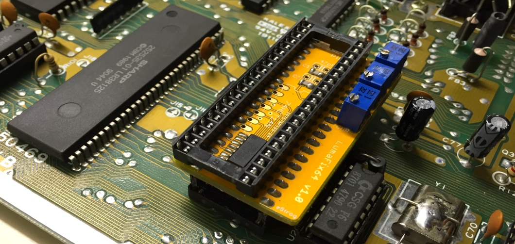
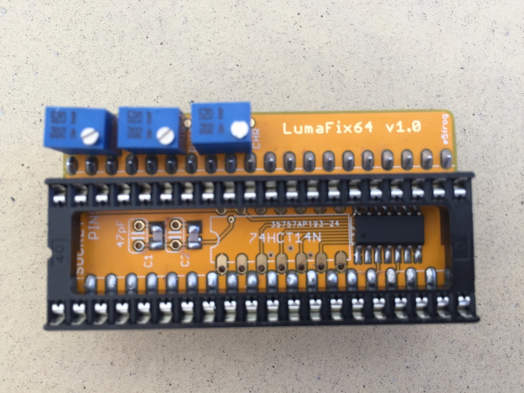
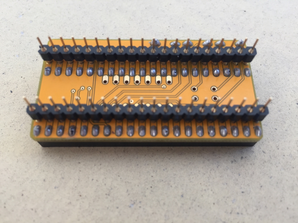
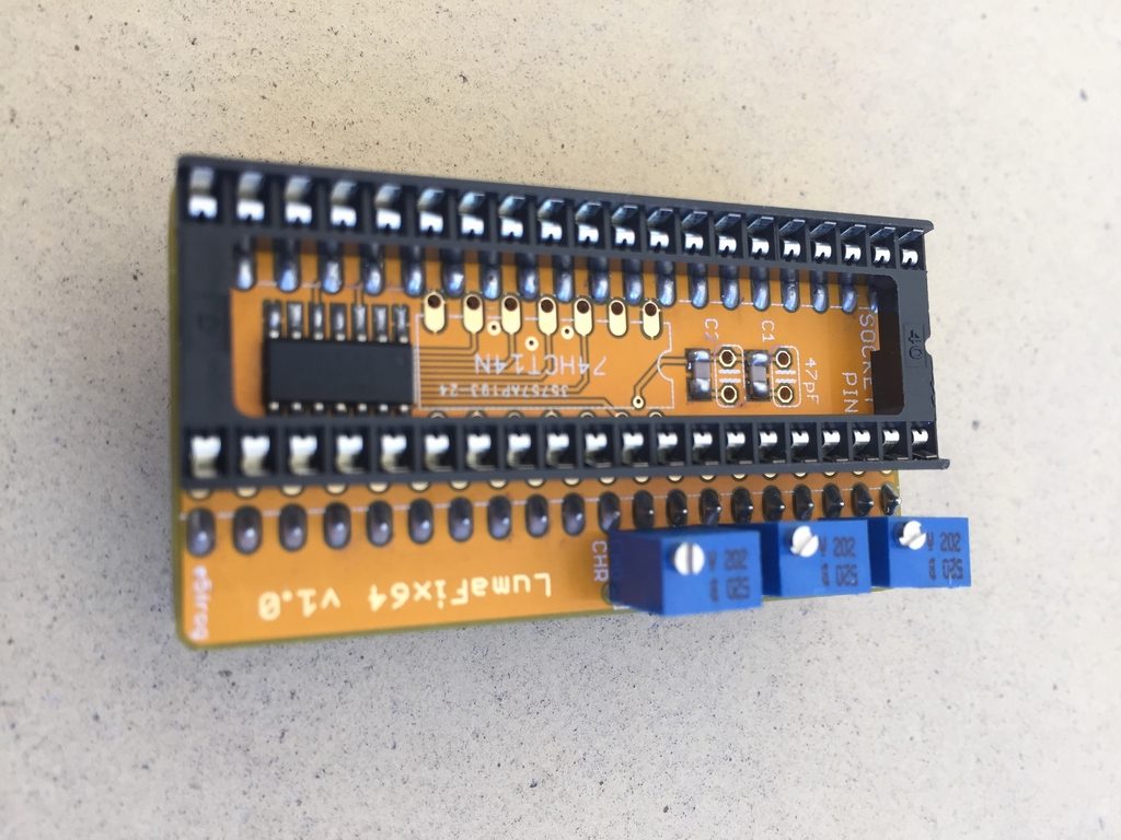
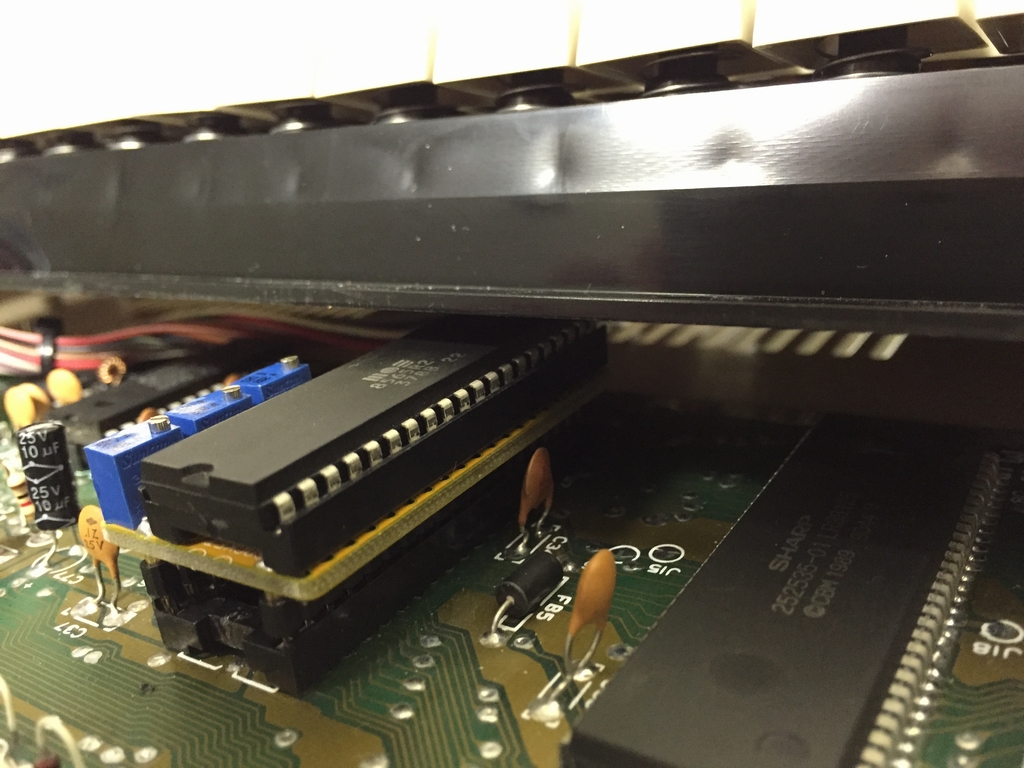
Reducing the vertical lines problem can be done by inverting the sources of the artifacts (the interfering signals) and blend them back into the picture by an adjustable amount. On a practical level, a device called LumaFix64 was created based on the combined forces of the C64 community and made available by different producers online either as a kit or as an assembled ready-to-use product. The version reviewed here was designed by e5frog and manufactured by Tim Harris of Shareware Plus. It is basically a little printed circuit board that is placed between the VIC-II graphics chip and the motherboard of the Commodore 64. It has a standard 40 pin female IC socket on top for placing the VIC-II chip in and a 40 pin male header pins on the bottom for fitting the device into the socket on the motherboard. It has small potentiometers for adjusting the AEC and PHI0 signal (vertical lines) and the Chroma signal (checkered pattern).
VIC-II Image Test Bench:
For evaluating the LumaFix64 several hardware setups and tests were applied. I used a ‘test bench’ that consisted of PAL hardware only (Commodore 64 hardware and monitors) as commenting on NTSC’s ditto would be quite an effort when living in a PAL country. However, it is expected that NTSC owners will experience similar changes in image quality when using the LumaFix64 in their equipment.
For image evaluation, a B&O (Bang & Olufsen) BeoVision MX4000 21″ CRT television was used as this little design beauty has an exceptional sound quality (and vision) and accepts both composite and S-video image signals. To evaluate the image quality on more modern hardware, a 42″ Panasonic Plasma TV (TH-42PV60EH) was used. For signal transfer, S-video and Composite cables from Retro Computer Shack were used.
Two types of motherboards were used including an old type longboard (Version A-CR, Assy no. 250407 Rev. B) and a newer type short board (Version E, Assy no. 250469 Rev. B). Both PCB’s were pretty close to being new Old Stock as no repairs have been done to either board, except for a replacement of all electrolytic capacitors and voltage regulators.

A total of seven VIC-II graphics chips were included for testing the LumaFix64. The list of IC’s for the longboard is as follows: a MOS 6569R3 (2085), MOS 6569R3 (3784), two MOS 6569R3 (4884) and a MOS 6569R5 (3786). The list of IC’s for the C64 short board is a s follows: a MOS 8565R2 (0389) and a MOS 8565R2 (3788).
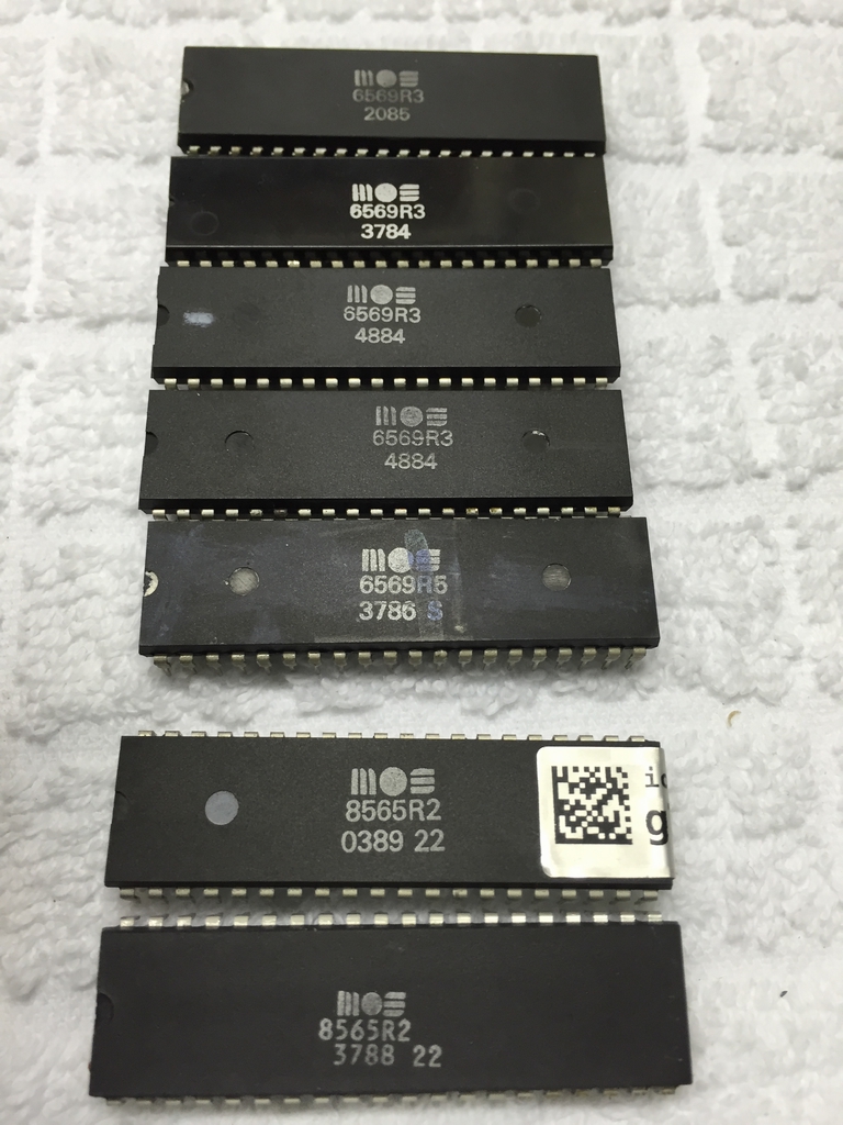
Image Quality Tests:
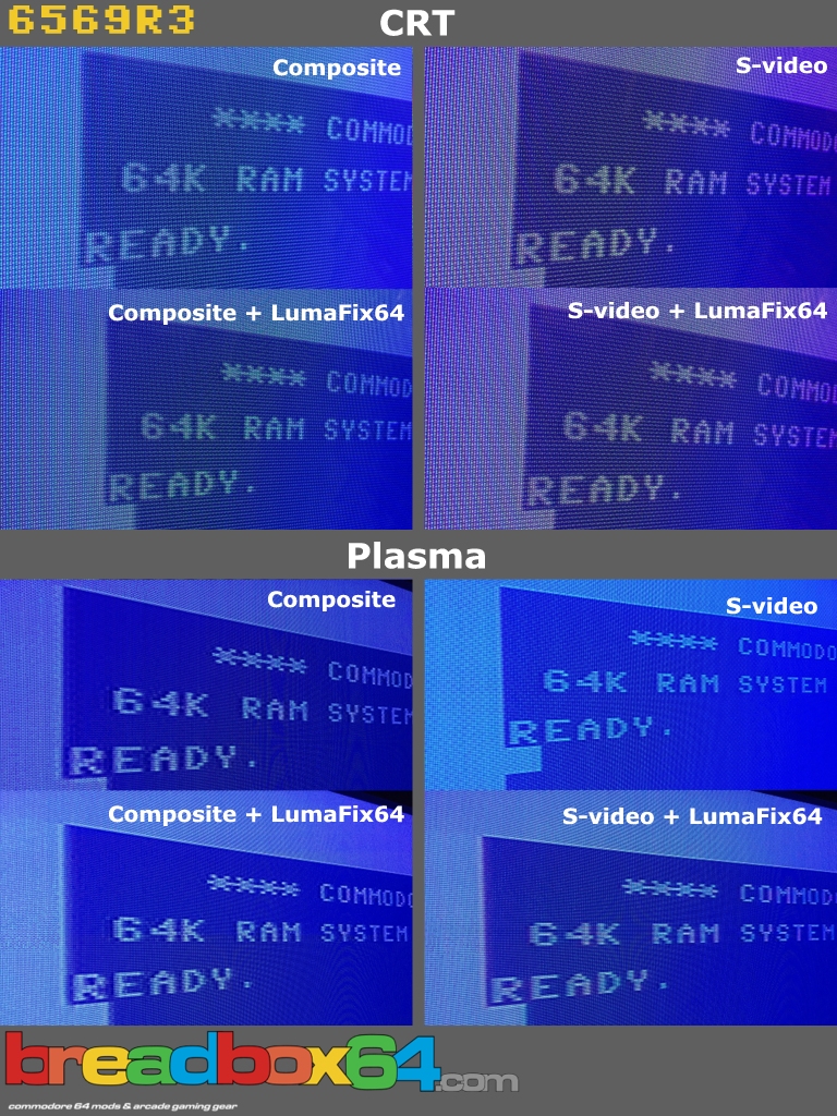
All chips were tested individually on each TV set. The image quality of each chip was initially evaluated without the LumaFix64 installed (Composite and S-video) and then with the LumaFix64 installed (Composite and S-video). To keep track of everything, screen images were taken at each step for comparison yielding a total of 56 image (8 images of each of the 7 VIC-II chips).
During the CRT TV tests, it was pretty obvious that not that many vertical lines or checkered patterns were present when using any of the chips. First I thought, that something was wrong with my copy of the LumaFix64. The biggest differences actually came when adjusting the PHI0 potentiometer. Almost nothing happened with the Chroma and the AEC pots. Obviously, the S-video video signal yielded the most crispy images. If I looked very closely, the vertical stripes were there, but not much happened when adding the LumaFix64. In general terms, no obvious differences were found among the different chips regardless of revision and motherboard used.
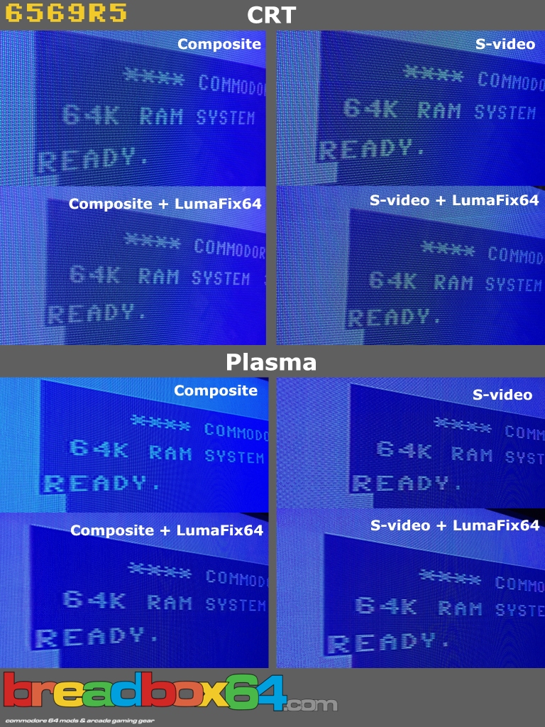
However, repeating everything on the modern plasma TV, everything changed! The images were downright horrible and the LumaFix64 wasn’t broke after all! Without the LumaFix64, the Composite images contained profound ghosting artifacts, blurry edges, vertical lines and everything looked smeared while the S-video suffered from severe checkered patterns but the images were a little sharper. Using the Lumafix64, the Composite signal could be bettered but I never managed to remove the artifacts entirely. The S-video signal could also be cleaned up but at the cost of image sharpness. On the positive side, images produced by the MOS 6569R5 graphics chip left the rest of the test chips in the dust! This chip showed far less vertical stripes, less smearing and checkered patterns. In combination with the LumaFix64, I managed to achieve a pretty good image on the plasma TV. To be honest, if I should use a modern TV for any of my Commodore 64 needs, this would be the only chip I would consider using. The rest of the tested chips were simply not worth using!
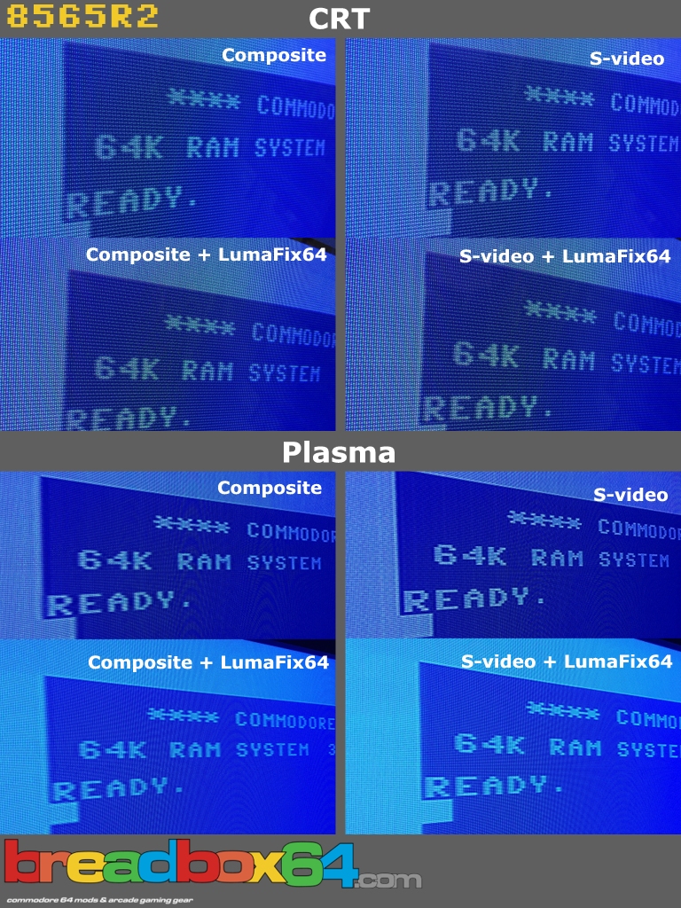
Here are the before and after photos of three of the chips (6569R3, 6569R5 and 8565R2). The images are very forgiving and some of them look a lot worse in real life. The one that needed the LumaFix64 the most is the 6569R3 in my opinion (The differences in color of the Plasma/CRT images are caused by my camera and not the LumaFix64).
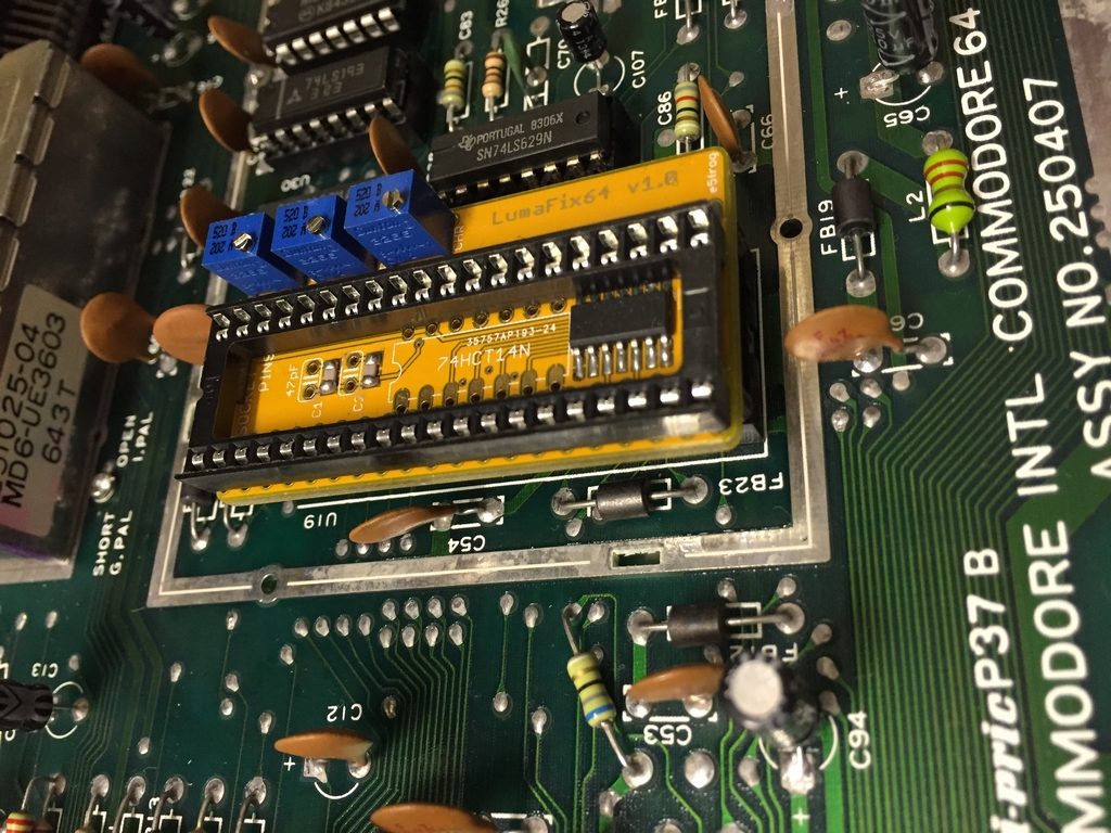
Fitting the LumaFix64 into the Commodore 64:
The device adds to the overall height of the graphics chip. No problems arose when using the device inside a breadbox case. Fitting the LumaFix64 in the narrower Commodore 64C case is tight, but should be possible without any modifications. However, if the soldering iron is hot and the urge to mod is present, removing the VIC-II socket on the motherboard and soldering in an ultra low profile socket could be done to reduce the overall height. But it should not be necessary for the average user who just wants better images.
Final Thoughts:
Don’t expect the LumaFix64 to remove any of the image artifacts completely and give you an emulator-perfect image (who wants that anyways…). What it will do, is reduce the main reasons that causes the vertical stripes and checkered patterns. I always use the B&O television for my Commodore 64’s as it has a great image and the sound is fantastic. On this TV set, the LumaFix64 may improve things a tiny bit, but not to an extent that I would go through the hassle and install LumaFix64’s in any of my current machines. Somehow this TV manages to compensate for the differences in signal from the Commodore 64 regardless of VIC-II graphics chip being used. However, using a modern day TV the LumaFix64 is the only way to get an acceptable image quality. Without it, both types of video signals (S-video & Composite) are horrible. The plasma screen that was used is pretty forgiving when it comes to analog signals and it only has 720 lines available. Using TV’s with even higher resolutions, the images are expected to worsen. Thus, getting the best image quality on a modern TV, the combined use of a MOS 6569R5 graphics chip and the LumaFix64 should get the highest attainable image quality.
Even better image qualities can be achieved if a RF modulator mod is carried out. However, this kind of modification removes some of the soul from the Commodore 64 in my opinion. It may also cause other problems as the mod is not trivial and includes quite a bit of soldering, as well as knowledge and technical skills. Thus, for an easy image fix, the LumaFix64 is the smooth path to better images on your retro hardware.
Just a final thought: If you own more than just a few C64’s, always use a modern TV and consider installing LumaFix64’s in all of them, maybe getting a truly design beauty, like the B&O BeoVision MX4000, could be the way to go. I payed like 50 $ for mine and the design of that TV never goes out of style!
NOTE: This article has also been been published in Europe’s #1 C64 scene disk magazine – Attitude #17 by TRIAD (link).
© breadbox64.com 2016
Does this affect the picture on the old RF lead that you tune into a channel? I got a flat screen tv that the C64 tunes into and works okay but would this improve the picture, do you know?
I would expect an improvement in the RF signal from the modulator box with a LumaFix64 installed. However, if you really want to improve on things I would use the S-Video output instead. Get a quality cable on Ebay, add a LumaFix64 and you will get the best signal possible 🙂
Looks great, I just finished the second prototype of LumaFix128 – seems it’s needed. Also made a really low LumaFix64C, not that it seemed very popular though.
Do you think there will ever be a 128 version for this? This vertical banding is particularly noticeable on my C128D. Granted, in a perfect world the fix for the 128 would apply to the 64 mode, too. One can dream… 🙂
It seems that some people have been trying to convince e5frog to make a C128 version of the LumaFix as well. I’m not sure how it is going as the thread is more than a year old… You can find the thread here (link)
Do you know if it is compatible with the 6572 VIC2 for PAL N?
Hi Marcelo, I honestly don’t know – sorry 🙁 If I was you, I would contact e5frog from lemon64.com and ask him as he has designed the LumaFix64. Tim Harris from Shareware Plus has produced the version I have and he may also know wheter or not the LumaFix64 works on Drean C64’s. Please report back if you find the answer as other South American users may be interested in the LumaFix64. Thanks 🙂
Test to write in red or green on blue. This looks horrible on some (most?) 8565 VICs. There is a checkered pattern, a noise, it looks like dithering was applied when it wasn’t. This is even visible on CRTs! LumaFix can fix this with its Chroma control. So here we have a good use for LumaFix even when using a CRT display.
I was wondering if there would be any downsides to placing the VIC onto a separate board at the location of the RF modulator using a flat-cable (DIP-to-pin). I want to make a custom Lumafix/RF-modulator board and this would also leave more room for a heatsink.
Would the signals degrade too much or get interference you think?
Hi Evert, sounds like a very nice project. That would certainly solve the fitting issue when using the Lumafix64 in a slim case 🙂 Whether or not that will introduce more noise into the video signal is a really good question. You may just have to try it out…
I have tried it on 8565R2 c64c and found that the lumafix64 did not work and picture was much worse than just having composite video going directly to a modern lcd tv.