
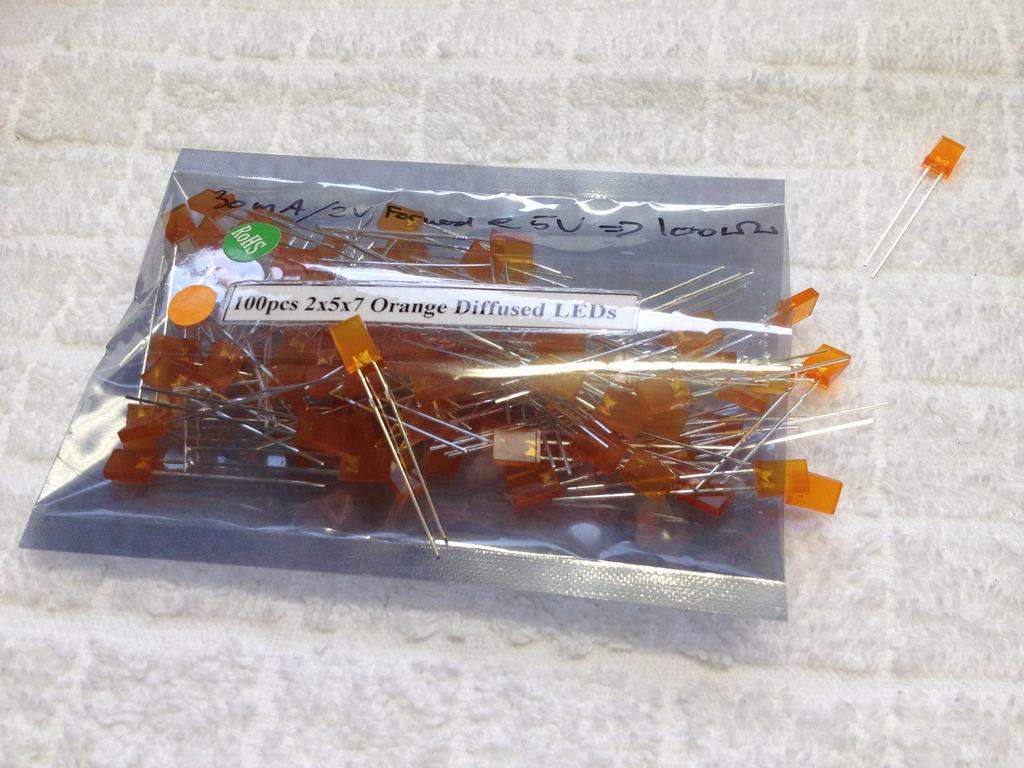
I recently recieved two cases from the Kickstarter campaign for my C64 Reloaded boards. A transparent and a blue one. The blue case will eventually get orange function keys whenever Phase 5 from the Indigogo Campaign have made the new key caps. So I wanted to mod the case with an orange LED instead of the standard red one. I got 100 orange LEDs from China on Ebay for 4.50 $. A 100 Ω 1% resistor was soldered to the plus side of the LED and the other end of the lead went to the plus side of the plug that goes onto the pcb for the 5V source.
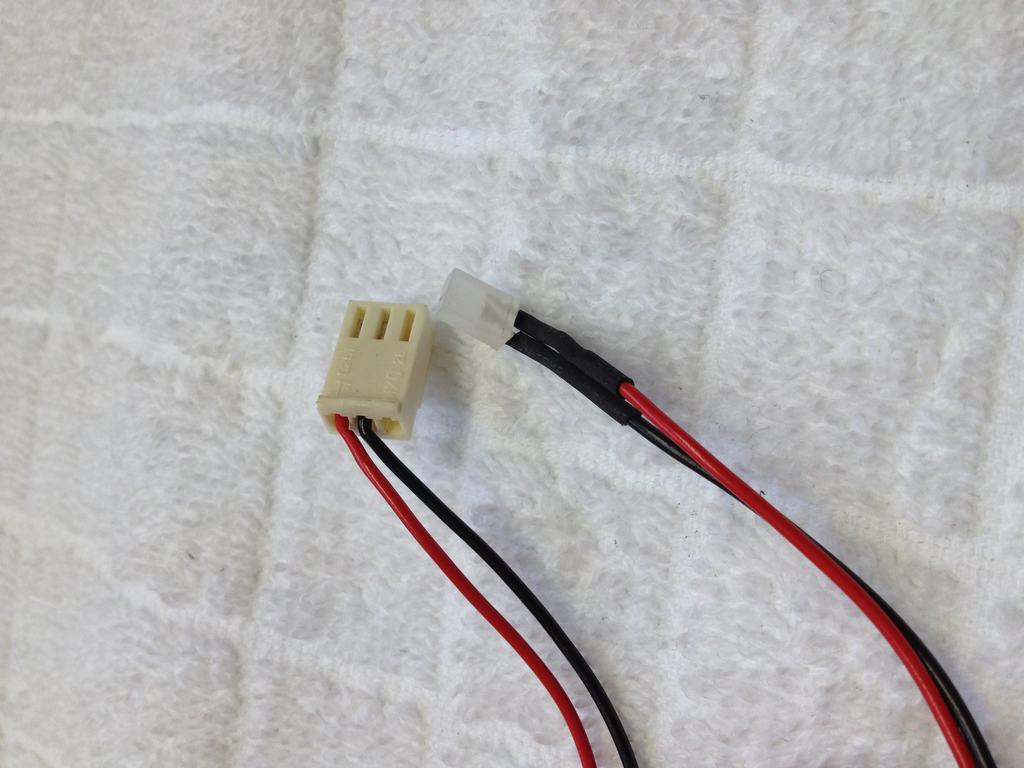
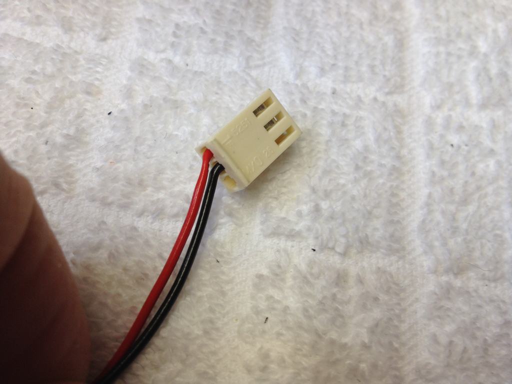
This is how the original LED and plug looks like – but it was red and ugly for my new case…
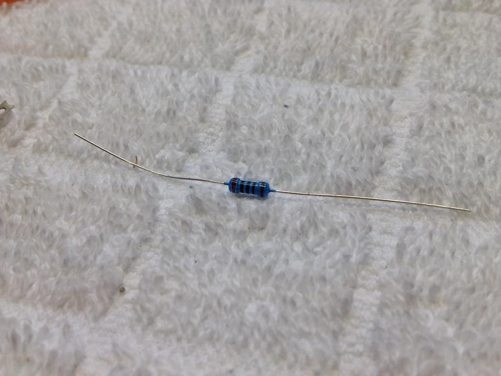
All the stuff needed for the mod: A 100 Ω 1% resistor, a small 3 pin female plug, some heat shrink, a gas burner and an orange square LED (2 x 5 x 7 mm in size).


The lead was then crimped into the female part of the plug using an orange wire – when you mod, why not make it look cool on the inside as well…
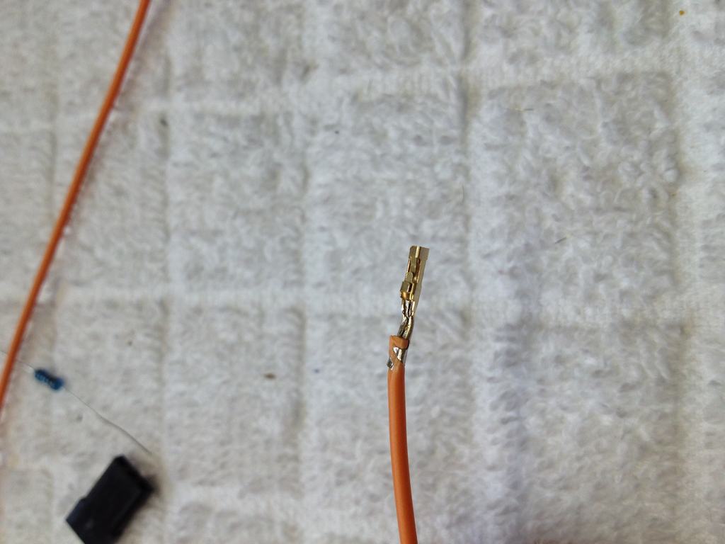
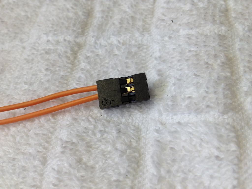
The female connector assembled and ready for installation into the C64 reloaded board in comparison to the original lead showing the plus and minus side of the connection.
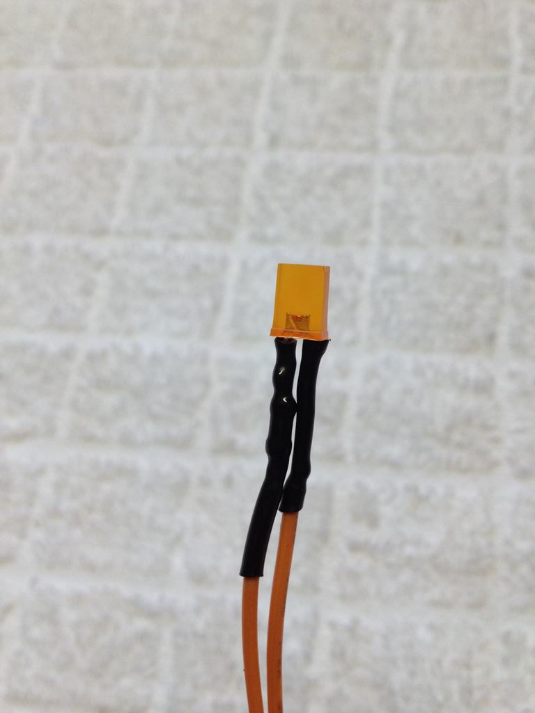
The square LED with the resistor in shrink wrap.
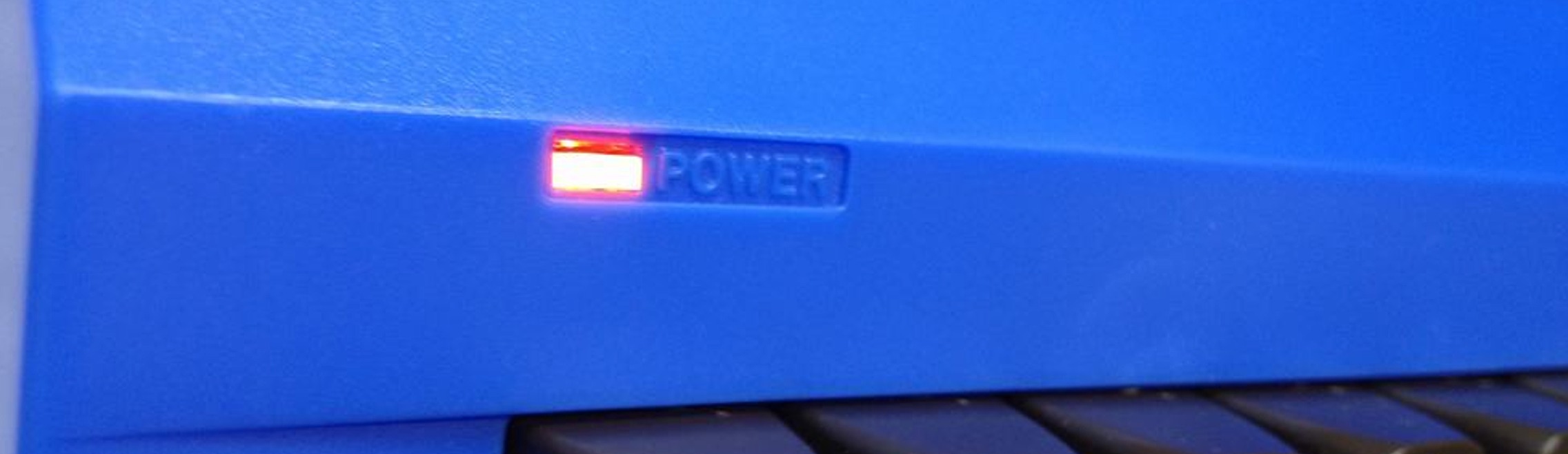
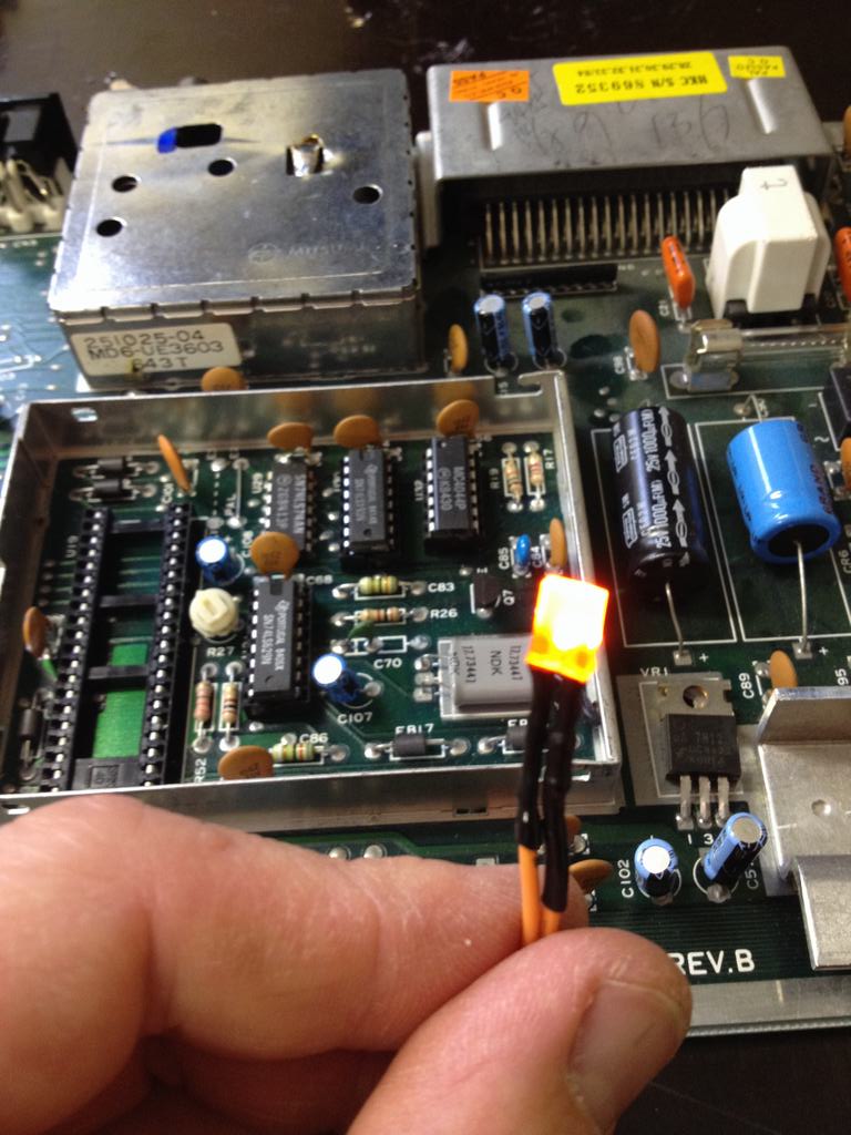
This is what my efforts looked like when powered on. Success! I always have a spare board for fooling around with. I’d rather burn an old repairable Commodore 64 PCB than a newly made C64 Reloaded…
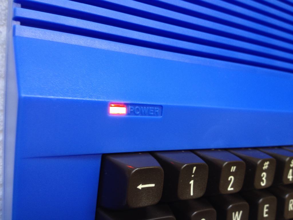
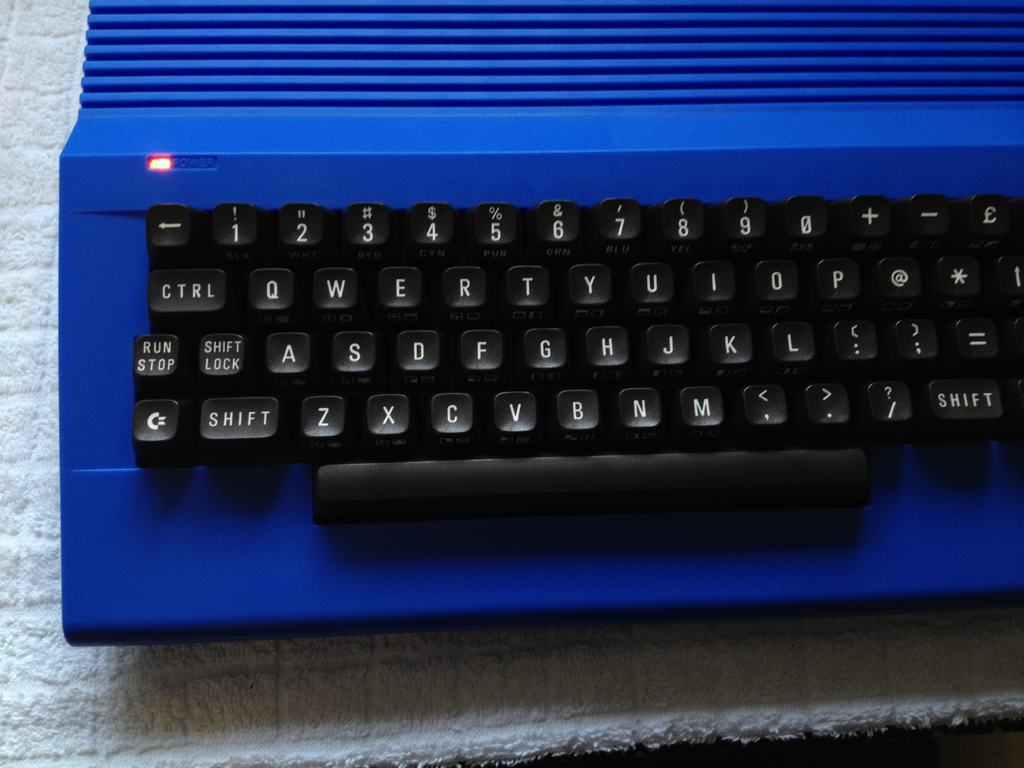
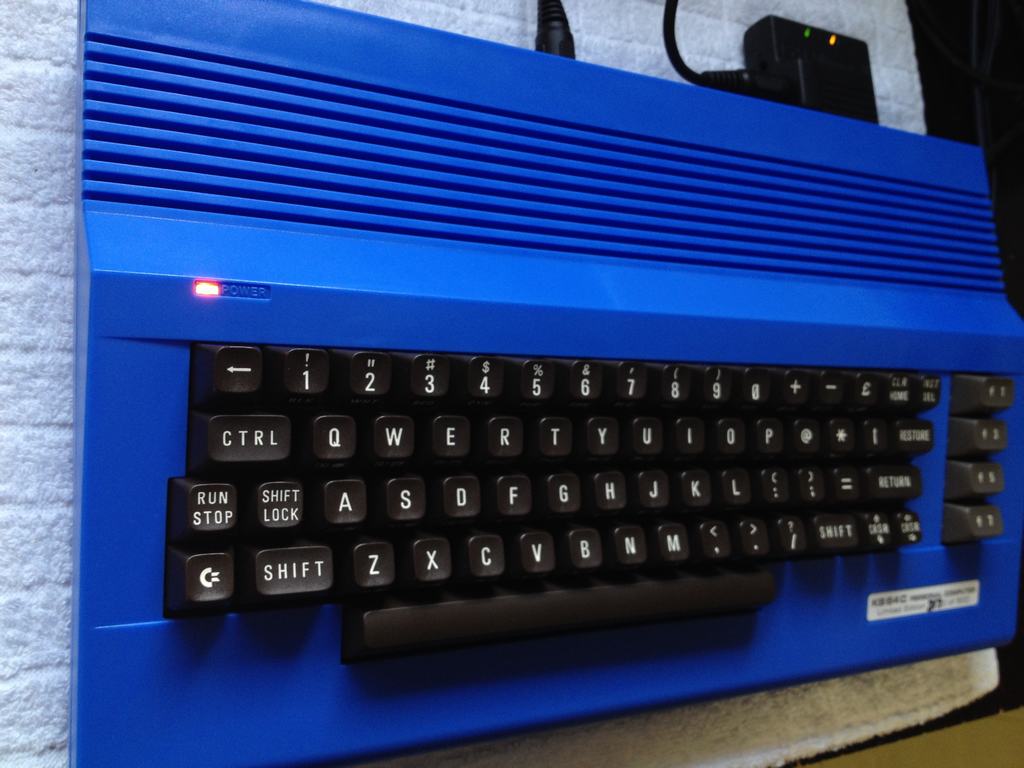
And the final look in the blue Kickstarter case… Now I’m waiting for the new keys to show up from Phase 5!
© breadbox64.com 2015
Hi!
Great blog, I am building a similar machine (C64C Transparent Case and C64 Reloaded) and I purchased a ready-made blue LED and cable for C64 but I wondered what the 100 Ω 1% resistor was used for? To permanantly dim the output brightness of the LED? Or for other saftey / power reasons?
Thanks for any help!
Hi there and thanks!
The LED that I use in the post has a voltage drop of 1.8-2.2V across it (forward voltage, Vf). The LED power source on C64 motherboards (including the C64 Reloaded) runs at 5V. The current that the LED needs to be reasonable bright is 30mA (forward current). In order to limit the current going through the LED I added the resistor based on Ohm’s Law using a forward voltage of 2V (U/I=R -> (5V-2V)/0.030A = 100Ω).
Adding a resistor will permanently dim the brightness of the LED. If no resistor is added, the lifespan of the LED will most likely be reduced as the LED will eat the current until it basically melts. However, I would not expect a missing resistor to do any harm to the motherboard, the LED would just be really bright and then after a while stop working.