
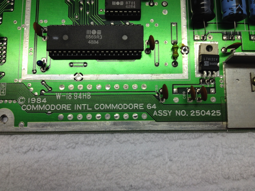
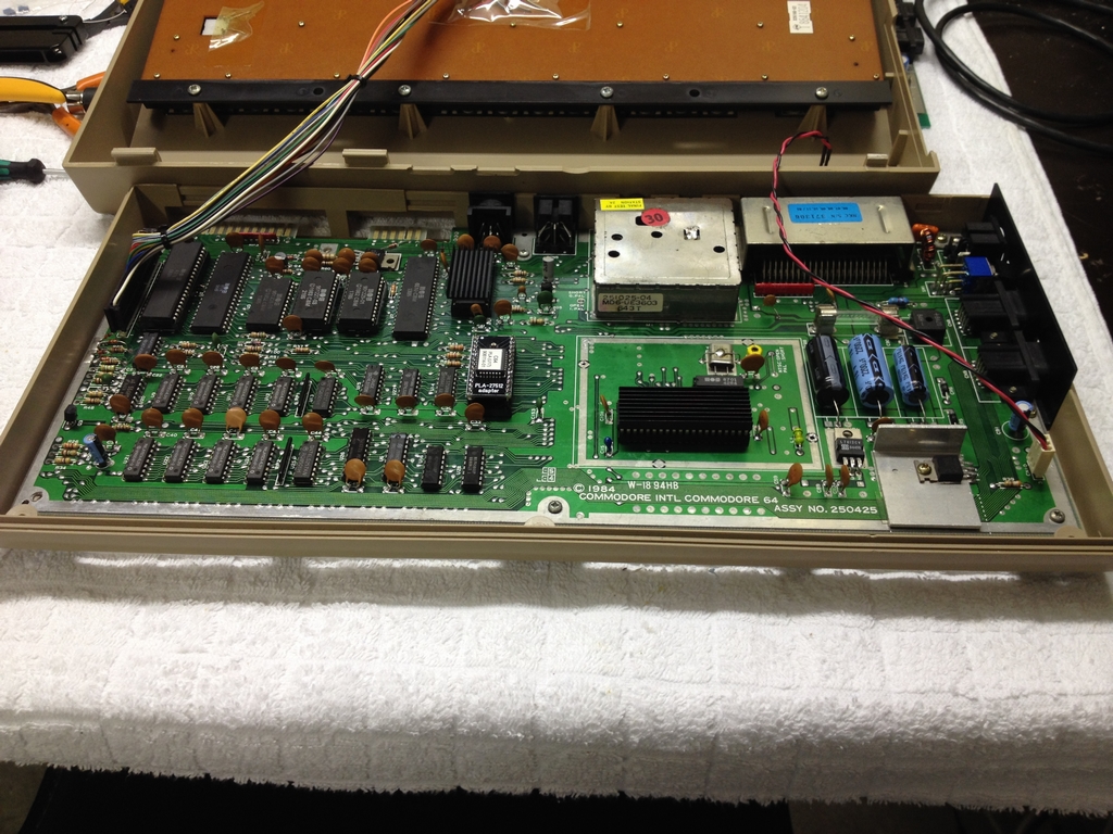
This machine is an Assy No. 250425 long board.
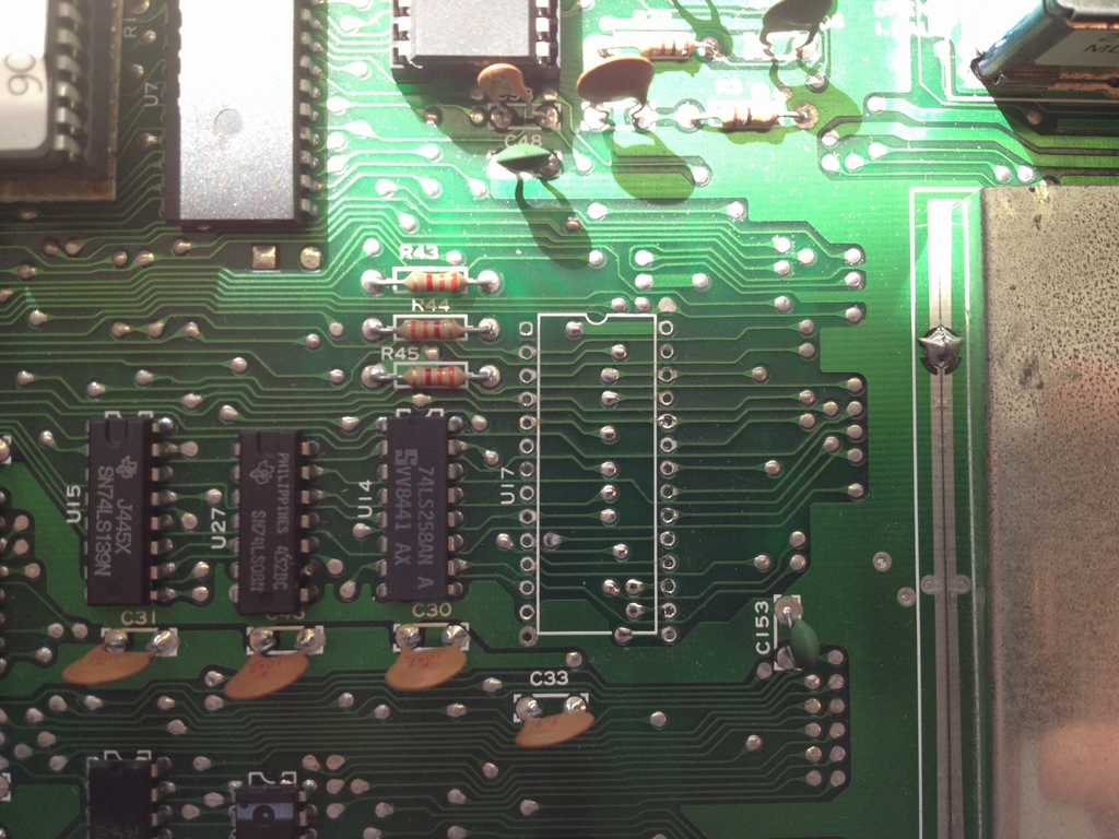
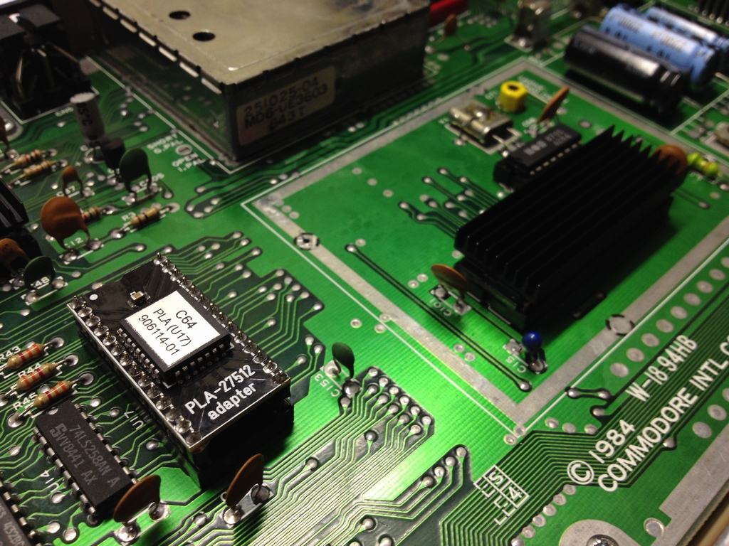
At startup, the machine had a completely black screen. So I swapped the PLA with a fresh new one as this usually cures the black screen. I also swapped the VIC-II with a known working one to rule that one out as well.
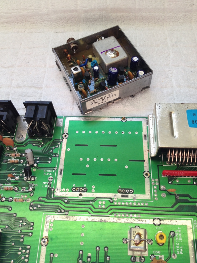
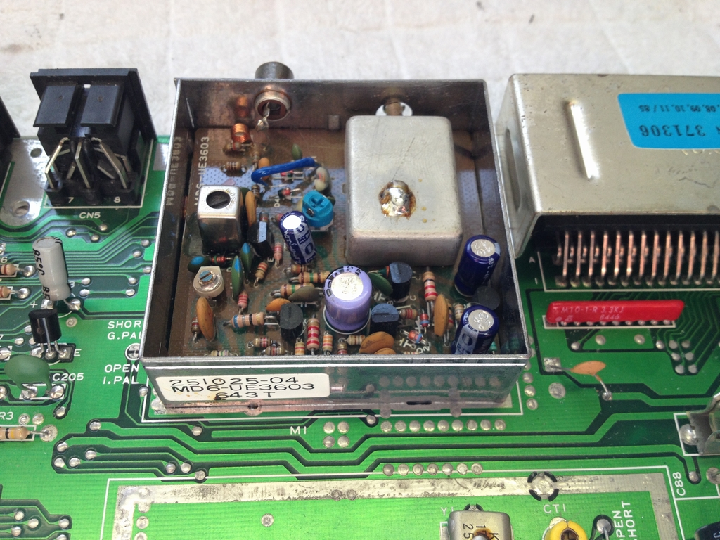
That did not cure the black screen either. Bummer! I don’t know why I decided to the following and in retrospect it surely was not the brightest thing to do either… But it was 2.30 in the morning and the soldering iron was hot and I had this strange feeling that the RF box was causing the problem. So I swapped the entire RF box and replaced it with a known good one.
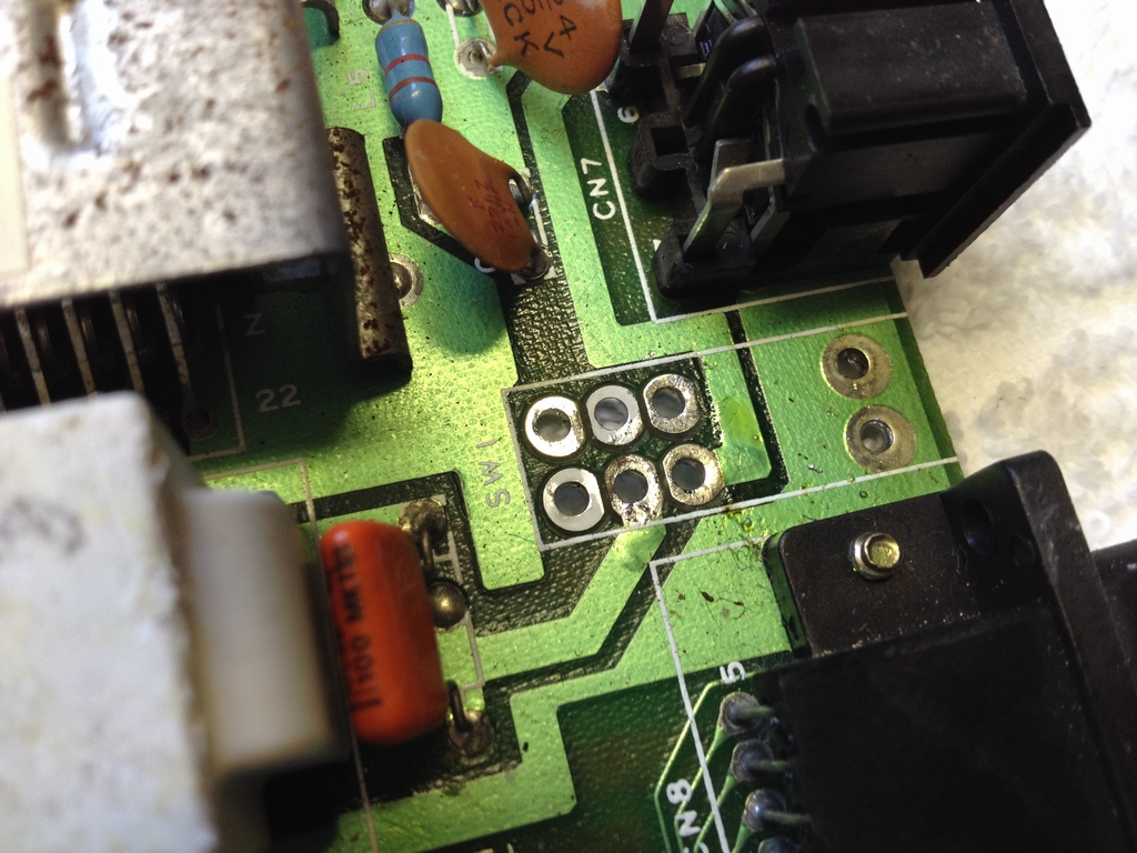
Well, the black screen was still there… I left the board and returned a couple of days later to give it another go. I then started from the power source and discovered that the power LED was not lighting when powering up the board. How the heck could I have missed that – Rookie mistake #1? Anyways, now I had something to work on. I tested the power supply and it was giving me all the correct voltages. I then used my multimeter to see if the board got any voltages using the solder points on the back of the board:

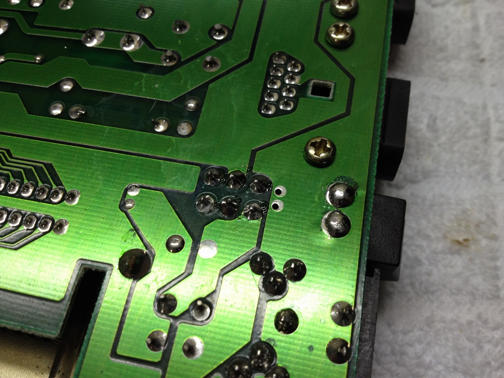
No 5V was going into the board! I therefore suspected the power switch to be the cause as I have read somewhere that the contacts will corrode over time and I knew that this particulat board had spent like 20 years in the attic of an old barn. So I swapped the power switch for a spare one:
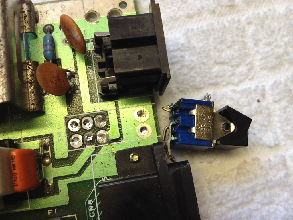
Cleaned the holes with a vacuum pump and some solder braid and in with a good one.
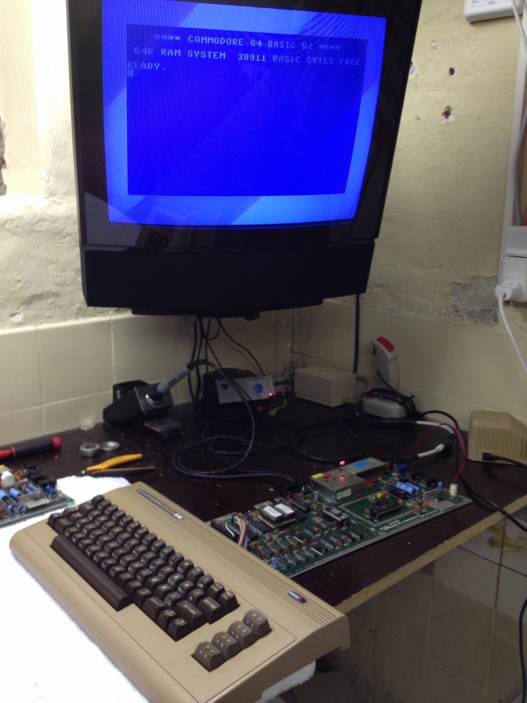
The board was now getting 5V and the Commodore 64 Basic blue screen was greeting me. Wuhu!
So I guess replacing the PLA and the RF-box was a waste of time (and money!). The board had a special character set (Danish) that the friend I was fixing the machine for did not want to keep. So I soldered in a couple of sockets and replaced the Kernal and the Character set with standard versions.

For the final testing I put in my 64 Doctor Diagnostic Computer Test cartridge.

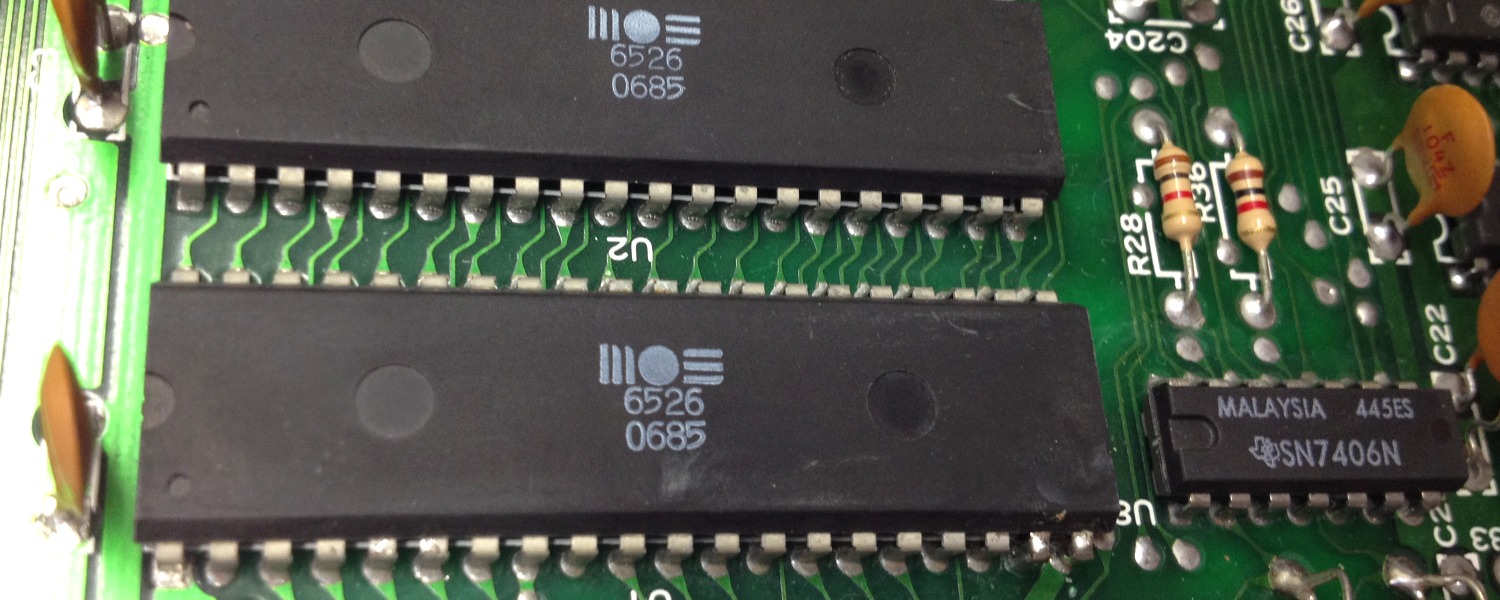
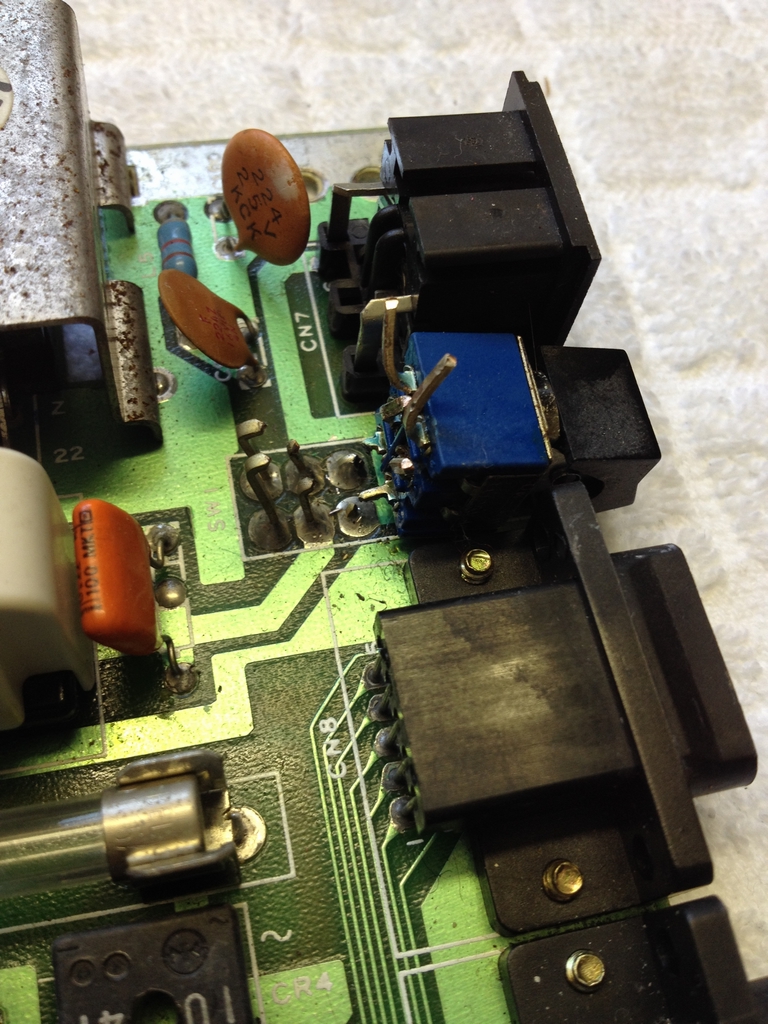
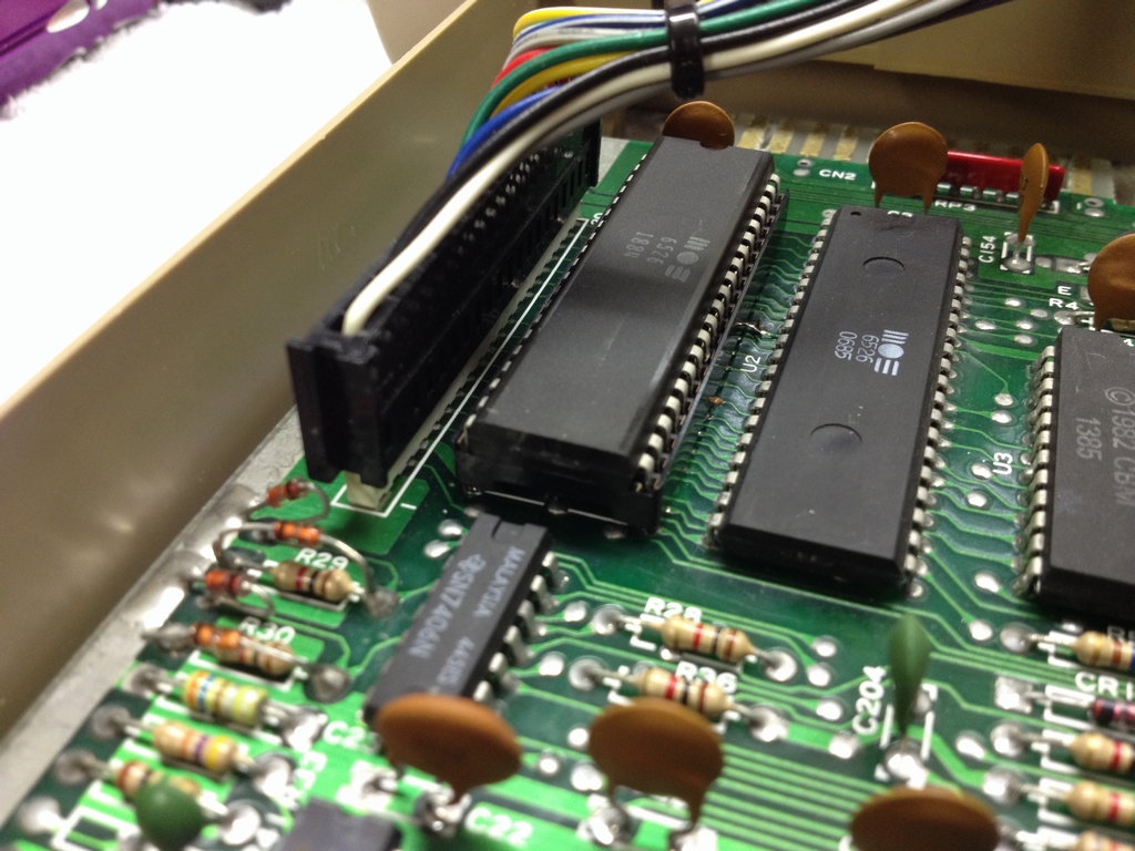
Everything worked except for the ‘Up’ direction of the joystick in Port 2. This is controlled by the CIA chip at U1 (MOS 6526). I therefore tracked the ‘Up’ connection from the joystick port and all the way back to the CIA chip at U1 at the other end of the board. As I could not find any broken traces, I figured that the CIA chip was broken and removed the faulty chip.
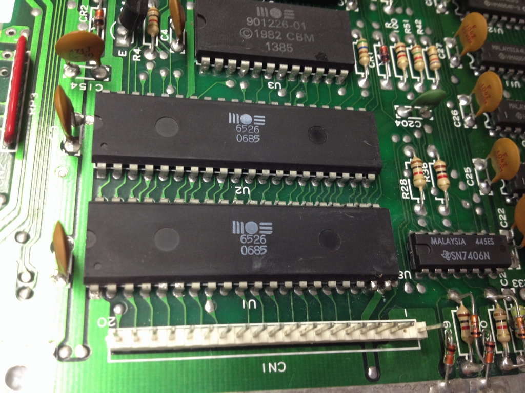
Unfortunately, I also removed a copper trace at the buttom left corner. No biggie as a piece of wire could easily be fitted before soldering in a new socket which would hold the new CIA chip.


With the faulty CIA chip replaced the ‘Up’ direction also worked. Another breadbox fixed and ready to do some gaming!
© breadbox64.com 2015