

A year has passed since Mod of the Year 2015 was presented on these pages (link). That mod was based on a very discolored breadbox case which was spray-painted. It also had heaps of holes to accommodate potentiometers and plugs for the audio signals. As this years mod, Mod of the Year 2016 uses a beautiful transparent case, a lot of effort has been put into preserving the case and none of the mods required drilling holes into it. The transparent case is also a neat way to show off the internals of the machine (why go through all the trouble of modding it if it cannot be seen, right?). The entire Mod of the year 2016 mod is a compilation of several previously described mods as well as a few new ones. I’ve worked on the machine for quite some time and this is the complete list of what has been done to it.
Case Mod
Power LED Mod
3D Printed Keyboard Mounts
Flashing Dashing C64 Mod
Power Switch Mod
RF Modulator Mod
ZIF Socket Mod
Capacitor Mod
Switchless Kernal Mod
SD2IEC Mod
Switchless Reset Display Mod
New Keycaps
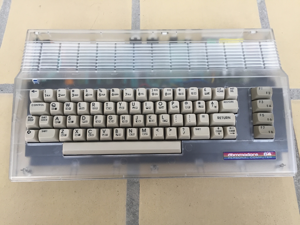
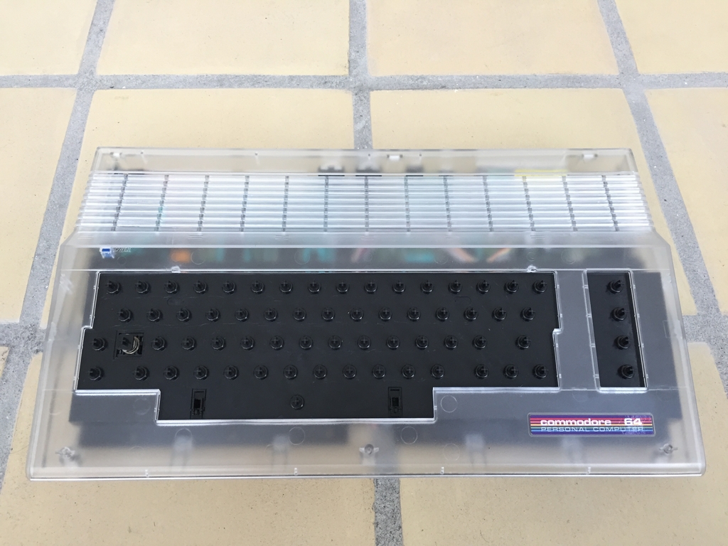
Case Mod
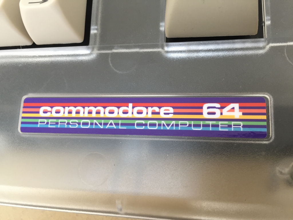
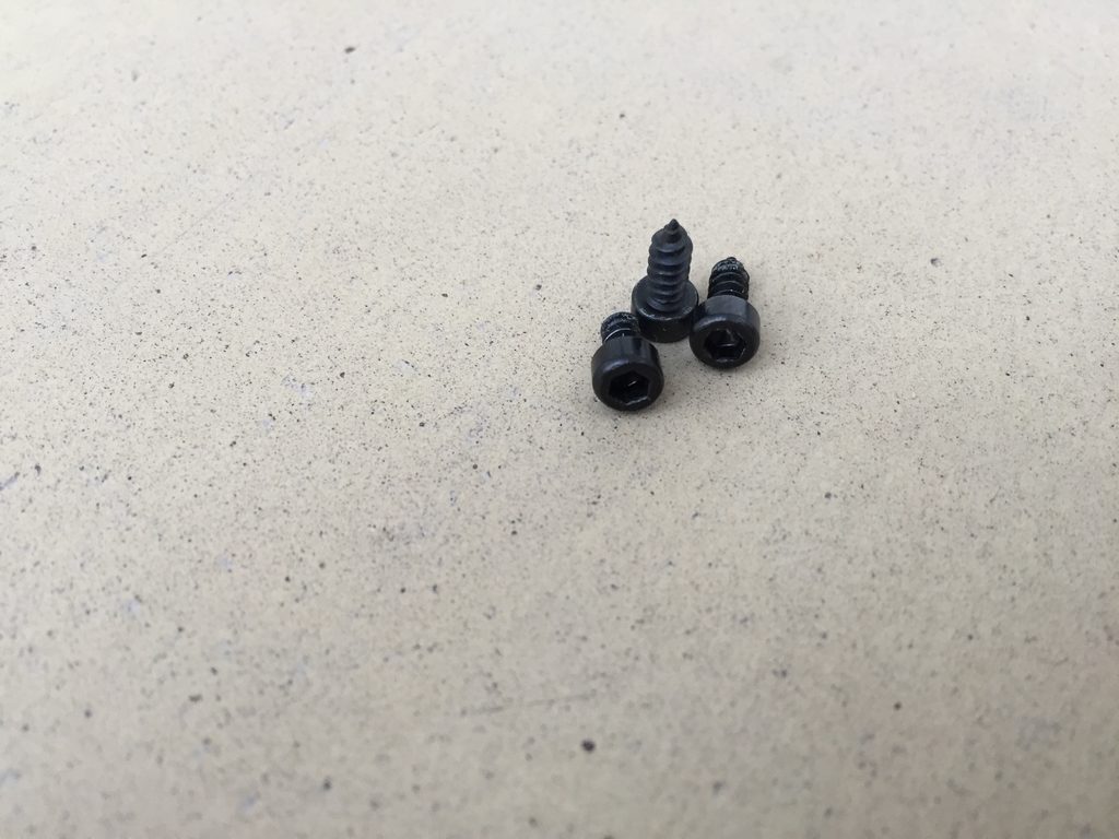
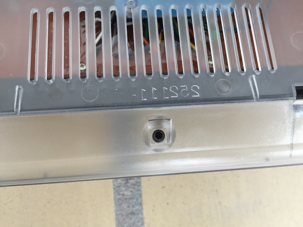
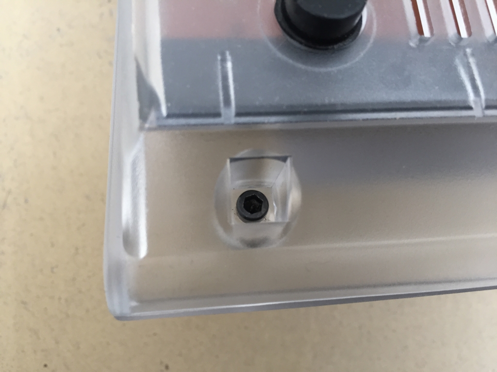
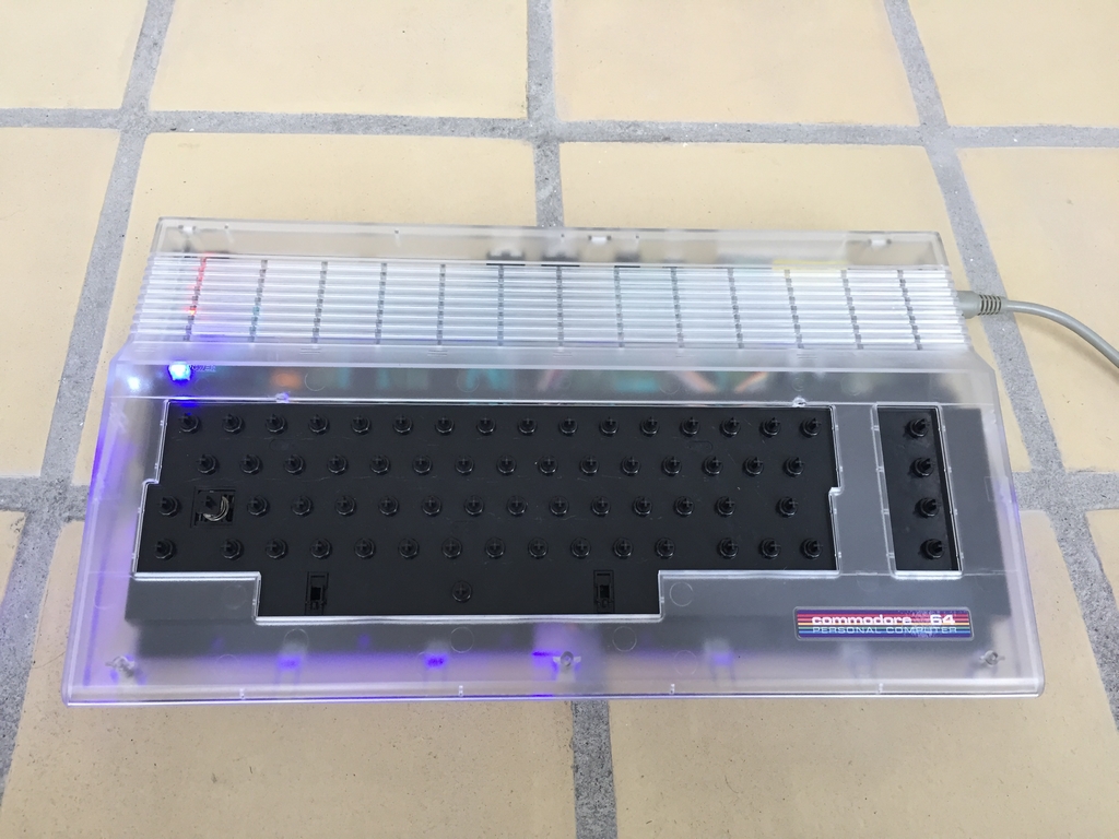
All the electronics have been placed in a transparent Kickstarter case (link) with a Commodore 64C short board (Assy 250469 Rev. 4). The keyboard is just a standard white/beige Commodore 64C as I’m still waiting for new colored keycaps from Phase5. Can’t say I’m very impressed with how they keep postponing the delivery date! Insted of using the standard Kickstarter case sticker, I got a more colorful one from RunStopRestore (link). The standard metal colored case screws were exchanged with these black self-tapping ones from Ebay. Just adding a little detail!

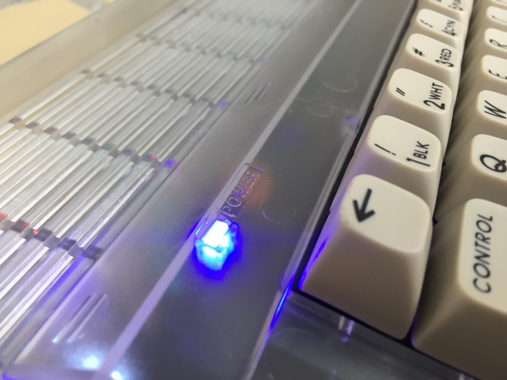
Power LED Mod
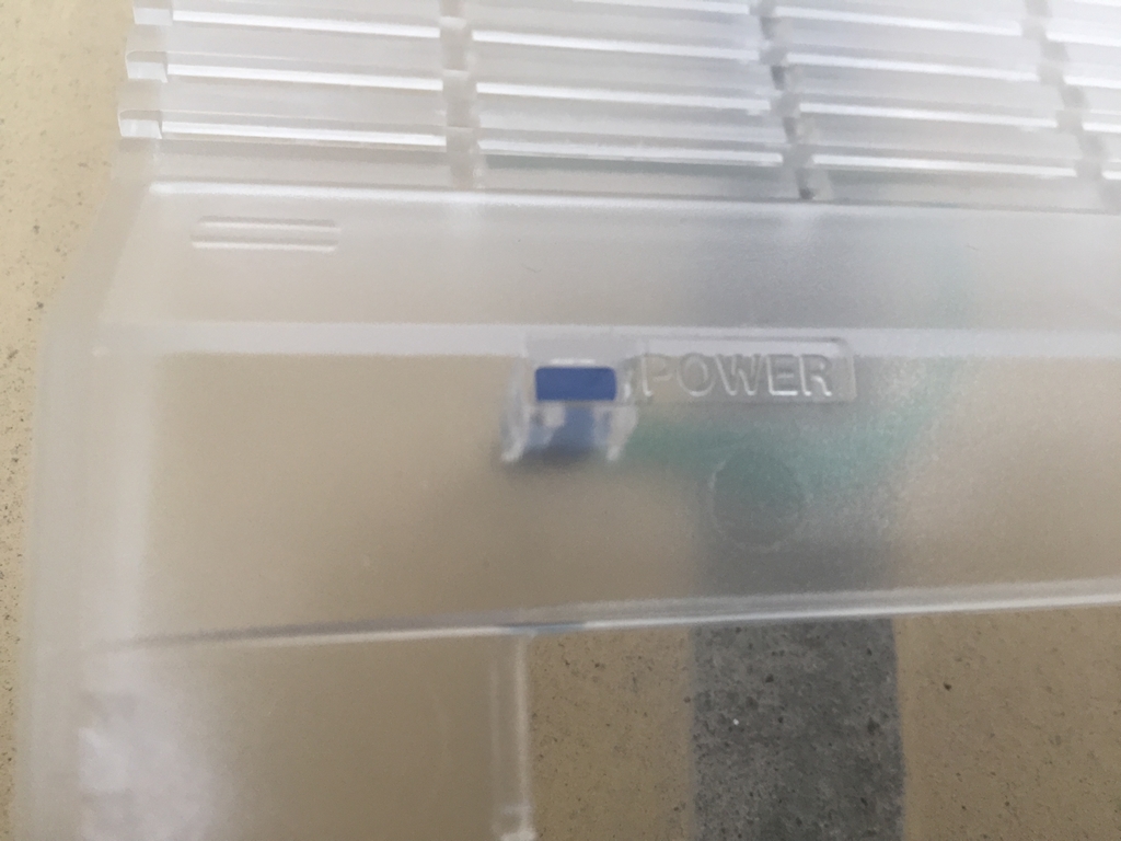
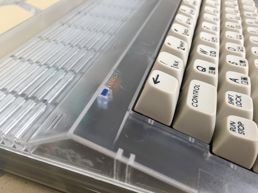
The plan is to use some transparent blue colored keycaps, so a blue power LED was made as described here (link).
3D Printed Keyboard Mounts
The 3D printed keyboard mounts look a little nicer in the transparent case than the stock metal ones… The mounts can be seen in further detail here (link).
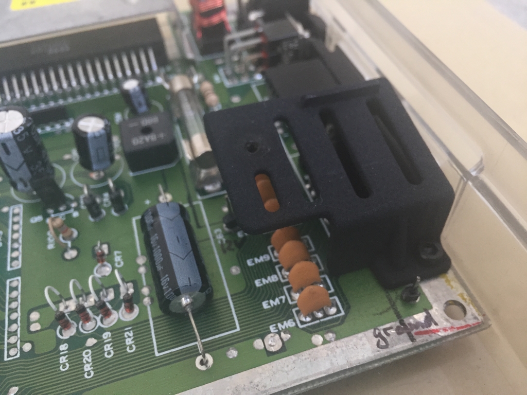
Flashing Dashing C64 Mod
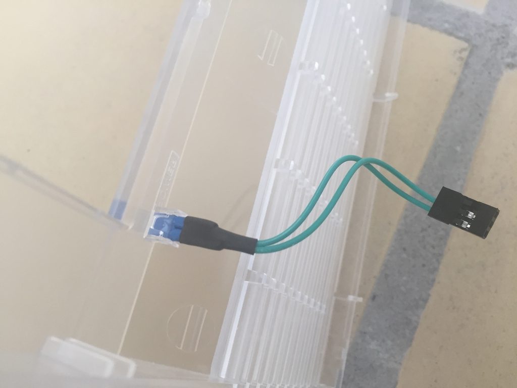
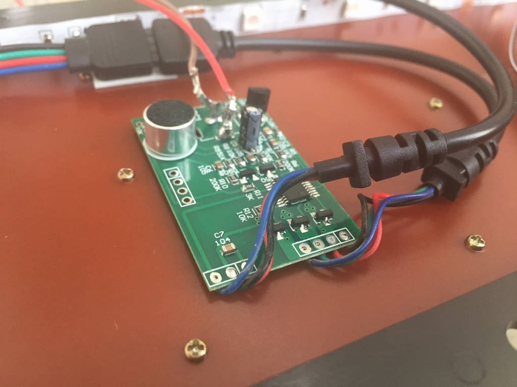
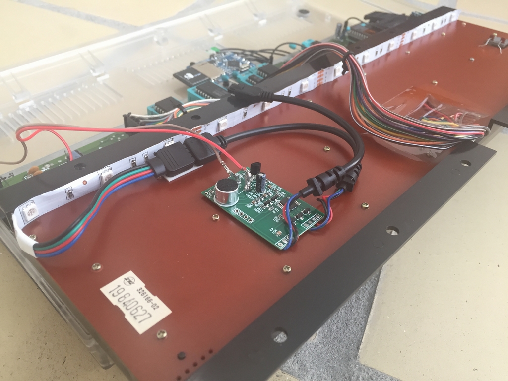
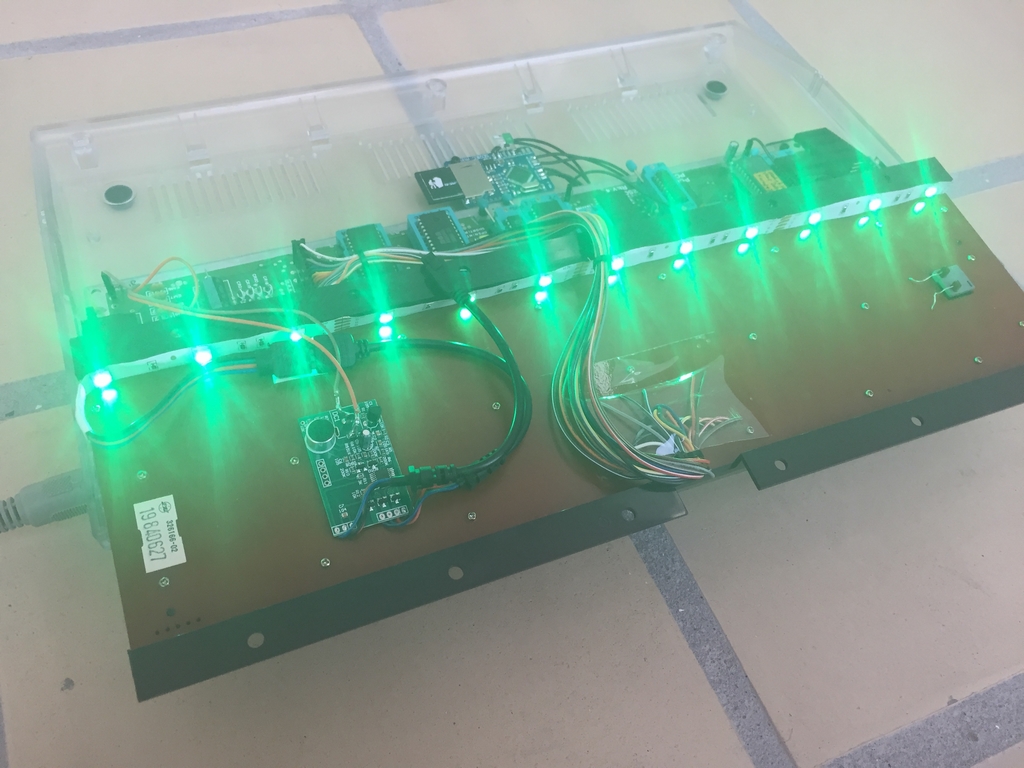
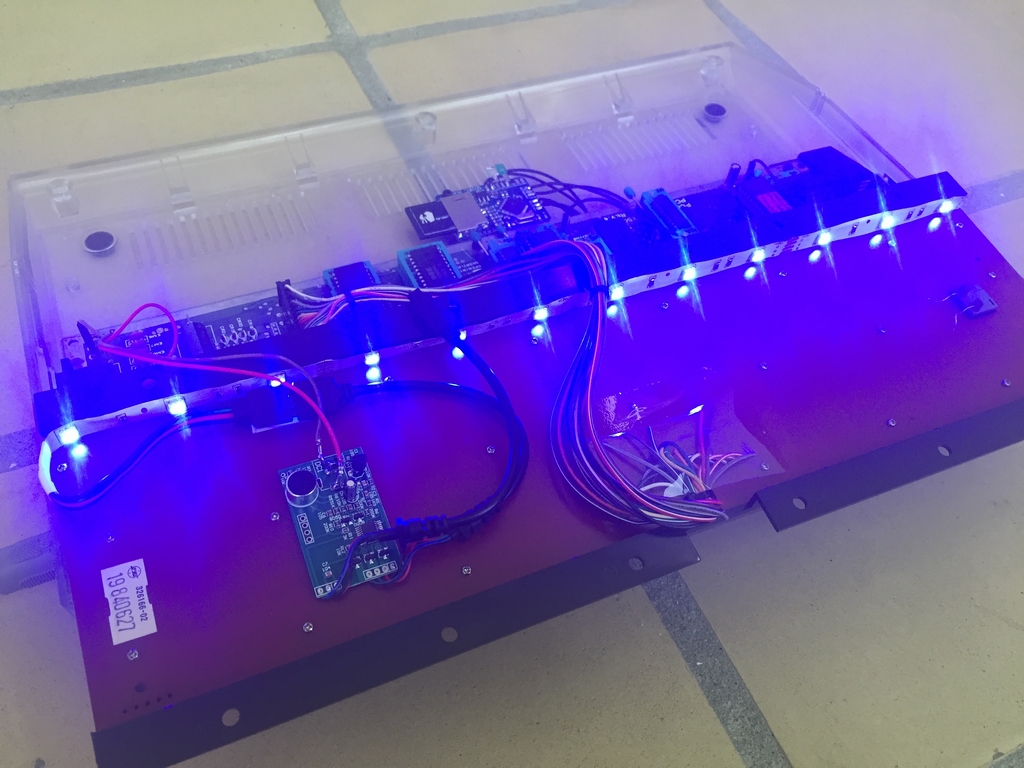
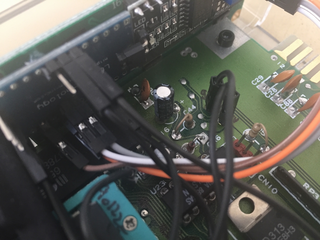
To put some color into the machine, a RGB LED strip was mounted under the keyboard as described here (link). The case of the control unit was removed to make it fit inside the COmmodore 64 C case. The power plug was replaced by two cables to grab 12V and Ground directly from the motherboard.
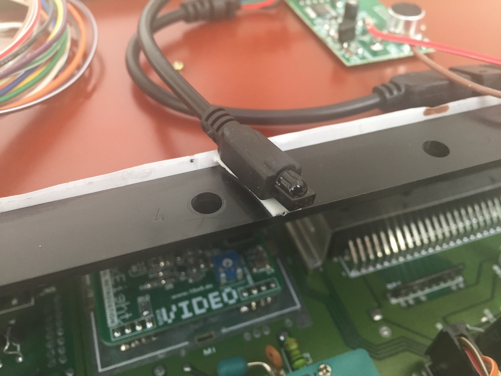
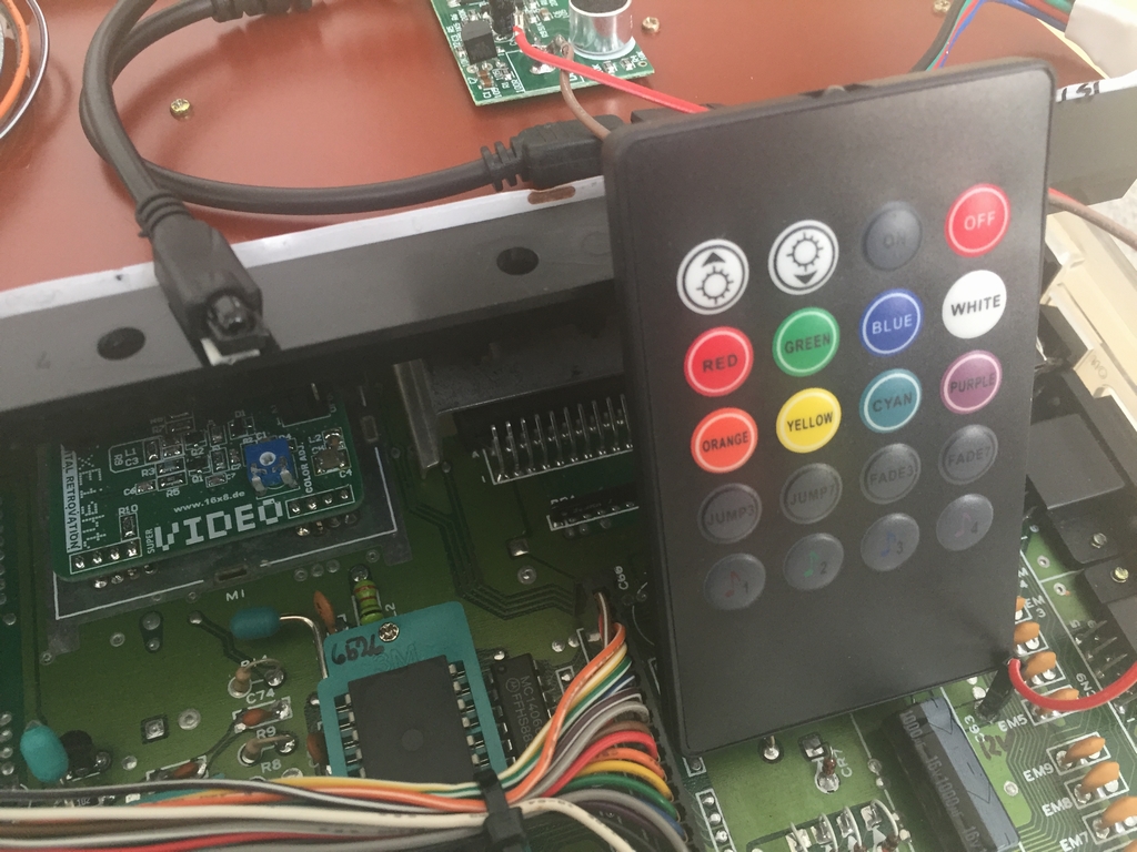
The unit comes with a remote control and a small receiver. Placing the receiver part on top of the anterior part of the keyboard makes it possible to change options without taking the case apart.
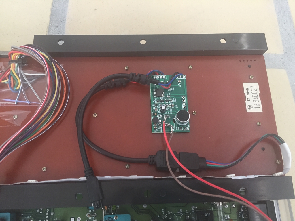
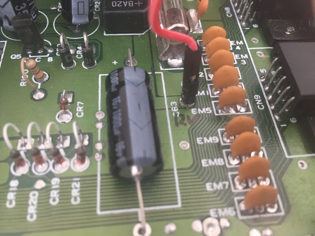
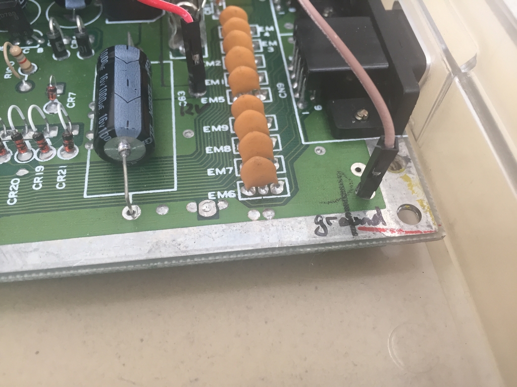
These are the 12V and Ground spots to power the device.
The RGB LED mod can show pretty much all colors…
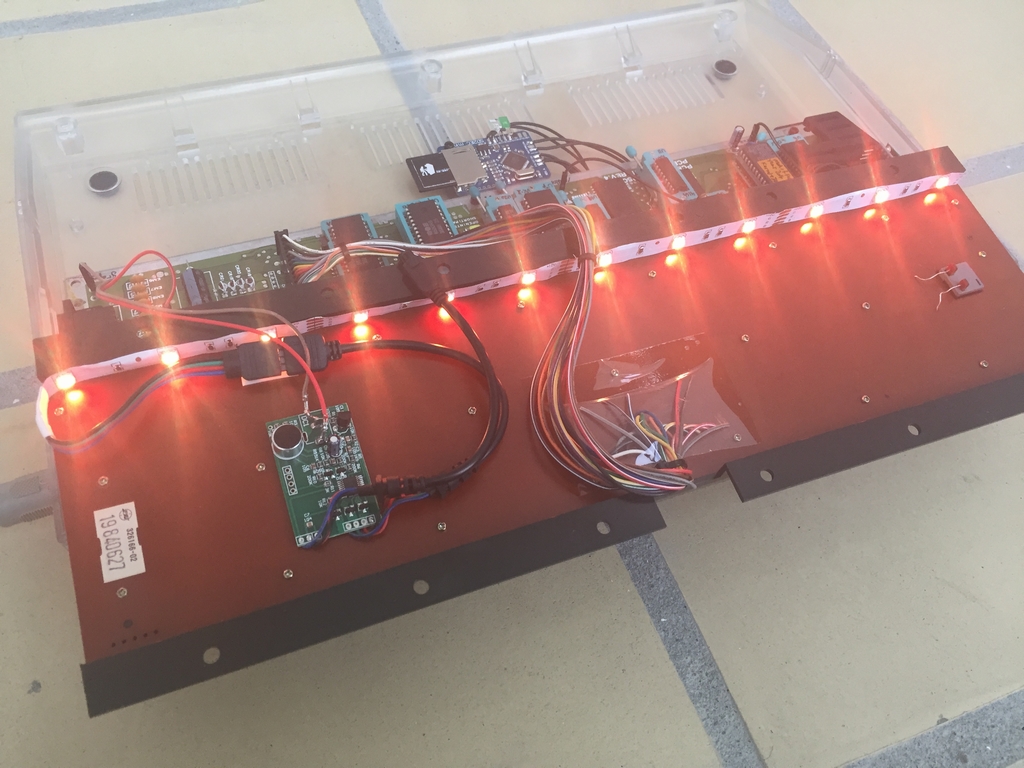
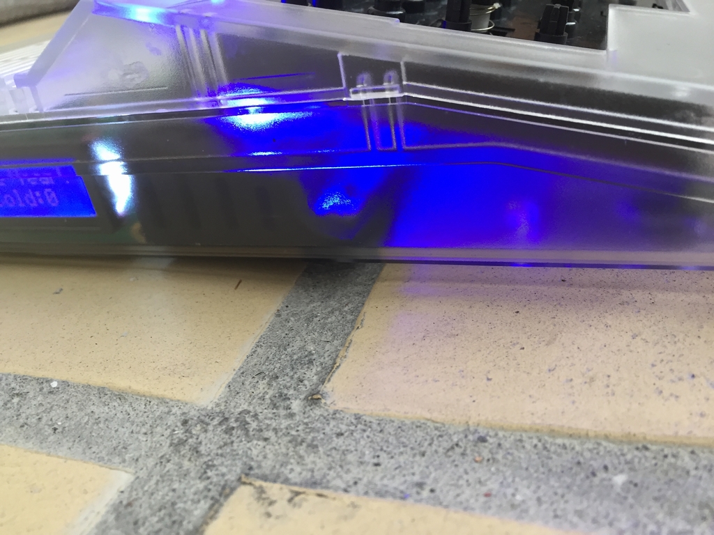
…and the LED colors can be seen through the case…
Here is a little video showing the Dashing Flashing C64 light mod in action.
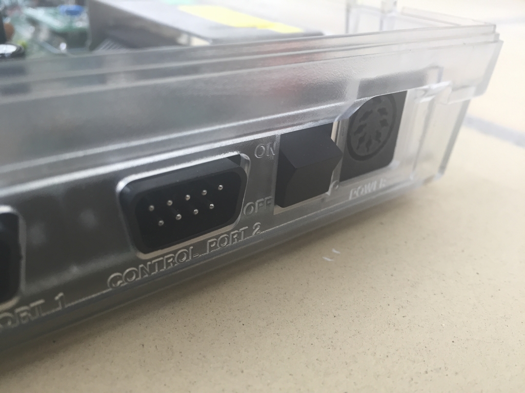
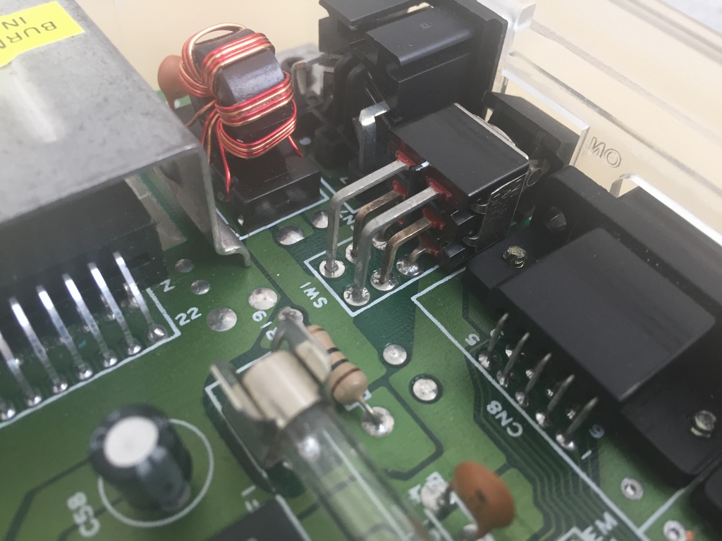
Power Switch Mod
The power switch was exchanged with a new one to keep the machine running for at least another 30 years! The old switches may go bad after a certain number of operations.
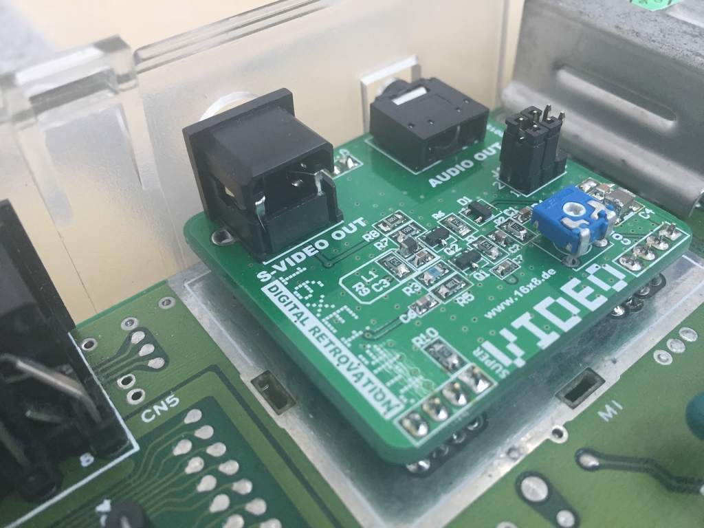
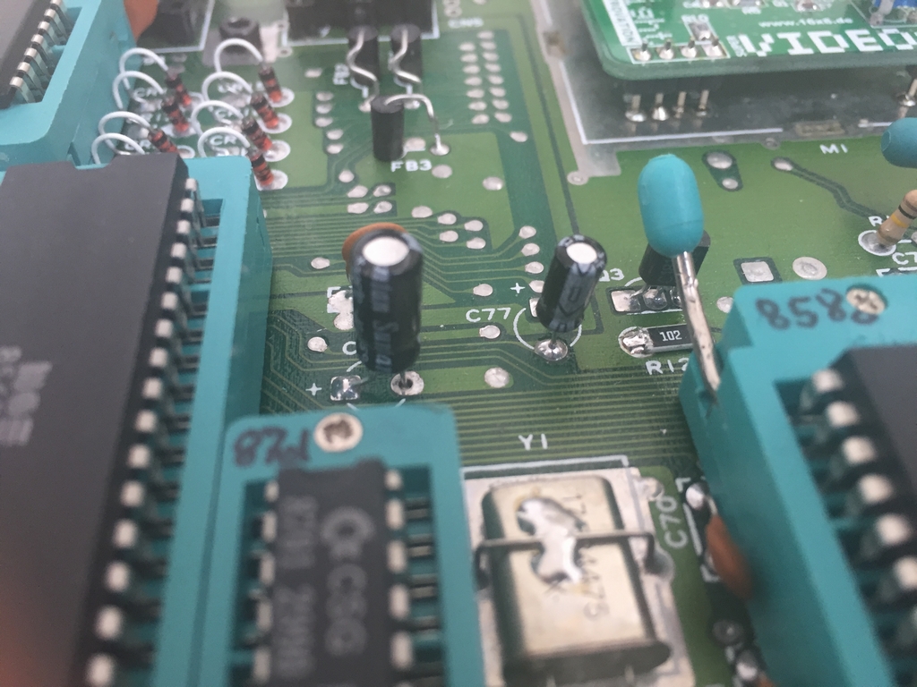
RF Modulator Mod
To optimize the video output of the machine, the RF modulator box was replaced with a new substitute circuit from 16×8 Digital Retrovation (link). The device is ‘plug-n-solder’ and is called a Super VIDEO board and has a S-video output connector and a 3.5 mm mini jack output plug for the sound. It only fits the Commodore 64 Version E short boards (Assy 250469, link), but should also fit the Commodore 128’s. The mod is described in further detail here (link).
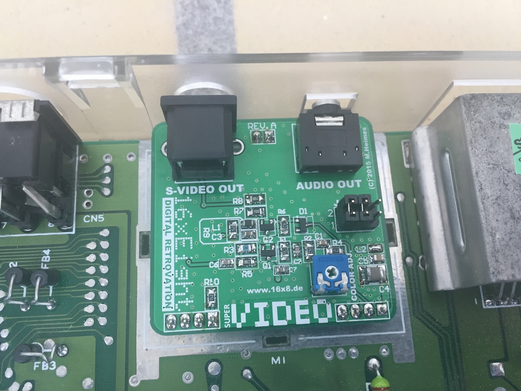
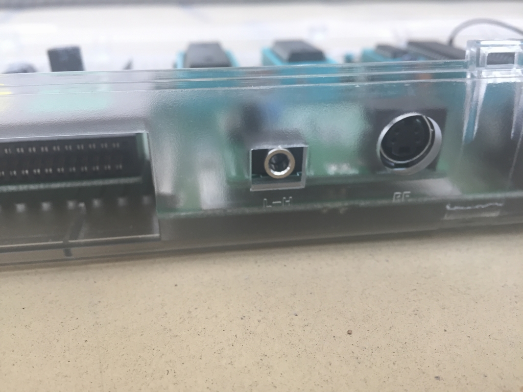
An easier approach would have been to use a LumaFix64 (link). However, as all major chips on this particular board had been replaced by ZIF sockets, there simply was no room for fitting a LumaFix64 into the machine.
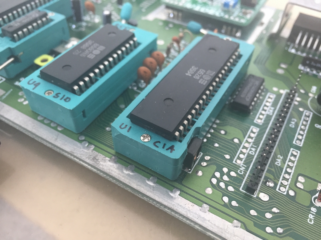
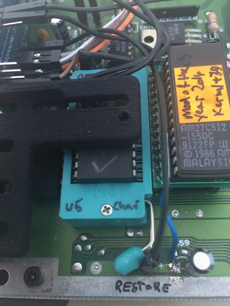
ZIF Socket Mod
In this mod, ZIF (Zero Insertion Force) sockets were installed for all the different chips to ease chip testing during repairs. The idea is that the risk of bending the pins when inserting and extracting chips would be reduced using these sockets. Only two chips had a leaf socket installed due to space issues on the board. If two identical chips were present (like the CIA and RAM chips), only one chip had a new socket installed. I used green ZIF sockets from 3M and TFXTOOL in size 7.62 mm and 15.24 mm depending on the size of the chips they should accomodate. The entire mod can be found here (link)
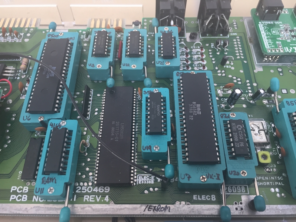
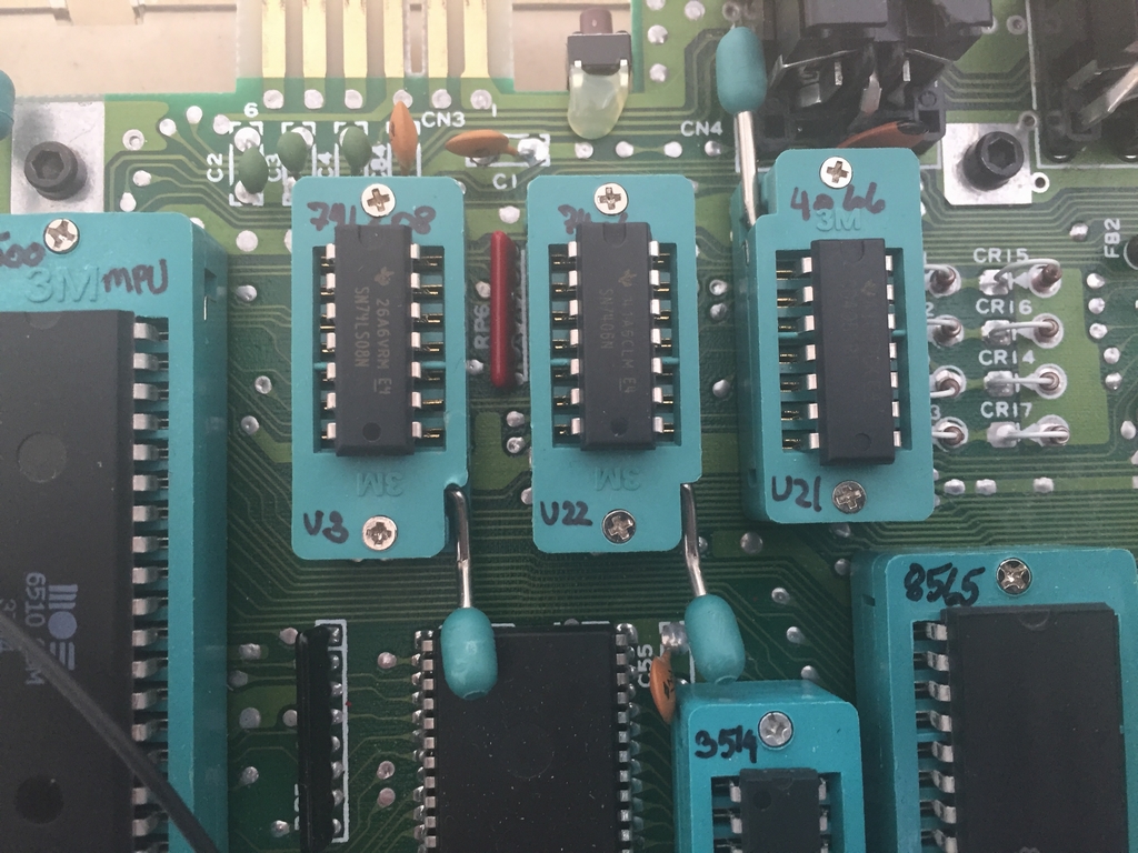
Space is an issue, but it should be possible to fit everything under the keyboard without too much trouble…
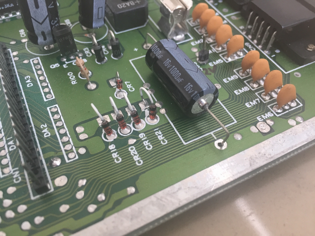
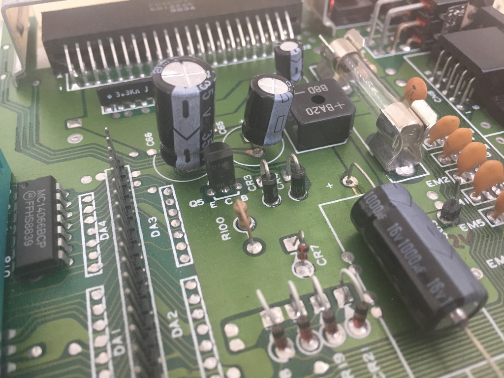
Capacitor Mod
All capacitors were also replaced as described here (link). This should make them work for another 30 years without drying out…
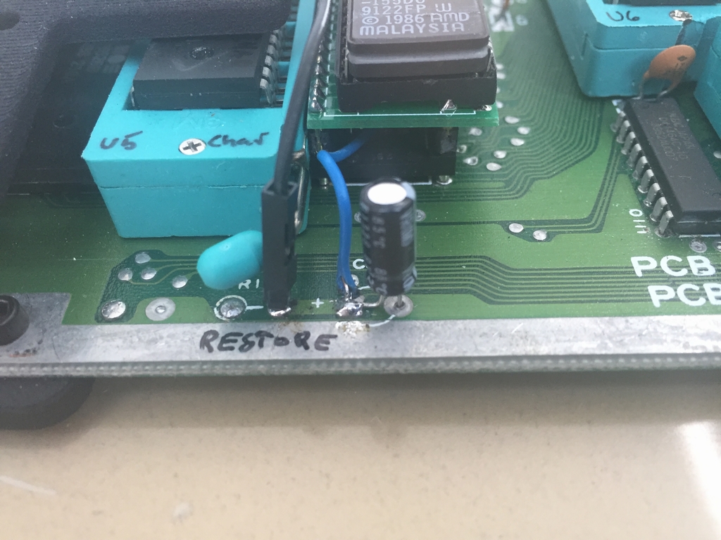
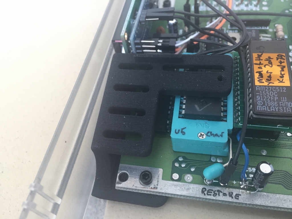
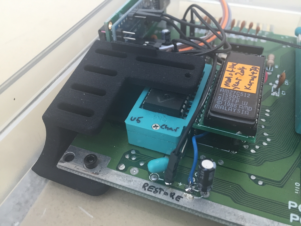
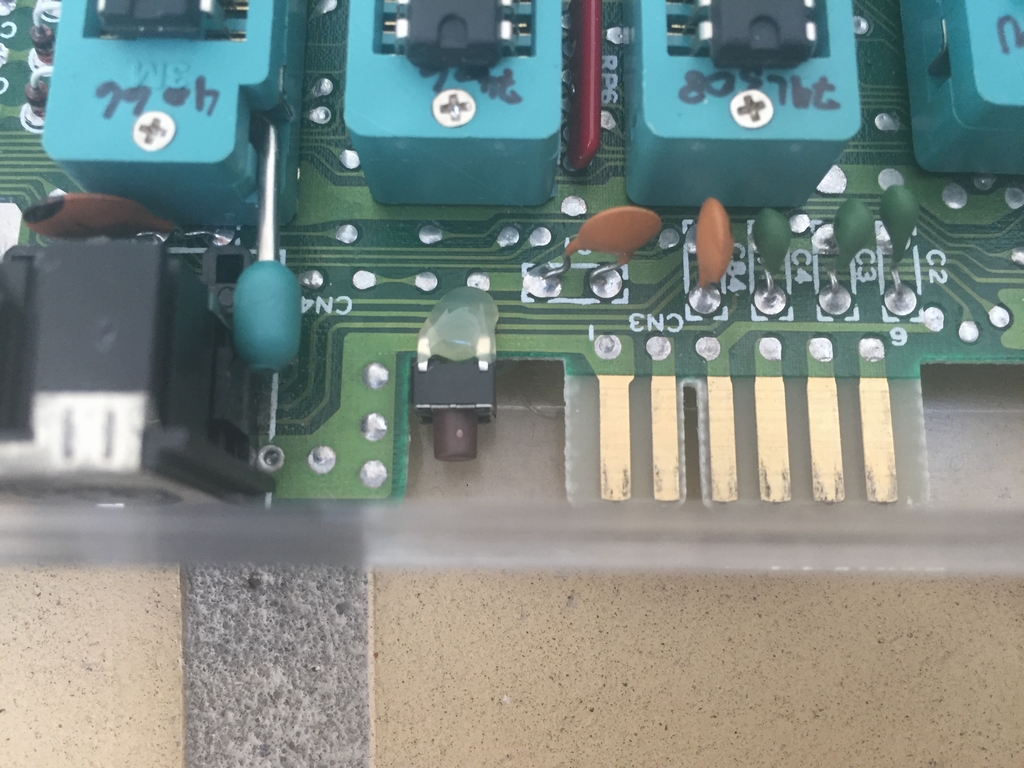
Switchless Kernal Mod
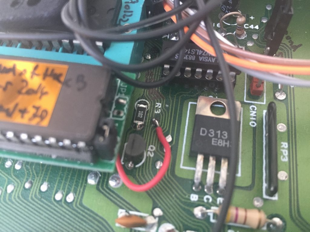
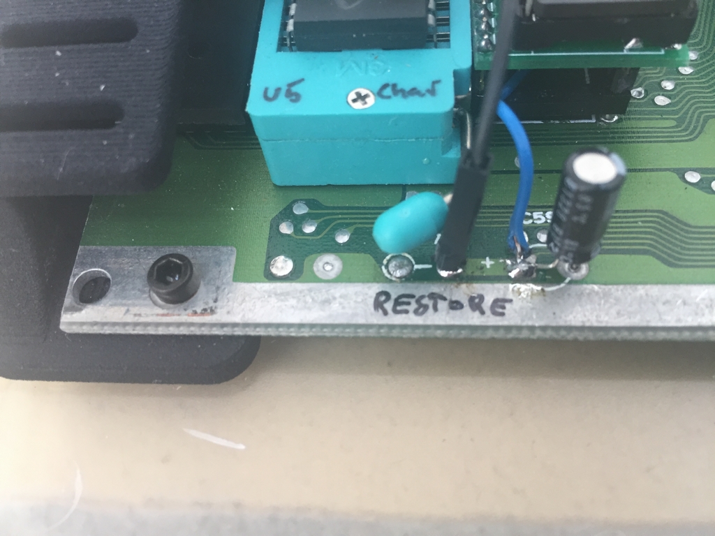
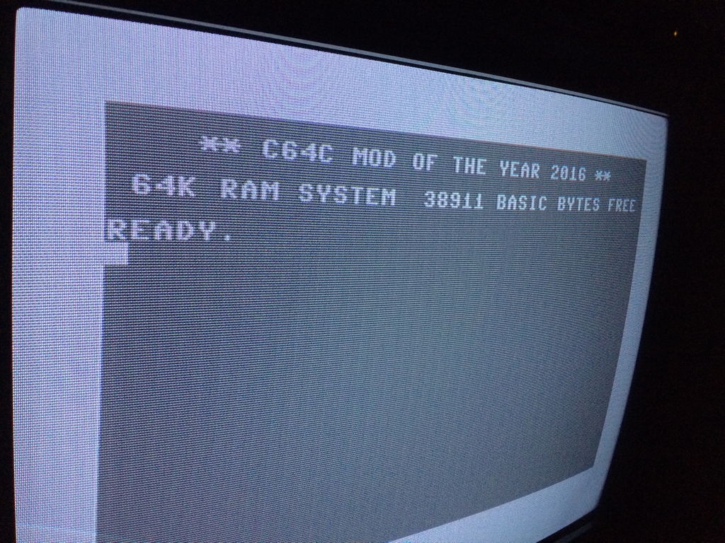
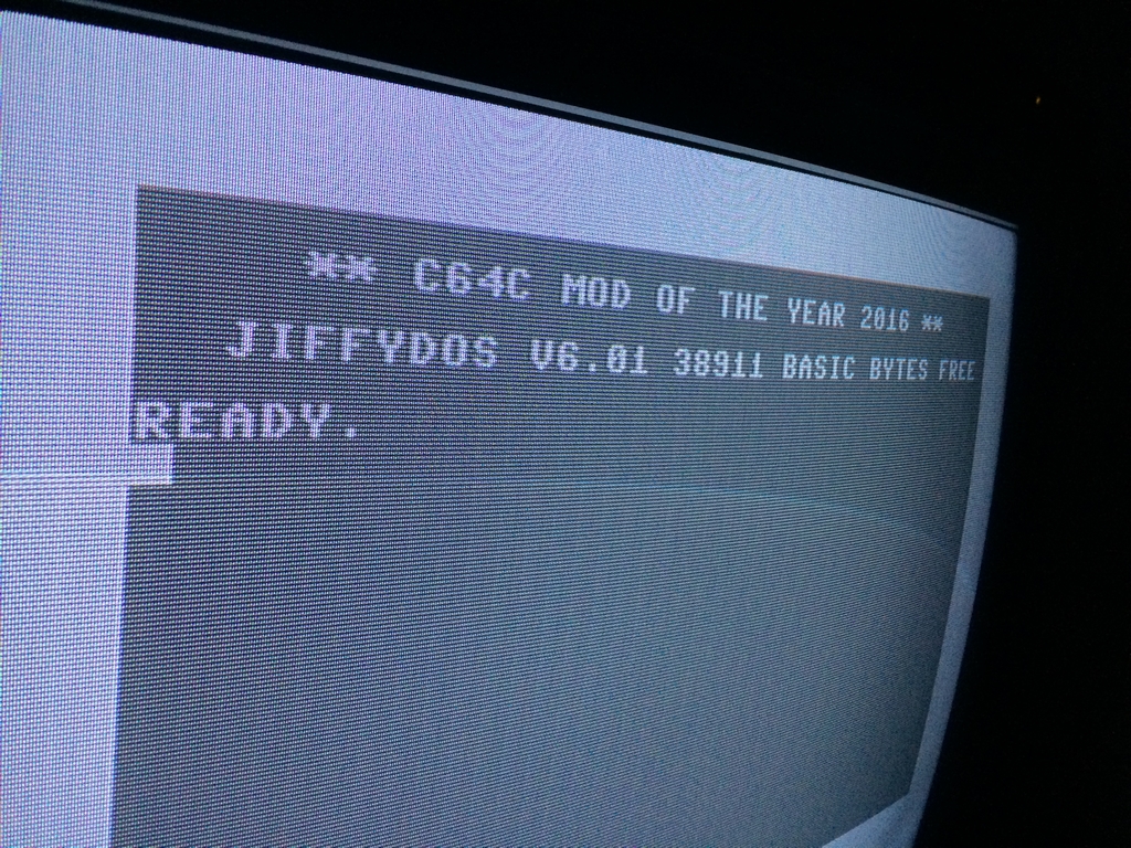
To swap between kernals (CBM Kernal & JiffyDOS), the original CBM Kernal IC has been replaced by a small PCB with both the original CBM Kernal and JiffyDOS. Pressing the RESTORE button during power up, the machine will boot into JiffyDOS. If nothing is pressed during power up, the machine boots into the standard CBM Kernal. I modified the Kernal to customize the colors and text of the BASIC screen. The changes were burned into a 27C512 EPROM. The entire mod and how to modify the C64 Kernals can be found here (link). The solder spots for the switchless Kernal unit can be found below.
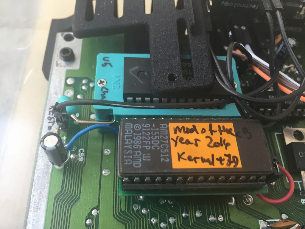
Custom Mod of the Year 2016 Kernal…
SD2IEC Mod
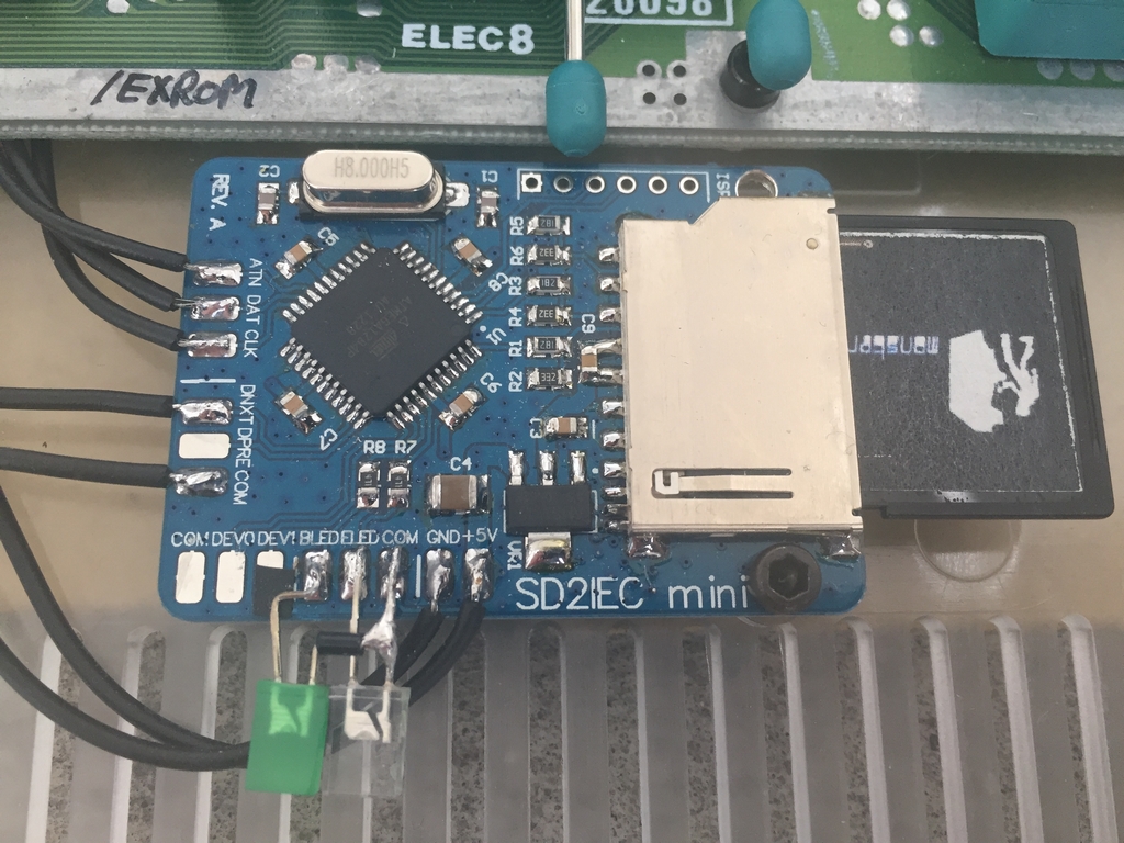
There are so many ways to load Commodore 64 games other than having to fiddle around with old 5.25″ floppies. One of these devices is the SD2IEC which have been described a few time already (link, link). The SD2IEC is a mass storage solution that uses a SD card for data storage (e.g. games and programs) and interfaces with the IEC bus of the Commodore 64. It does not emulate the 1541 diskette drive completely like the expensive 1541 Ultimate II does (link), but it reads quite a few .d64 and .prg files and it supports JiffyDOS natively (link)! For this mod I used the smallest device I could find – the SD2IEC Mini from 16×8 Digital Retrovation (link) (UPDATE: the device is now being sold by Heimes-elektronik.de). The entire mod can be found here (link).
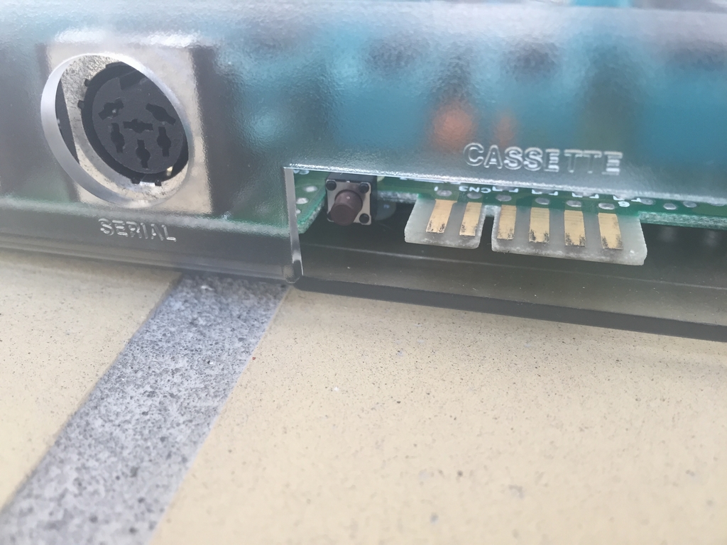
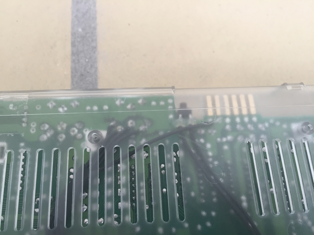
A ‘disk swap’ button was added/glued to the cassette port for changing disks during game play. Pressing it is easy using a finger and there is plenty of room for a Datasette to be inserted without issues.
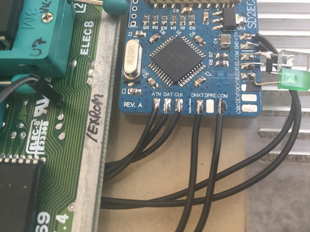
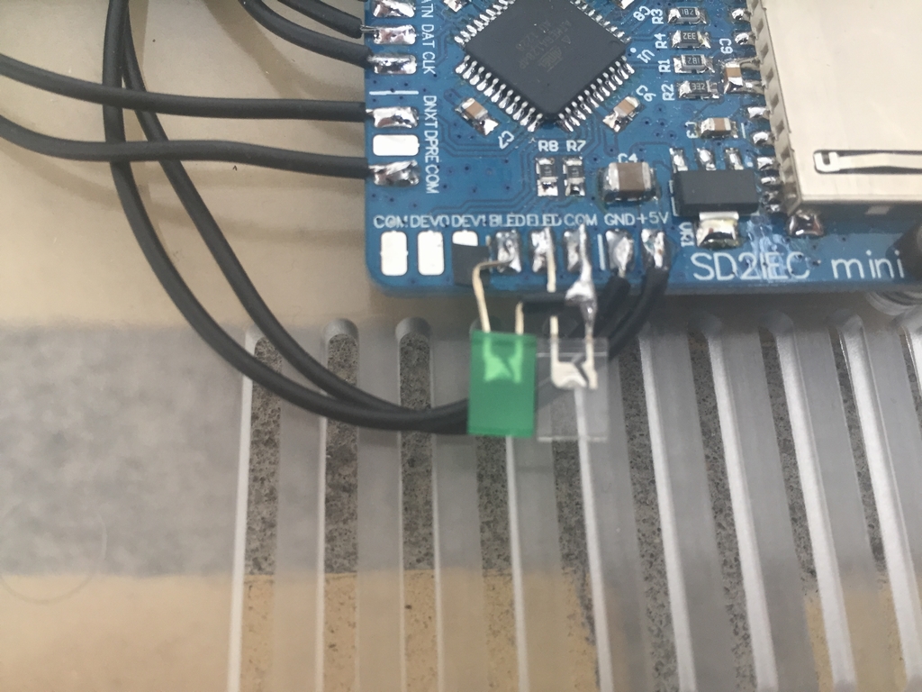
The device is attached to the center of the case. Access to the SD card for updating the content is not possible without taking the case apart. This was the best solution without having to drill holes into the case.
Switchless Reset Display Mod
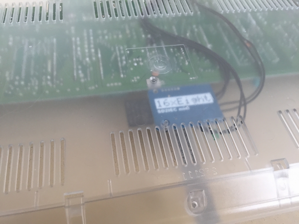
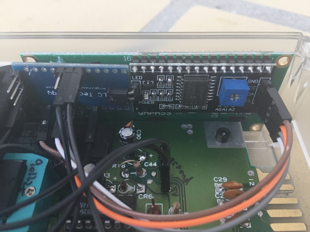
This is a mod of another mod called the Switchless Reset Mod (link), in which an Arduino Pro Mini is used to do Warm or Cold Resets (Soft and Hard Resets) depending on how long the RESTORE keys being pressed. Instead of just resetting the machine, I wanted to keep track of how many Warm and Cold Resets I had done since the last power-on and it should (of course) be shown on a nice blue LCD display. The entire mod can be found here (link).
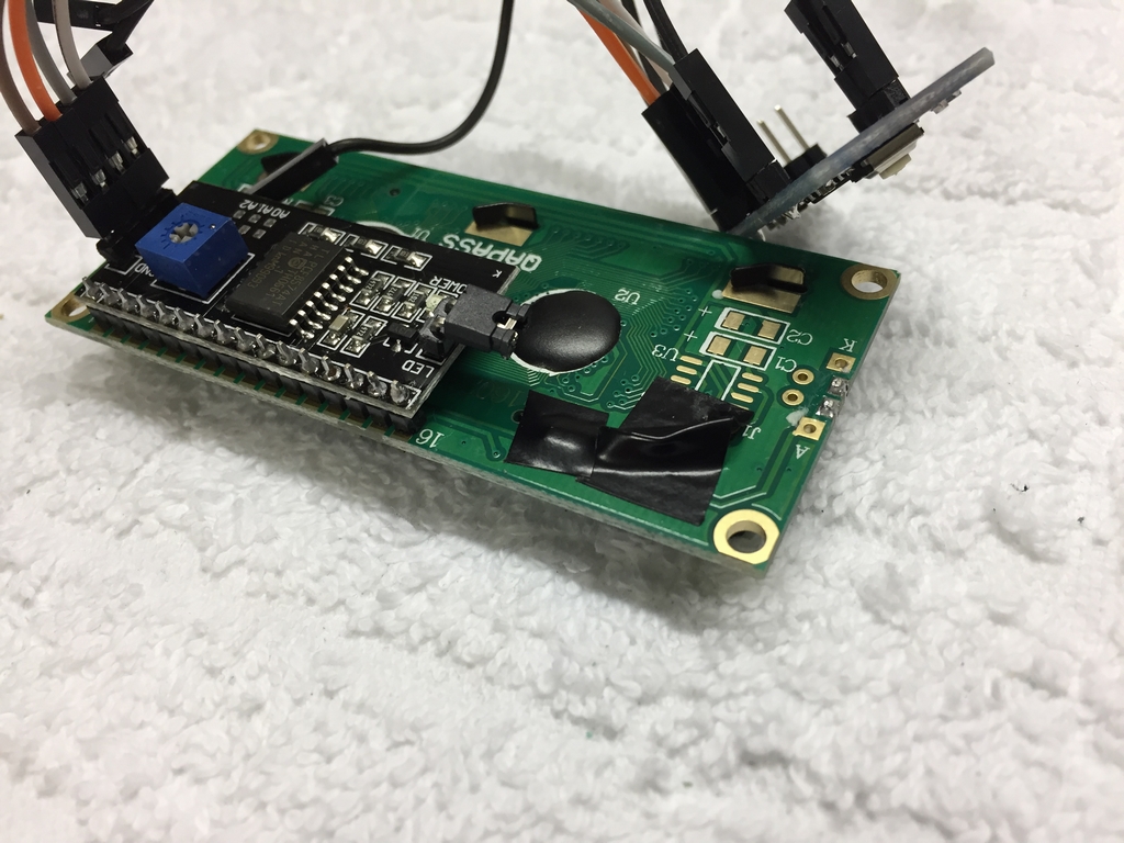
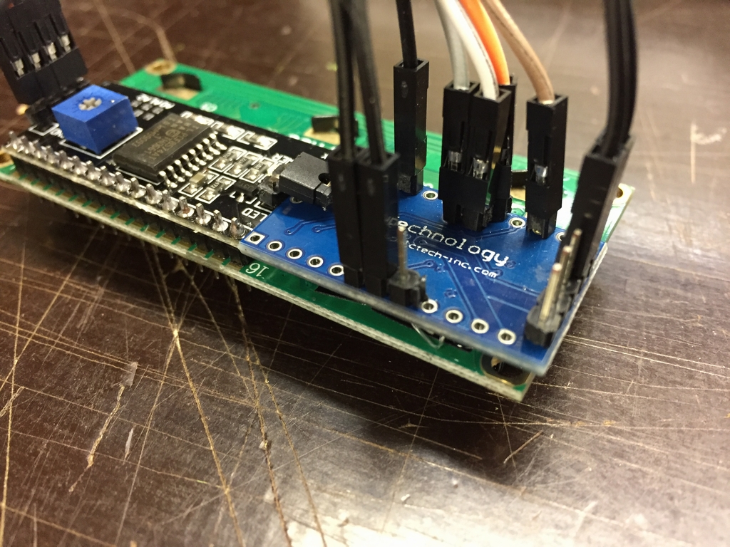
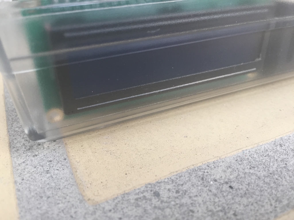
The back of the LCD was covered with some black tape to ensure that nothing would short circuit. The Arduino Pro Mini was then attached using a drop of hot glue. The display/Arduino was fitted between the motherbaord and the case side. This way the display text can read through the case side.
Holding the RESTORE button for 0.5-2 seconds (assuming that holds/hits shorter than 0.5 seconds are just normal key strokes) will tell the user to press longer! Holding RESTORE for 2-4 seconds will do a Warm Reset. Holding RESTORE for 4-8 seconds will do a Cold Reset. If the key is pressed for more than 8 seconds, nothing happens.
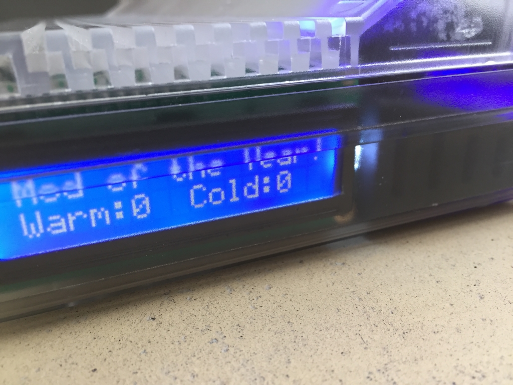
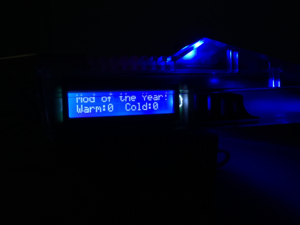
The display mod is locked and loaded…
A little video showing the mod in action.
Here is the source code for the Switchless Reset Display Mod. Double click to enable plain text view of the code. Changing the text written on the display should be pretty straight forward 🙂 Please use it at your own risk!
/*
  Version 1.01 (updated October 18th 2017)

  Purpose:
  Mod of the Year 2016 Display mod
  Switchless warm/cold reset system for a Commodore 64
  Show number of warm/cold resets on LCD display

  Warm reset:
  Clears any BASIC program stored in memory and resets the computer back to the opening blue screen

  Cold reset:
  If an extended pulse is applied to the /EXROM line at reset time, any machine language program will
  clear and resets the computer back to the opening blue screen.

  Function:
  If RESTORE button is pressed for < 0.5 seconds -> nothing happens
  If RESTORE button is pressed for 2-4 seconds -> RESET line LOW (Warm Reset)
  If RESTORE button is pressed for 4-8 seconds -> RESET line LOW & /EXROM line LOW for 300ms extra (Cold Reset)
  If RESTORE button is pressed for >8 seconds -> nothing happens

  Hardware:
  Arduino Pro Mini, ATmega328 (5V, 16MHz)
  16x2 I2C LCD display

  Disclamier:
  Tested on an Assy 250469 short board-> assumed to work across all motherboard versions
  Use at your own risk!

  Updates:
  Pinmode of the RESET and /EXROM lines are held as INPUT until requested to pull them LOW during Reset. This is to
  keep the Arduino from constantly driving the reset line and to support to support cartridges like the Final Cartridge III

  By MtnBuffalo/breadbox64.com 2017
*/

// Libraries
#include <Wire.h>                     // allows communication with I2C devices
#include <LiquidCrystal_I2C.h>        // controls liquid crystal displays (LCD)

// Constants
const int RESTORE_button = A0;        // pin A0 is connected to the RESTORE button (analog input pin)
const int RESET_line = 3;             // pin 3 is connected to the RESET line (digital output pin)
const int EXROM_line = 4;             // pin 4 is connected to the /EXROM line of the PLA (digital output pin)
const int press_time_warm = 2000;     // time in milliseconds before a warm reset is initiated
const int press_time_cold = 4000;     // time in milliseconds before a cold reset is initiated
const int voltageValue = 100;         // ADC value that will trigger the timer (voltages less than 0.5V) -> RESTORE pushed
const int warm_lcd = 0;               // for printing on the LCD
const int cold_lcd = 1;               // for printing on the LCD
const int too_short_press = 2;        // for printing on the LCD that the RESTORE press was too short
const int too_long_press = 3;         // for printing on the LCD that the RESTORE press was too long

// Variables
unsigned long RESTORE_press_time = 0; // the time the RESTORE button is being pressed in milliseconds
unsigned long StartTime = 0;          // first time stamp for calculating RESTORE_press_time
int firstpress = 1;                   // test if the RESTORE button has been pressed
int analogValue;                      // ADC value (0-1023) read from the RESTORE button
int coldResets = 0;                   // total number of Cold Resets since the computer was turned on
int warmResets = 0;                   // total number of Warm Resets since the computer was turned on

// Functions
int debounce();                       // debounce function to get ADC value (analogValue)
void lcd_print(int);                  // print function for the LCD display

// Objects
// connect SDA line from the LCD to A4 on the Ardunio (analog input pin)
// connect SCL line from the LCD to A5 on the Ardunio (analog input pin)
LiquidCrystal_I2C lcd(0x3F, 2, 1, 0, 4, 5, 6, 7, 3, POSITIVE); // set LCD I2C address (some LCD's use 0x27)

void setup()
{
// initialize digital pins
  pinMode(RESET_line, INPUT);         // digital pin 3 on the Arduino Pro Mini - Set as OUTPUT before reset
  pinMode(EXROM_line, INPUT);        // digital pin 4 on the Arduino Pro Mini - set as OUTPUT before reset

  digitalWrite(RESET_line, HIGH);     // initial RESET_line state
  digitalWrite(EXROM_line, HIGH);     // initial EXROM_line state

  pinMode(RESTORE_button, INPUT);     // analog pin A0 on the Arduino Pro Mini
  analogReference(DEFAULT);           // setting the analog reference to 5V

  // initialize LCD with start-up text
  lcd.begin(16, 2);                   // set up the LCD's number of rows and columns & turn on backlight
  lcd.setCursor(0, 0);                // set cursor to first character (column=0) on the top line (line=0)
  lcd.print("Mod of the Year!");      // print standard text on the LCD
  lcd.setCursor(0, 1);                // set cursor to first character (column=0) on the bottom line (line=1)
  lcd.print("Warm:   Cold:");         // print standard text to bottom line of LCD
  lcd.setCursor(5, 1);                // set cursor to 6th character (column=5) on the bottom line (line=1)
  lcd.print(warmResets);              // print value
  lcd.setCursor(13, 1);               // set cursor to the 14th character (column=13) on the bottom line (line=1)
  lcd.print(coldResets);              // print value
}

void loop()
{
  analogValue = debounce();                       // call debounce function to get average ADC value
  if(analogValue < voltageValue)                  // checks if the RESTORE button has been pressed
  {
        // initiate RESTORE push timer
        if(firstpress == 1)
        {
          firstpress = 0;
          StartTime = millis();                   // first time stamp
          delay(2);                               // make sure that RESTORE_press_time will become > 0 milliseconds
        }
     RESTORE_press_time = millis() - StartTime;   // variable holds total time RESTORE is pressed
   }
   else if(firstpress == 0) firstpress = 1;       // RESTORE button has been released

  // Warm reset (cancel reset if RESTORE is pushed < press_time_warm -> 2 seconds)
  if (firstpress == 1 && RESTORE_press_time > press_time_warm && RESTORE_press_time < press_time_cold)
  {
    pinMode(RESET_line, OUTPUT);                  // set as output to pull down the reset line
    digitalWrite(RESET_line, LOW);                // anode side of CR5 diode (Assy 250469) LOW
    delay(200);
    digitalWrite(RESET_line, HIGH);               // reset RESET_line
    RESTORE_press_time = 0;                       // reset timer
    pinMode(RESET_line, INPUT);                   // reset the RESET line
    warmResets++;                                 // update counter for the LCD display
    lcd_print(warm_lcd);                          // call print function for updating number of resets
  }

  // Cold reset (cancel reset if RESTORE is pushed > 8 seconds)
  else if (firstpress == 1 && RESTORE_press_time > press_time_cold && RESTORE_press_time < 8000)
  {
    pinMode(RESET_line, OUTPUT);                  // set as output to pull down the reset line
    pinMode(EXROM_line, OUTPUT);                  // set as OUTPUT to pull down the /EXROM line
    digitalWrite(RESET_line, LOW);                // anode side of CR5 diode (Assy 250469)LOW
    digitalWrite(EXROM_line, LOW);                // /EXROM line of the PLA LOW
    delay(200);
    digitalWrite(RESET_line, HIGH);               // reset RESET_line
    delay(300);
    digitalWrite(EXROM_line, HIGH);               // reset EXROM_line

    RESTORE_press_time = 0;                       // reset timer
    pinMode(RESET_line, INPUT);                   // reset the RESET line
    pinMode(EXROM_line, INPUT);                   // reset the /EXROM line

    coldResets++;                                 // update counter for the LCD display
    lcd_print(cold_lcd);                          // call print function for updating number of reset
  }

  // print to LCD that the RESTORE press was too short but longer than a key stroke (0.5-2 seconds push)
  else if (firstpress == 1 && RESTORE_press_time > 500 && RESTORE_press_time < press_time_warm)
  {
    RESTORE_press_time = 0;                       // reset timer
    lcd_print(too_short_press);
  }
  // print to LCD that the RESTORE was pressed for too long > 8 seconds
  else if (firstpress == 1 && RESTORE_press_time > 8000)
  {
    RESTORE_press_time = 0;                       // reset timer
    lcd_print(too_long_press);
  }
}

// Debounce function to filter transistions/noise of the analog reading
int debounce()
{
  int x, meanADC, sum = 0;
  for (int i = 0; i < 5; i++){                          // reads ADC value from pin A0 5 times
     delay(5);                                          // debounce for 25 ms total
     sum += analogRead(RESTORE_button);
  }
  x = sum / 5;                                          // mean ADC value
 (x < voltageValue) ? (meanADC = x) : (meanADC = 1023); // if/else check - has RESTORE been pushed?
  return meanADC;                                       // return mean ADC value to main loop
}

// print function for updating the number of resets
void lcd_print(int y)
{
  lcd.clear();                       // clear LCD and sets cursor to first character on display
  switch (y)
  {
    case warm_lcd:
      lcd.print(" Warm Reset...  ");
      break;
    case cold_lcd:
      lcd.print(" Cold Reset...  ");
      break;
    case too_short_press:
      lcd.print(" Press longer!!!");
      break;
    case too_long_press:
      lcd.print("Let go faster!!!");
      break;
  }
  delay (3000);
  lcd.clear();                      // clear LCD and sets cursor to first character on display
  lcd.print("Mod of the Year!");    // re-print standard text on the LCD
  lcd.setCursor(0, 1);              // set cursor to first character (column=0) on the bottom line (line=1)
  lcd.print("Warm:   Cold:");       // re-print standard text to bottom line of LCD
  lcd.setCursor(5, 1);              // set cursor to 6th character (column=5) on the bottom line (line=1)
  lcd.print(warmResets);            // print value
  lcd.setCursor(13, 1);             // set cursor to the 14th character (column=13) on the bottom line (line=1)
  lcd.print(coldResets);            // print value
  return;
}
New Keycaps
Hopefully Phase5 will speed things up so that the Mod of the Year 2016 and Mod of the Year 2015 can be updated with some nice new keycaps… Fingers crossed!
© breadbox64.com 2016